1
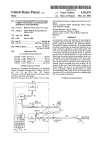
US00540488SA
United States Patent [191
[11]
[45]
Sheehan et a1.
[54] FILTER UNIT FOR END-TIDAL CARBON
[75] Inventors: Neil J. Sheehan, Palo Alto; Scott R.
Rouw, Union City; Robert T. Stone,
Sunnyvale, all of Calif.
Natus Medical, Incorporated, San
Carlos, Calif.
‘ Product Literature-KNF Diaphragm Micro Pump
Type NMP 02 (2 pages).
Primary Examiner-—Lee S. Cohen
Assistant Examiner-Robert L. Nasser, Jr.
Attorney, Agent, or Firm—Davis, Hoxie, Faithfull &
ABSTRACT
A noninvasive device and methods for measuring the
end-tidal carbon monoxide concentration in a patient’s
breath, particularly newborn and premature infants.
Division of Ser. No. 990,425, Dec. 15, 1992, aban
The patient’s breath is monitored. An average carbon
doned, which is a continuation-in-part of Ser. No.
monoxide concentration is determined based on an av
899,261, Jun. 16, 1992, Pat. No. 5,293,875.
[51]
red Transducer brochure (2 pages) and technical note (9
[57]
Jan. 21, 1994
Related US. Application Data
[60]
Apr. 11, 1995
Hapgood
[21] Appl. No.: 184,379
[22] Filed:
5,404,885
pages).
MONOXIDE MONITOR
[73] Assignee:
Patent Number:
Date of Patent:
erage of discrete samples in a given time period. The
Int. 01.6 .............................................. .. A61B 5/08
[52] US. Cl. .................................. ..128/716;128/719;
128/204.22; 422/83; 73/233
[58]
Field of Search ................. .. 128/716, 719, 204.22,
[56]
128/204.23, 205.22; 422/83, 84; 73/233
References Cited
U.S. PATENT DOCUMENTS
3,977,394
8/1976 Jones et al. ...................... .. 128/2.07
4,304,578 12/1981 Hakala et a1.
128/719
4,423,739 l/l984
128/719
4,821,737
4/1989
..
4,831,024 5/ 1989
4,870,961 10/1989
4,886,528 11/1989
4,968,887
5,003,985 ll/
4/1991
1990 White et al. .................. .. 364/4l3.03
OTHER PUBLICATIONS
ratio of the end-tidal portion of the breath ?ow sample '
is separately determined, preferably based on monitor
ing the level of carbon dioxide in the gas sample and
identifying the carbon dioxide concentration levels cor
responding to the end-tidal portion of the breath sam
ple. The sensed carbon monoxide level is converted to
the end-tidal carbon monoxide level by subtracting the
ambient carbon monoxide level and dividing the re
mainder by the ratio of end-tidal breath to breath in the
breath sample. An easy to use microcontroller-based
device containing a carbon dioxide detector, a carbon
monoxide detect and a pump for use in a hospital, home,
physician’s of?ce or clinic by persons not requiring high
skill and training is described. A replaceable ?lter unit
made of a single tri-lumen PVC extrusion and a tube
segment inter-connecting two of the lumens used to
provide the consumable ?ltration material. The ?ltra
tion material is interposed between the carbon dioxide
sensor and the carbon monoxide sensor which are
Yeung et 211., “Automatic End Expiratory Air Sampling
Device For Breath Hydrogen Test In Infan ”, The
Lancet, vol. 337, pp. 90-93 (Jan. 12, 1991).
Product Literature—Z World Engineering Little Giant
Miniature Microcontroller (One page).
mounted inside the monitor housing. The ?lter unit also
interfaces the canula for receiving the patient’s breath
sample and a hydrophobic ?lter between the patient and
the carbon dioxide monitor.
Product Literature-Servomex Mode 1505 C02 Infra
16 Claims, 11 Drawing Sheets
002
nonnoa
@?igllalgiill —
~~ -- --
- -
I. 5- I... -‘II‘JF'.’ I.
US. Patent
Apr. 11, 1995
Sheet 1 of 11
M@5E2:3
%E5mm5E5
\no?‘
21
2
5,404,885
US. Patent
Apr. 11, 1995
Sheet 3 of 11
5,404,885
W2
:2
.28.
AI_
E5:50E2
‘N@2\:|x2"3\
2-\. 1v
:2:2 :
I J:EI23
/(o:52555ageN3s:.
.‘ 252:
S
E
5
6
a
:
t
5
:
2
8
5
1
:
?
‘52\:.57s.2Z%2:I2 %;: :2.5$025:.2 2E5:
:22EE:N28.2o52n?.5
_.E2Q5_3z§2.%_é
~
~_3.2;:
a:E5E:2 .“%;E.
E$2:252%m2:8z35%E23.
0A.‘ ‘
5 2E:2%2:<251:2:.
2.523g8%30: E2.23Z:52E;O.
y‘5.21.2:
loM__5,3E:25 s2:5
2E.:532 ;?
125:3 .:2.5522a5g2e%:
US. Patent
E@9593
r...r50
A
E2g53.%»
Apr. 11, 1995
82o:
Sheet 8 0f 11
5,404,885
US. Patent
Apr. 11, 1995
Sheet 9 0f 11
5,404,885
1.25
0.50
V00
_
000i
025
*2
FIG. 34
"ME--
0
L25.
0.50
0.00
NWWUMM/UUUUUUUUU
‘0'
TlME-—-—~
_
F/ 6. 3B
002 0000000010100 0R
0 EQUIVALENT 002 SENSOR RESPONSE
002 = $02 MEAN
DC ‘ DUTY CYCLE
w ?k_ _/£1U(:\__
(20
,
-
Flat 45
B
U.S. Patent
Apr. 11, 1995
Sheet 10 of 11
5,404,885
US. Patent
‘hE
5E
Apr. 11, 1995
Sheet 11 of 11
5,404,885
?’
H. u . .
. r. “H. .H .“ H". .i.:f
...
.1..
a
\
¢
I 1
\
New
1
5,404,885
FILTER UNIT FOR END-TIDAL CARBON
MONOXIDE MONITOR
2
ment to analyze the acquired sample. In addition, this
technique requires time and personnel to transport the
sample from the patient to the laboratory (or equip
ment) where the analysis is conducted, and then to
CROSS REFERENCE TO RELATED
5 report back to the attending physician/practitioner for a
APPLICATIONS
diagnosis and prescription, if any.
Another problem with this technique is that accurate
This is a divisional of U.S. Pat. application No.
assessment of the concentration difference in carbon
07/990,425, ?led Dec. 15, 1992, now abandoned, which
is a continuation-in-part of U.S. Pat. application
07/899,26l, ?led Jun. 16, 1992, now U.S. Pat. No.
monoxide requires obtaining good samples of end-tidal
patient breath. This essentially requires that the patient
5,293,875.
have a regular, predictable breathing cycle. Thus, it can
be dif?cult to obtain a good sample by watching chest
FIELD OF THE INVENTION
wall movement, particularly for a newborn and for
This invention relates to methods and apparatus for
patients having irregular breathing cycles.
invivo, real time measurement of end-tidal carbon mon 15
Chemical electrochemical sensors capable of measur
oxide concentration in the exhaled breath, more partic
ing carbon monoxide concentrations in the range of
ularly to a ?lter unit for use in the determination of
interest, 0 to 500 parts per million (ppm), are commer
end-tidal carbon monoxide concentration in the breath
cially available, e.g., model DragerSensor CO available
of a newborn infant.
BACKGROUND OF THE INVENTION
In most animal systems, carbon monoxide is a waste
from Dragerwerk, Lubeck, Germany. However, such
sensors are sensitive to many other gases as well as
carbon monoxide, and are therefore susceptible to er
ror. Another problem with such sensors is that the mea
product produced in the breakdown of free hemoglobin
surement dynamics of the sample gas transport through
within the blood. Ordinarily, hemoglobin is contained
the gas permeable membrane and oxidation-reduction in
within red blood cells and is stable. However, aging of 25 the electrochemical cell results in a relatively slow
red blood cells and certain disease processes produce
response time such that discrete samples of the end-tidal
hemolysis, i.e., the breakdown of the cell wall. This
breath must be obtained and analyzed to determine the
produces free hemoglobin which breaks down in the
end-tidal carbon monoxide concentration.
blood. The carbon monoxide that is produced by the
breakdown of free hemoglobin is normally excreted in 30
SUMMARY OF THE INVENTION
the breath.
When the system is in equilibrium, the carbon monox
ide concentration in the breath is proportional to the
difference in the concentration of carbon monoxide in
It is, therefore, an object of the present invention to
provide improved non-invasive apparatus and methods
for measuring carbon monoxide concentration in the
the blood and the concentration of carbon monoxide in 35 end-tidal breath. It is another object to provide appara
tus and methods that operate in real-time. It is another
room air. This difference in concentration is propor
object
to provide apparatus and methods for use in
tional to the rate of hemolysis in the blood.
determining the rate of hemolysis from the concentra
The concentration of carbon monoxide in the end
tion of end-tidal carbon monoxide.
tidal breath, i.e., the gas that is last expelled each breath,
It is another object of the present invention to pro
is presumed to be at equilibrium with the concentration
vide apparatus and methods for measuring end-tidal
in the blood. This is because the end-tidal breath con
carbon monoxide that do not require a highly skilled,
tains predominantly, if not exclusively, the gas expelled
trained individual to obtain and determine the measure.
from the alveoli in the lungs, which gas was within the
It is another object to provide such apparatus and meth
alveoli for a time generally suf?cient to equilibrate with
ods that do not require incrementally acquiring samples
the blood.
It is known that hemolysis and the resulting by
of end-tidal breath during successive respiratory cycles.
products and consequences of hemolysis can be esti
It is another object of the invention to provide a
portable, easy-to-use apparatus that can be used in a
nursery, a physician’s of?ce, a hospital, a clinic, and a
mated or predicted from a measure of the concentration
of carbon monoxide in the end-tidal breath. See Smith,
D. W. et al., “Neonatal Bilirubin Production Estimated 50 mobile clinic for measuring end-tidal carbon monoxide
in real-time, for assessing the likelihood of elevated
from End-Tidal Carbon Monoxide Concentration”,
levels of hemolysis for immediate entry on the patient’s
Journal of Pediatric Gastroenterology and Nutrition,
record and prescription of an appropriate remedy.
3:77-80, 1984.
It is another object of this invention to provide an
One method of analysis previously reported includes
incrementally acquiring a sample of end-tidal breath 55 end-tidal carbon monoxide monitor with a replaceable
?lter unit for use with different patients, and for replac
and analyzing the acquired sample by mass spectros
copy or gas chromatography to determine the end-tidal
ing consumed gas ?ltering components. It is another
carbon monoxide concentration. The sample is obtained
object to provide an inexpensive disposable ?lter unit.
by extracting from each of several successive breaths a
It is another object of this invention to provide keyed
portion of the apparent end-tidal breath using a syringe.
bulkhead ?ttings on the monitor for receiving the ?lter
The end-tidal portion of breath is determined by observ
in the correct orientation and to provide for proper
ing the chest movements of the infant. See, e.g., Vreman
?ow path interconnection and operation of the dispos
able ?lter in the monitor.
et a1. U.S. Pat. No. 4,831,024.
One problem with this technique is that it requires a
In accordance with this invention, there is provided
skilled, trained user to obtain the end-tidal sample in 65 an apparatus, sampling methods, and analysis tech
successive increments based on watching chest wall
niques for measuring the concentration of end-tidal
movements. It also requires a trained, skilled person to
carbon monoxide in breath, particularly in newborn and
operate a complex piece of analytical laboratory equip
premature infants. Broadly, the invention concerns de
3
5,404,885
termining the concentration of end-tidal carbon monox
4
sampled at the patient into the monitor, more speci?
cally, from the nasal canula to the carbon dioxide detec
tor. The second ?ow path contains the consumable
?ltration medium and provides a ?ow path between the
ide based on a measure of the room air carbon monoxide
concentration, a measure of the average carbon monox
ide concentration for a breath sample over a period of
time, and a determined ratio of the end-tidal breath to 5 carbon dioxide sensor and the carbon monoxide sensor.
inspired air for the sampled portion.
In a preferred embodiment, the assembly is formed of
a body having three flow paths (also called lumens)
The present invention is based in part on the discov
ery that accurate assessment of end-tidal carbon monox
ide concentration may be obtained based on knowledge
extending from one end to the other and a tube segment
that is used to connect two of the ?ow paths at one end
of the fraction of the gas sample that is end-tidal gas. 0 of the body. The consumable filtration medium is lo
Thus, the present invention is able to avoid selectively
sampling small samples of end-tidal breath over succes
cated in one of the two lumens connected by the tube
sive respiratory cycles to obtain a suf?ciently large
end-tidal breath sample, which incremental sampling is
path from the carbon dioxide detector, through the
segment. Thus, the tube segment provides for a gas ?ow
consumable ?ltration medium, and to the carbon mon
problematic. Further, the invention advantageously
oxide detector. Preferably, the three lumens are straight
uses a conventional carbon monoxide detector, which
and have longitudinal axes that are in the same plane.
has a response time that is not fast enough to distinguish
carbon monoxide in end-tidal breath from carbon mon
oxide in inspired air, to derive the end-tidal carbon
monoxide concentration in real-time. More particularly,
More preferably, the three lumens have different inte
rior dimensions and respectively mate to corresponding
differently sized bulkhead ?ttings on the monitor. This
ensures that the ?lter unit will be installed in the correct
a conventional carbon monoxide detector can be used
to obtain the average carbon monoxide concentration
orientation with tight interconnections.
In the preferred embodiment, the body and its lumens
are formed by coextrusion of a single piece of plastic
material, e.g., soft polyvinyl chloride. The consumable
level during breathing, which average value can be
related to the end-tidal value based on the determined
ratio of end-tidal to inspired breath. Preferably, the 25 ?ltration medium is then inserted in one of the lumens of
the second flow path. A plug is inserted into the distal
most common interfering substances from a sampled
breath are removed from the sample by a consumable
?ltration medium so that these substances do not affect
the measurement. The present invention also applies to
gas components of exhaled breath other than carbon
end of that lumen, which has a ?ow passageway extend
ing through the plug for receiving a length of the tube
segment.
The piece of tubing is bent into a U-shape to intercon
nect the two selected lumens. In this regard, the tube
segment preferably has an outer diameter that provides
monoxide, which gas components cannot be directly
monitored because of the slow response time of avail
able gas detectors.
an air tight frictional ?t- when it is inserted in the plug
One aspect of the present invention concerns using a
second gas component of the breath, other than the ?rst
flow passageway and the other lumen of the second
gas component whose concentration is being moni
its length to minimize the likelihood of the tube collaps
ing or pinching closed when it inserted in the paths. The
tube segment is preferably secured to each of the plug
?ow passageway and the other lumen, which are of
?ow path. Preferably, the tubing has interior ribs along
tored, to determine the ratio of the end-tidal breath to
inspired air. The relative concentration level of the
second gas during respiration is monitored and the ratio
or duty cycle of the end-tidal portion of the sensed 40 about the same inner dimension (diameter), by a con
concentration waveform relative to the inspired air is
ventional solvent dipping and bonding process.
determined. A sensor for detecting the level (or concen
Another aspect of the invention is directed to provid
tration) of the second gas having a time response that is
ing a hydrophobic ?lter that plugs into the distal end of
fast enough to distinguish the end-tidal breath concen
the lumen of the ?lter unit forming the ?rst ?ow path.
tration from the inspired air is preferably used. One 45 A conventional ?tting for receiving the hydrophobic
suitable gas component is carbon dioxide, which has a
?lter is interposed between the canula tubing that is
large, distinctive change in concentration with breath
used to take the breath sample from the patient and the
ing. Other gases may be used, e.g., hydrogen, oxygen,
?lter unit. This construction is particularly advanta
or some combination of gases, e.g., carbon dioxide and
geous because the ?lter and ?tting elements are quickly
hydrogen.
and easily assembled by the end user, and alternately
The determined end-tidal carbon monoxide concen
tration may be used by a physician or other suitable
health care provider to evaluate the rate or relative
level of hemolysis occurring in the infant. The evalua
tion is typically made by comparing the determined
can be provided in a preassembled con?guration in a
clean, but not necessarily sterile package. In addition, it
also is extremely low cost because it uses a combination
of conventional commercial parts.
The present invention provides a tool for predicting
end-tidal carbon monoxide concentration to known or
the likelihood that the determined level of hemolysis
preselected standards. For example, when measured
will lead to adverse consequences, such as jaundice and
soon after birth, the end-tidal carbon monoxide range
hyperbilirubinemia, which might not appear for several
0.6-1.9 ul/l is considered normal and the range above
days. Thus, the apparatus and methods of the present
about 2 ul/l is considered at risk. Premature infants 60 invention provide for reliable detection and early treat
have both a higher risk of neonatal jaundice and a
ment of the condition by an appropriate remedy, and for
higher normal range of end-tidal carbon monoxide.
monitoring the ei?cacy of the treatment.
55
Another aspect of the present invention concerns a
BRIEF DESCRIPTION OF THE DRAWINGS
disposable ?lter unit that contains the consumable ?ltra
tion medium. One embodiment of this aspect of the 65 The above and other objects and advantages of the
invention provides an assembly to direct the gas ?ow
invention will be apparent upon consideration of the
through the monitor having two distinct ?ow paths.
One ?ow path provides for receiving the breath ?ow
following detailed description taken in conjunction
with the accompanying drawings, in which like refer
5,404,885
5
6
ence characters refer to like parts throughout, and in
sufficient to extend from the base 5 to the patient, and is
which:
typically on the order of 75 to 100 cm.
FIG. 1 is a schematic block diagram of an apparatus
Segments of tubing 14a, 14b, 14c, 14d, 14e, 14f and
for determining end-tidal carbon monoxide concentra
14g are used to form the flow path between the various
5 elements of the apparatus as shown in FIG. 1. The tube
tion in accordance with the present invention;
FIG. 2 is a diagram of a multipurpose microcon
segments may be made of, for example, medical grade
troller board for controlling the device in FIG. 1;
catheter tubing, polyethylene, polypropylene or vinyl.
FIGS. 2A-2D are macro flow diagrams for the over
The ends of the segments are typically frictionally ?tted
all, breath measurements, calibration, and data commu
nication operations of the apparatus of FIG. 1;
over bosses of connectors 16 and the various compo
nents as shown in FIG. 1 and may be clamped for a
more secure interconnection. Connectors 16a, 16b, and
160 are preferably mounted in the same region of base 5
to allow for easy access for replacement of the cannula
and ?lters.
15
Cannula 10 is connected at its other end in series with
FIGS. 2E and 2F are circuit schematic diagrams for
a signal conditioning ampli?er and a power supply re
spectively, for interfacing the carbon monoxide sensor
of FIG. 1 and the microcontroller circuit board of FIG.
2;
FIGS. 3A and 3B are graphical illustrations of mea
surements of carbon monoxide and carbon dioxide con
centrations acquired using the device of FIG. 1;
FIGS. 4A and 4B are graphical illustrations of the
carbon monoxide and carbon dioxide concentrations in
?lter 15, connector 16a, a second length of tubing 14b
and the input port 20 of a carbon dioxide detector 30.
Detector 30 has a gas sample cell and is used to provide
a signal corresponding to the sensed concentration of
carbon dioxide in the gas. The detector 30 has a re
a representative breath ?ow;
sponse time that is sufficiently fast to distinguish the
FIG. 5 is an elevated perspective view of a ?lter unit
concentration level of the end-tidal portion from the
in accordance with a preferred embodiment of the in
other portions of the breath. Thus, the signal changes in
vention;
25 response to changes in the concentration of carbon
FIG. 6 is an exploded isometric view of the ?lter of
dioxide in the breath as the patient breathes. The resul
FIG. 5;
tant signal waveform is used, as described below, to
FIG. 7 is a top cross-sectional view taken along line
determine the ratio of the end-tidal portion of the breath
7—7 of FIG. 5;
to the entire inspired air. This ratio, referred to as the
FIG. 8 is an end view taken along line 8-—8 of FIG.
duty
cycle (“dc”) is used to convert the detected carbon
30
5; and
monoxide concentration (“CO”) to the end-tidal car
FIG. 9 is a top view of an alternate embodiment of a
bon monoxide concentration (“C051”), as described
nasal canula of FIG. 1.
‘
below.
_
One suitable carbon dioxide gas analyzer is the com
35 mercially available Servomex model 1505 fast response
carbon dioxide infrared transducer, which is available
DETAILED DESCRIPTION OF THE
INVENTION
Referring to FIG. 1, a preferred embodiment of the
from Servomex Company, 90 Kerry Place, Norwood,
present invention relates to methods and apparatus for
Mass. 02062. This device is a temperature compensated,
monitoring breath ?ow of a patient over a period of
sealed transducer that is based upon a single beam, sin
time and determining the end-tidal concentration of 40 gle wavelength technique absorption for measuring
carbon monoxide in the breath. The apparatus includes
carbon dioxide. It has a complete optical bench and uses
a nasal cannula 10, a carbon dioxide detector 30, an
a fast infra-red carrier which is attenuated by the infra
organic vapor ?lter 45, a flow regulator 50, a pump 60,
red absorption of carbon dioxide in the gas. The device
a carbon monoxide detector 70, and a microcontroller
has detection circuitry that will convert fast changes of
80. Preferably, a hydrophobic ?lter 15 is provided be 45 attenuation into an electrical output signal.
tween the cannula 10 and the gas detectors to remove
The Servomex model 1505 transducer is used in ac
moisture from the sample of breath. In particular, filter
cordance with the manufacturers directions and speci?
15 is used so that moisture does not interfere with de
cations. It provides, under constant conditions, a linear
tecting carbon dioxide. Filter 15 is illustrated in FIG. 1
output voltage of from O to 1.0 volts corresponding to
as inserted between tube 140, which includes cannula 50 from 0 to 10% carbon dioxide, and is extendable up to
10, and a connector 16a, which is secured to the base 5
1.5 volts corresponding to 15% carbon dioxide. The
which supports and preferably encloses the gas detec
response time is on the order of 120 ms at a ?ow of 100
tors 30 and 70, pump 60, and ?ow regulator 50. One
ml/min, and the ?ow rates may be in the range of from
suitable hydrophobic ?lter 15 is part number 51190,
50-200 ml/min. Other carbon dioxide measuring de
available from Filtertek, Inc.
‘
Cannula 10 is one segment of tubing 140 which has
one end 11 that is adapted for insertion into the nostril
55 vices also could be used.
'
It should be understood that any device that is capa
ble of determining the duty cycle of end-tidal breath to
inspired air over a given period of time may be used in
tient, e.g., an infant. End 11 has at least one aperture 12
place of the carbon dioxide detector, provided that the
for extracting a sample of the exhaled breath as de 60 determined duty cycle is for the same period of time
(posterior nasal pharynx) of a normally breathing pa
scribed below. Preferably, end 11 has a length and an
inner and outer diameter appropriate for insertion into
the patient’s nostril, e.g., a 3.0 cm length of tubing hav
during which the sample on which the carbon monox
ide concentration determination is based was acquired.
Such a device may be a spirometer for measuring ?ow
ing an inner diameter on the order of 1.0 to 1.5 mm and
velocity or ?ow volume, a non breath ?ow device for
an outer diameter of 2-3 mm, and a suf?cient number of 65 monitoring breathing, e.g., an impedance pneumo
holes 12 perforating the tube circumference for receiv
ing a sample of breath. The dimensions may be adjusted
for the size of the patient. The length of cannula 10 is
graph, a microphone sensor, and the like. Also, a breath
gas detector for monitoring a breath gas other than
carbon dioxide may be used.
7
5,404,885
8
The carbon dioxide detector is preferred because
changes in CO2 concentrations related to end-tidal ?ow
are relatively large and easily detectable using a thresh
old level of carbon dioxide. Further, the same sample of
serted between two segments of tubing such that the
analyte gas stream passes through the canister. Filter 45
and carbon dioxide concentrations without affecting the
for simple and quick replacement of ?lter 45 when it is
inserted interior to the flow path of tube 14d or is in
illustrated in FIG. 1 connected between two connectors
breath can be used to determine the carbon monoxide 5 16b and 16c so that it is external to base 5. This provides
sample, particularly when the sample stream is passed
substantially consumed. Filter 45 may be an inexpensive
through an infrared absorption-type carbon dioxide
disposable portion of the apparatus.
detector prior to an electrochemical cell type carbon
monoxide detector. In addition the use of an exhaled gas
One advantage to using ?lter 45 is that it tends to
average the concentrations of gas in the analyte stream
(carbon dioxide or another) provides a non intrusive
and non invasive technique for determining the duty
by thoroughly mixing the stream within the volume of
cycle dc. It does not require an additional or alternate
sensor or transducer on or near the patient and it does
?lter 45. A preferred construction of ?lter 45 is to use a
20 mm length of charcoal rod having a circumference
of 24.4 mm which is sandwiched between 3.0 mm seg
not require additional patient cooperation or discom
fort. Furthermore, using one time-sample of breath to
determine the duty cycle of end-tidal breath is more
accurate than visually monitoring chest wall movement
or respiratory activity over a period of breathing cycles,
ments of white acetate having the same circumference.
The charcoal rod is preferably cut from Filtrona AAD
Charcoal Filter Rods, available from American Filtrona
Corp., Richmond, Va. Where desired, more than one
carbon rod segment may be used, provided that pump
or relying on a predetermined breathing rate, which are
subject to change, and attempting to obtain samples of
exhaled breath only during end-tidal portions.
Other gas sensors may be used, e.g., oxygen which
would have a relatively reduced concentration level
60 has suf?cient power to pass the analyte gas stream
therethrough.
Flow regulator 50 and pump 60 are inserted, prefera
bly in tandem as illustrated in FIG. 1, into or between
segments of tubing 14 to maintain a desired constant
during end-tidal breath, or hydrogen, which would 25 ?ow velocity of the analyte stream. Flow regulator 50 is
have a relatively increased concentration level during
interposed between tubing 14e, which is connected to
end-tidal breath. Two different gas detectors, e.g., car
connector 16c, and tubing 14]’, which is connected to
bon dioxide and hydrogen, could be used to identify the
pump 60. Pump 60 is in turn interposed between tubing
end-tidal portion, wherein carbon dioxide provides a
14f and tubing 14g, which is connected to carbon mon
fast response and hydrogen provides a slow response to 30 oxide detector 70.
changes in concentration.
Preferably, pump 60 and ?ow regulator 50 are ad
Another advantage of the invention with respect to
justed so that the ?ow is maintained at from 40 to 60
relying on changes in gas concentration levels is that the
ml/min, more preferably 50 ml/min. This provides for
measurement decouples the breath gas concentrations
withdrawing continuously a gas sample, either from
from rhythmic respiratory activity. In other words, 35 room air or from the patient’s posterior nasal pharynx,
pump 60 may be used to provide a gas ?ow rate through
depending on placement of the cannula 10, including
cannula 10 and the ?ow path that is greater than the
expired and end-tidal breath for patients having a
patient’s respiratory ?ow. This, in turn, provides an
breathing rate of from 10 to 90 breaths per minute. The
end-tidal “waveform” stretching that enhances evalua
flow regulator 50 provides for limiting the ?ow rate of
tion of the gas concentrations and determination of the 40 the analyte gas stream, and the pump 60 provides for
end-tidal portion of the breath based on a breath gas. It
sampling the gas sample (room air or breath) such that
also provides for synchronization between the respira
pump 60 is driven against the flow rate limit set by ?ow
tory activity corresponding to the end-tidal portion
regulator 50. This maintains a constant ?ow rate for the
based on carbon dioxide and the detection of carbon
analyte stream, and avoids any ?ow surges due to a
monoxide concentration in the same breath sample 45 patient’s inhalation or expiration. One suitable ?ow
flow. Consequently, the carbon monoxide concentra
tion may be calculated based on post data acquisition
regulator is ori?ce/needle valve model F-2822-41-B80
55 available from Air Logic, Racine, Wis, which can be
processing analysis of the last acquired sample. As a
adjusted to obtain the desired gas ?ow rate in the range
of 40-60 ml/min. One suitable pump is model NMP 02
result, the end-tidal carbon monoxide determination is
effectively provided in real-time and without the delay
occasioned by the previously reported techniques. In
addition, the present invention avoids reliance on a
previously established breathing cycle or rate to predict
when chest wall movement coincides with end-tidal
?ow. Instead, the invention is completely responsive to
changes in the patient’s breathing rate and volume as
the sample is acquired. The prior known techniques are
not.
The gas ?ow output 40 of detector 30 is in turn con
diaphragm micro pump, available from KNF Neu
berger, Inc, Princeton, N.J., which has a free ?ow ca
pacity of 0.22 to 0.55 L/min. Pump 60 and ?ow regula
tor 50 may be located anywhere in the ?ow stream,
preferably between the carbon dioxide detector 30 and
carbon monoxide detector 70 inside the enclosure of
base 5. Pump 60 also passes the analyte ?ow stream out
exhaust 75, downstream of the gas detectors 30 and 70
of the apparatus.
Carbon monoxide detector 70 is preferably an elec
nected to a piece of tubing 14c and passed through 60 trochemical sensor that produces an electrical current
connector 16b into tube segment 14d. Tube segment 14d
proportional to the concentration of reducing gases,
contains an organic vapor ?lter 45. Filter 45 may con
such as carbon monoxide, which are present in the gas,
tain any medium that will absorb organic vapors and
at the gas permeable membrane of detector 70 (not
reducing gases that might interfere with detecting car
shown). The response time of the carbon monoxide
bon monoxide levels in the carbon monoxide detector 65 detector 70 and the averaging function of the ?lter 45
10.
preferably result in a signal output from the detector 70
Filter 45 preferably contains activated charcoal. It is
that is proportional to the average concentration of the
preferably constructed as a canister that either can be
reducing gas at the membrane.
5,404,885
One suitable carbon monoxide sensor is model Drag
erSensor CO, available from Dragerwerke of Lubeck,
Germany. It has a plastic gas permeable membrane, a
liquid electrolyte, sensing, reference, and counter elec
trodes in the electrolyte, and a potentiostatic circuit that
maintains a constant voltage between the sensing and
reference electrodes. The carbon monoxide in the gas is
electrochemically converted at the sensing electrode,
which produces a current proportional to the carbon
monoxide partial pressure. The device is temperature
compensated. It has a concentration sensitivity in the
range up to 500 ppm and provides an output current of
0131-04 uA/ppm, and requires about 20 seconds to
10
voltage source that may be used to compensate for a
zero gas output of detector 70.
Ampli?er U3A is con?gured as a unity gain buffer
designed to isolate the previous stages from any load
effects that may be imposed by following circuitry.
Ampli?er U2A is con?gured as shown as an adjust
able bias source for the counter electrode of detector 70,
as determined by the setting of resistor R21, a 500k!)
potentiometer. A 10k!) resistor R22 provides a means of
reading the bias voltage without making direct contact
with the gas detector connections. The CO detector
ampli?er circuit 82 operates as a low power supply
voltage to prevent excess leakage currents from impos
ing undesirable bias currents on the detector 70, and to
equilibrate fully with the gas sample being monitored; it
15 allow low power continuous biasing of the detector 70
has a reaction half life of ten seconds.
to allow for stable operation. Preferably, ampli?ers
Microcontroller 80 is used to control the operation of
U2A and U3A also are type OP-290 ampli?ers. In the
the apparatus. Microcontroller 80 receives signals re
circuits illustrated in FIGS. 2E and 2F, all ground con
lated to the output signals from carbon dioxide detector
nections are to a virtual ground, which is provided by a
30 and carbon monoxide detector 70, corresponding to
CO ampli?er power supply circuit 83.
the sensed instantaneous carbon dioxide concentration
Referring to FIG. 2F, the CO ampli?er power supply
and sensed average carbon monoxide concentration,
and interface circuit 83 is shown. The power supply
respectively. These received signals are processed to
consists of a normal supply B1 and a backup supply B2.
compute a value corresponding to the end-tidal carbon
Normal supply B1 may be any nominal +/— 12 volt
monoxide concentration in the patient’s breath, as de
DC
power supply. In one preferred embodiment, nor
scribed below. The computed value may then be dis
mal supply B1 is a regulated power supply derived from
played on a display 90, such as a liquid crystal display
AC mains. Altemately, two 12 volt batteries, e.g., re
device.
chargeable batteries, could be used.
Preferably, a conventional digital microcontroller
Devices Q3 and Q4 are integrated circuit regulators
system is used having a suitable software-controlled
microprocessor, memory, analog to digital conversion,
and signal conditioning functions. Of course, as will be
apparent to persons of ordinary skill in the art, discrete
analog circuit elements and solid state ?nite state ma
chines also may be used to control the operation of the
elements and obtain the concentration measurement.
One suitable digital microcontroller is the model
Little Giant LG-X miniature microcontroller, available
from Z World Engineering, Davis, Calif. The mi
crocontroller 80 is connected to carbon dioxide detec
(types LM78L05 and LM79L05) which provide +/-—5
volts respectively, for powering the interface ampli?er
BUlA. Diodes D1 and D2 (IN4l48 type diodes) auto
matically switch to supply to the CO ampli?er BUlA
the greater of the normal 12 volt DC supply Bla, and
the backup battery B2, an alkaline 9 volt battery.
Device Q1 regulates the supply voltage to +5 volts.
Device Q2 is an integrated circuit virtual ground sup
ply, model TLE2425, available from Texas Instruments,
Dallas, Tex. Its output “splits” the ?ve volt input into a
:25 volt supply with a virtual ground at 2.5 volts DC
tor 30, carbon monoxide detector 70, pump 60, and ?ow
regulator 50 (if one is used) to operate and/or receive
“real” potential.
signals from those devices. An ampli?er interface cir
dual operational ampli?ers, BUIA and BUlB, available
cuit 82 is used to provide for current to voltage conver
Ampli?er BU1 of circuit 83 includes two type 1458
from National Semiconductor, Santa Clara, Calif. Am
sion of the signals provided by carbon monoxide detec 45 pli?er BUlB is con?gured as a di?‘erential ampli?er
tor 70.
with gain of l, and has inputs of the virtual ground from
Referring to FIG. 2B, interface circuit 82 includes
the CO ampli?er circuit 82 and the CO ampli?er circuit
three ampli?ers, UlB, U2B and U3B, which are prefera
82 output. Resistors BR3 (120k?) and capacitor BC3
bly OP290 low-noise, dual operational ampli?ers avail
(10 at) provide further low pass ?ltering with a 1.2
able from Precision Monolithics, Inc., Santa Clara,
second time constant. Ampli?er BUlA is con?gured as
Calif. Ampli?er U2B is con?gured as a current to volt
a voltage follower with a low output impedance, for
age converter, having a 0.1 [if capacitor C3 in parallel
driving the analog input on the Little Giant microcom
with a 50k!) resistor R1 in the feedback loop. The gain
puter board 80.
is determined by resistor R1.
Referring to FIG. 2, the Little Giant LG-X mi
Ampli?er UlB is a second order lowpass ?lter with 55 crocontroller 80 is programmable using Z-World’s Dy
approximately a 0.5 second time constant, using two
470110. resistors R2 and R3 and two 1 pf capacitors C2
and C3 con?gured as shown. The ?lter is used to attenu
ate electrical noise.
namic C language. It uses about 200 mA, contains a
microprocessor Z180 having a 9.216 MHz clock fre
quency and sufficient memory including read only
memory ROM, random access memory RAM, and
Ampli?er U3B is con?gured as a simple ampli?er 60 erasable, programmable read only memory EPROM,
which collectively contain the software, data, and mem
series with a 10kt). resistor R7, both of which are in
ory address locations for operating the apparatus, pro
parallel with a 0.1 pf capacitor C4 in the feedback loop,
cessing the acquired data, and performing the data ma
and a 10k!) input resistor R4 at the inverting ampli?er
nipulation and post acquisition processing functions in
input. Potentiometer R8 is used to allow initial calibra 65 accordance with the present invention, as described
tion to compensate for sensitivity variations in gas de
herein. The device also contains counter-timers, includ
tectors. Ampli?er U3B also has a secondary input from
ing a 2 Hz watchdog timer for automatically resetting
ampli?er U1A, which is con?gured as an adjustable
the microprocessor in the event of unde?ned operations
with gain adjustment potentiometer R8 (IOOKQ) in
11
5,404,885
or temporary power loss, serial input/output ports,
parallel input/output ports, time and date clocks, multi
channel analog to digital converter, a digital to analog
12
The analog input ?eld wiring connectors J4 have pins
J4-1 and J4-2 connected to ampli?er interface board
converter, operational ampli?ers for input signal condi
pins J2-1 and J2-2 respectively, pin J4-3 connected to
pin PL4-1 on the Servomex 1505 board, and pin J4-4
tioning in single ended or double ended modes, adjust
able gain and input voltage ranges, a high current driver
output suitable for driving pump 60, and other particu
lar elements provided by the manufacturer which either
board. Analog input pins J5, RS232 port pins J7, and
connected to pin PL4-2 on the Servomex model 1505
RS485 program pins J9 are not used. The pins at key
board interface J6 are used to connect a ?at ribbon
are used in a conventional manner although not perti
cable to the back panel of the display 90, LCD display
nent to the present invention, or are not used. The mi 10 device model LG-LCD. The pins J8 for the RS232 port
crocontroller is used in accordance with the manufac
are connected on the back panel to a conventional nine
turer’s directions and speci?cations, except as otherwise
pin D-sub connector. The display 90 interface pins J10
noted, and reference is made to the user manual for the
are connected as follows. Pin J10-10 are the common
device, entitled “Little Giant Single Board Computer
front panel buttons; pin J10-12 is for button #1, pin
Technical Manual Version E” which is available from
J 10-14 is for button #2, pin J 10-16 is for button #3, and
pin J 10-18 is for button #4.
Regarding the Servomex model 1505 circuit board, it
is connected as follows. For device Power, pin PL1-1 is
connected to TB1-1' (-— 12 v), pin PL1-2 is not con
nected, pin PL1-3 is connected to TB1-2' (ground), pin
PL1~4 is connected to TB1-3' (+5 v). For device
the manufacturer, for information regarding con?gur
ing and implementing use of the microcontroller.
The display device 90 is capable of providing a dis
play corresponding to the determined carbon monoxide
concentration level in the end-tidal breath COET. Pref
erably, display 90 includes a display screen for alphanu
meric text, including the determined COET concentra
Thermistor Status, pins PL2 are not connected. For
tion, and preferably instructions to the operator for
device Nitrous Oxide Compensation, pins PL3-1 and
operating the device to acquire the appropriate gas
PL3-2
are jumpered and no other pins are connected.
samples. Further, display device 90 is preferably user 25 For device Signal Output, pins PL4-1 is connected to
interactive and includes both a keyboard for operator
Little Giant pin J4-3 and pin PL4—2 is connected to
input and a visual display for prompting the operator to
Little Giant board J4-4. For device Remote Calibration
act. Also, the display device 90 may include a paper
Adjustment, there are no pin connections.
printer or have an associated printer (not shown) for
Referring now to FIGS. 5-9, in a preferred embodi
providing a printed copy of the parameters determined
ment of the invention, the segment of tubing between
and/or measured, in character text or graphic form.
hydrophobic ?lter 15 and ?tting 16a, and the tubing
Alternately, or in addition, audible sounds, visual indi
segment between ?ttings 16b and 16c'(the segments
cators or lights may be used to prompt the operator to
perform the appropriate act.
One suitable display device is a model LG-LCD
illustrated as 14d in FIG. 1) are formed as part of a
35
keypad liquid crystal display device, available from Z
disposable ?lter unit 500. Filter unit 500 is preferably
constructed as a single housing having three lumens
502, 504, and 506 and a tube segment 508 that is used to
connect together lumens 504 and 506 as described in
more detail below. Filter unit 500 is preferably made of
a soft polyvinyl chloride (PVC), more preferably, a
World Engineering. This device has de?nable function
keys on a keyboard and a visual character display. The
visual display includes a 2 line by 16 character LCD.
The keyboard has a 4X4 keypad and a beeper for key-‘
pad feedback. It is compatible with and directly inter
faces with the Little Giant LG-X miniature microcon
troller.
Referring to FIG. 2, a printed circuit board layout of 45
the Z World Little Giant microcontroller circuit board
is illustrated and the interconnection of elements is de
scribed, using the manufacture’s conventional pin con
single extruded body having the three lumens that is
made of soft PVC. The outer surface of ?lter unit 500
may have a ribbed surface, for example, longitudinal
ribs for a distinctive appearance, horizontal ribs to im
prove gripping, or both. Preferably, the three lumens
are extruded with their longitudinal axes lying in a com
mon plane and with different inner diameters, as illus
trated in FIG. 8.
nections (unless otherwise stated). Referring to terminal
In alternate constructions, ?lter unit 500 may be
board TB1, one or more AC-DC regulated power
formed of three separate extrusions that are glued or
supplies (not shown) are used to provide the following
signals to the four numbered input pins of terminal TBl:
otherwise secured together, and the three lumens may
be spaced with their respective axes offset vertically
and/or horizontally within ?lter unit 500.
— 12 volts to pin 1, ground potential to pin 2, +5 volts
to pin 3, and +12 volts to pin 4. The corresponding four
output pins of terminal board TB1, designated TBl-X'
wherein “X” refers to the output pin, are respectively
connected in series with the input pins of TBI and the
pins of the apparatus illustrated in FIG. 1 as follows.
Filter unit 500 has a unit facing end 501, a distal end
55 503, a plug 510, a cap 512, and ?lter 45. Filter 45 is
inserted into cap 512 and together they are passed into
the interior of lumen 504. Filter 45 comprises a length of
activated carbon ?lter 45a and two lengths of cellulose
Regarding microcontroller 80, the high current out
acetate 45b, one on either side of carbon 45a. Carbon
put wiring connectors J1 have pin J1-8 connected to the 60 45a may be, for example, a length of activated carbon
negative terminal of pump 60 for providing a current to
?lter cut from a commercial product known as #R
drive pump 60 at the selected rate. There are no other
15243, available from American Filtrona Corp, Rich
connections for wiring connectors J1. The power wir
mond Va. USA, which has circumference of about 24.7
ing connectors J2 have pin J2-1 connected to J2-4, pin
mm. Cellulose acetate 46b may be conventional cellu
J2-2 connected to J2-3, pin J2-6 connected to TB1-2' 65 lose acetate, such as is used in the manufacture of smok
(ground), pin J2-7 connected to TB1-4'(+ 12 v), and no
ing cigarettes. Carbon ?lter 45a may have a length of 20
other J2 pin being connected. The RS485 ?eld wiring
mm. Each piece of cellulose acetate 46b may have a
connectors J3 are not used in this embodiment.
length of 5 mm and circumference of 24 7 mm.
'
13
5,404,885
Cap 512 is a cylindrical receptacle made of a material
having a low coef?cient of friction with respect to the
interior wall of lumen 504, e.g., a polyethylene material.
It is used to insert ?lter 45 into lumen 504 without dam
aging the structural integrity of ?lter 45 and to form a
press ?t compressive seal between cap 512, ?lter 45, and
the inside walls of lumen 504. Cap 512 is provided with
a thickness on the order of 0.75 mm, and retains ?lter 45
without distorting its shape. Cap 512 has an open end
513 opening toward the distal end 503 that is about the
same diameter as ?lter 45 for receiving the components
of ?lter 45. Cap 512 also has an aperture 515 facing end
501 that is about the same diameter as the inner or outer
diameter of lumen 506. The latter diameter is not criti
cal, except that the end of cap 512 having aperture 515
retain ?lter 45 as the assembly is inserted into lumen 504
and provide a ?ow path through ?lter 45 with an ac
14
double thickness between adjacent lumens in the mid
plane of unit 500, as illustrated in FIG. 7. By using these
dimensions, which are exemplary and not critical, the
different lumen diameters may be frictionally ?t se
curely only onto the correspondingly sized bulkhead
connectors 16a, 16b, and 16c (see FIG. 7). This assures
that ?lter unit 500 will be correctly connected to moni
tor 5. Alternate spacing or orientation of the three lu
mens and the corresponding bulkhead connectors could
be used to accomplish the same function. Also, the
bulkhead connectors could be recessed so that ?lter 500
is supported by both the recess and the connectors.
Referring to FIGS. 6 and 9, a preferred embodiment
of the invention employs obtaining a gas sample using
canula 10, a ?tting 605, and hydrophobic ?lter 15. Fit
ting 605 is preferably a male tapered luer with an inte
gral locking ring and a barb 606 for a l/16" (0.159 cm.)
ceptable pressure drop. In this regard, cap 512 is seal
inner diameter tube. It is designed to pass into lumen
ingly interposed between ?lter and lumen 504 so that
502 of ?lter unit 500 and remain securely connected by
the analyte ?ow stream through lumen 504 will pass 20 a frictional ?t. Fitting 605 may be made of nylon, prefer
through filter 45 and inside cap 512 and not around ?lter
ably a white nylon. One such suitable ?tting is part no.
45 or cap 512.
Filter 45 is preferably assembled as a sandwich of
MTLL2l0-l, available from Value Plastics, Inc., Fort
Collins, Colo., USA.
acetate 46b, carbon 45a, and acetate 46b, such that at
least one acetate section 46b and carbon 46a is inserted
into cap 512. The assembled cap 512 and ?lter 45 is then
press-?t inserted into lumen 504 to an appropriate
available from Filtertek, Hebron, 111., USA, which
Filter 15 may be a part No. 3.0 mm. ?lter F1#57l20,
screws directly into the patient side of ?tting 605.
Canula 10 is preferably a length of plastic tube such as
depth. Preferably, ?lter 45 is ?nally located to be cen
tered about the midpoint of lumen 504. It is important
an infant feeding tube with a distal tip that has been
modi?ed to provide an insertion mark 601 and two
that an organic lubricant not be used to insert cap 512 30 apertures 602 and 603, all located within a distance d31
into lumen 504. Water may be used as a lubricant, if
of about one centimeter of end 11. End 11 is preferably
necessary.
open. Canula 10 also has a tapered receptacle 610 which
Plug 510 is a cylindrical plug made of PVC that is
is con?gured to mate securely with a tapered protrusion
inserted into lumen 504 on the end 503 side of filter 45. . 15’ (See FIG. 6) of ?lter 15 in a conventional manner.
Plug 510 has a length d2l of about 1.0 cm and an air 35
Insertion mark 601 provides a depth gauge for the
?ow passageway 511 extending through its longitudinal
user to insert end 11 into the patient’s nostril, e.g., until
axis, having an inner diameter of about 0.3 cm. The
insertion mark 601 enters the nostril. Apertures 602 and
length is not critical but must be suf?cient to retain tube
603 are spaced equidistantly between mark 601 and end
segment 508. Plug 510 may be secured into lumen 50 by
11 and located on opposite sides of the tubing. Aper
dipping it in a solvent and inserting the dipped part into 40 tures 602 and 603 extend only through one side of tube
lumen 504 from end 503 so that they bond together. In
10. More or different apertures and different aperture
a preferred embodiment, when fully seated, cap 512 is
locations also may be used. One suitable tube is model
spaced from the inner end of plug 510 by a distance d11
No. 1219-15 5FRx36" feeding tube, available from
of about 0.3 cm. This provides for full access to the
Medovations, Inc. Milwaukee, Wis., USA, which is
entire cross-sectional area of ?lter 45 by the analyte 45 customized as noted, and which mates directly to the
?ow stream.
tapered protrusion of ?lter 15.
Preferably, canula 10 is separately packed in a sterile
having longitudinally extending ribs along the inner
package which is opened immediately prior to use. In
surface (not shown). The ribs prevent tube 508 from
this regard, ?lter 15 and ?tting 605 may be provided
pinching off after it is bent and secured in place in unit 50 together with canula 10 in sterile packaging, separate
Tube segment 508 is preferably a length of vinyl tube
500. In this regard, the ends of tube segment 508 are
dipped in solvent and then inserted into lumen 506 and
the inner passageway 511 of plug 510 to a depth suf?
cient to retain tube 508 securely. A suitable depth is
from canula 10 and ?lter unit 500 in clean packaging, or
together with ?lter unit 500 (and optionally completely
or partially preassembled therewith) in clean packag
ing. If desired, the complete canula 10, ?lter 15 and
about 1.0 cm. Accordingly, tube 508 may have an over 55 ?lter unit 500 could be preassembled and packed in
all length of about 6 cm. an outer diameter of about 0.3
sterile packaging.
cm., and an inner diameter of about 0.15 cm. Alter
According to a preferred embodiment of the present
nately, tube 508 may be frictionally ?t into lumen 506
and passageway 511.
_
invention, the end-tidal carbon monoxide concentration
. of the patient is measured in the following manner. An
In a preferred embodiment, lumen 502 has an inner 60 initial value of carbon monoxide may be obtained for
diameter of about 0.15 cm., lumen 504 has an inner
analysis purposes. Pump 60 is then started and a sample
diameter of about 0.83 cm., and lumen 506 has an inner
of room air is drawn through monitor 5 at the selected
diameter of about 0.3 cm., connector 16a has a maxi
?ow rate of, e g., 50 ml/min, past the carbon dioxide
mum outer diameter d1 of about 0.19 cm., connector
detector 30 and the carbon monoxide detector 70. At
16b has a maximum outer diameter d2 of about 0.87 cm., 65 the end of a ?rst time period, e.g., 45 seconds, the mea
and connector 16c has a maximum outer diameter d3 of
sures of the concentrations of the carbon dioxide and
about 0.34 cm. The thickness of each lumen wall may be
carbon monoxide in the sample cells of the carbon diox
on the order of 0.15 cm., such that there is about a
ide sensor 30 and carbon monoxide sensor 70 are ob
15
5,404,885
tained, respectively. The measures are obtained as ana
log signals from the detectors 70 and 30, e.g., sensed
currents converted to conditioned voltages vco and vcog,
which are respectively digitized into n-bit words (n is
preferably 8) at selected sampling rates and passed into
a data buffer and/or memory. The values are stored as
comm and cozzero.
Pump 60 is then turned off and the cannula 10 is
placed in the patient’s nostril, preferably in the posterior
nasal pharynx. Then the pump 60 is turned on again and
16
from the idle step 110 to step 120 for the sequence for
determining end-tidal carbon monoxide concentration
COET. There are three phases to this determination, a
sequence at step 121 for measuring the background
carbon monoxide COM”, during a ?rst time period, a
pause or delay period at step 122, and a sequence at step
123 for measuring breath carbon dioxide CO2 and car
bon monoxide CO during a second time period.
In the present invention, before each’ sample is ob
tained, pump 60 is off for a delay time period. This
an analyte stream of breath is drawn past the respective
allows the CO detector to return to a zero state so that
gas detectors 70 and 30. The concentrations of carbon
effectively
no CO is in the sample cell. When desired, a
monoxide and carbon dioxide are respectively sensed
supply of inert gas may be provided and pump 60 acti
and sampled during a second time period, e.g., 45 sec
vated for a time to clear the sample cell of any CO (and
onds.
15 CO2) gas. A three-way valve and an actuator may be
The acquired measures of the carbon dioxide concen—
included (not shown) to achieve this cell clearing func
tration over the second time period are evaluated. First,
tion. The delay time period is at least about one minute,
the relative changes in the carbon dioxide concentration
more preferably three minutes.
are evaluated to determine the duty cycle correspond
ing to the end-tidal portion of the patient’s breath. An 20 In the background measurement sequence step 121,
the user is prompted to place the end 11 of cannula 10
average of the end-tidal CO; concentration (“C0257”)
somewhere in the vicinity of the patient, but not inside
to the average CO2 is obtained, providing the duty
the
nostril and then to press button #1. In response to
cycle dc.
pressing button #1, pump 60 is activated at time to and
The end tidal CO concentration (“C057”) is then
the background room air is drawn through tubing 14
determined from the following relationship:
25
and during a ?rst time period of approximately 45 sec
onds. During this time, display 90 preferably displays a
COET= [column — comoml/dc
(1)
suitable message corresponding to the duration of the
background measuring test, e.g., how much time re
concentration at the end of the second period, and dc is
mains to complete the test, in seconds or in percent.
30
the duty cycle determined for COZET.
At time t1 at the end of the ?rst time period, pump 60
Referring to FIG. 1, the macro ?ow diagrams of
is turned off. The carbon monoxide concentration in the
FIGS. 2A to 2D, a preferred embodiment of the opera
sample cell of the carbon monoxide detector 70 is then
tion of the present invention is now described. In this
determined and recorded in memory as COmam. As
embodiment, display device 90 is con?gured to use four
noted, the carbon monoxide gas detector has a time
35
buttons which are used for-controlling the operation of
response to the analyte flow that produces an average
the apparatus. Button #1 is a start button to initiate
carbon monoxide concentration. The digitized samples
some action by the apparatus to reset the apparatus
corresponding to the carbon monoxide concentration
operation, button #2 is a reset button, button #3 is a
are then processed so that the output signal is the aver
select button to select some option from a menu, and
age of the last ?ve acquired samples. Preferably the
button #4 is a menu button to display one or more
determined concentration value is displayed, e.g., in
instruction and/or operation menu. Each button is acti
parts per million (ppm). The amplitude of the voltage
vated by pressing in and then releasing the button.
signal vca corresponding to the averaged sensed carbon
Other alternatives for providing user input in an interac
monoxide concentration comm from detector 70 that is
tive device may, of course, be used.
displayed, also may be displayed for diagnostic pur
Referring to FIG. 2A, the device becomes activated 45 poses.
on power on or reset (pressing button #2) and enters an
The CO and CO2 gas equations used to convert the
initialization sequence at step 100. During initialization,
sampled
voltage signals corresponding to the detector
the operating code of microcontroller 80 is booted and
where COmean is the average or mean carbon monoxide
various system checks and device initializations are
signal outputs to gas concentrations are:
performed. Following initialization, the routine passes 50
to an idle state at step 110, where it waits for user input.
During the idle state, the system preferably generates a
C0z%=m2 vm2+¢2,
(3)
suitable message on display 90, e.g., “Ready, press 1 to
start”. Thus, during the idle step 110, the user may
where m1 and 01 are the slope and intercept calibration
provide an input by pressing button #1 to start a mea 55 constants relating the voltage v60 derived from the CO
suring sequence. This passes the operating routine to
detector 70 output in response to the concentration of
step 120.
carbon monoxide in a sample to ppm, and m; and c; are
Also during the idle state 110, the operator may press
the slope and intercept calibration constants relating the
button #3 to select a sequence from a menu displayed
voltage V¢o2 derived from the CO2 detector 30 output in
on the display unit 90, and button #4 to display various
response to the carbon dioxide concentration in a sam
operation sequences. One such sequence is a calibration
ple, in percent.
routine for calibrating the carbon monoxide detector 70
Thus, at time to, with CO=0 ppm, using the above
and carbon dioxide detector 30 at step 130. The opera
equation:
tor also may press button #2 at any time to exit what
ever routine it is executing, reset the apparatus, and 65
0: m1 vm+ c1 and
(2.1)
return the routine to step 100.
Referring to FIGS. 2A and 2B, in response to press
ing button #1 in the idle state 110, the routine moves