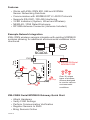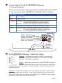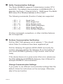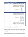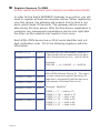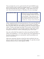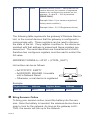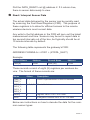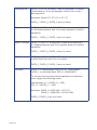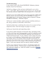
1
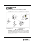
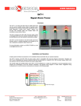
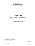
KWJ-WSN Wireless Sensors Serial MODBUS (RTU/ASCII) Gateway Quick Start Guide For Version 2.2 View the full user’s guide at www.kwjengineering.com. Information to Users This equipment has been tested and found to comply with the limits for a Class B digital devices, pursuant to Part 15 of the FCC Rules. These limits are designed to provide reasonable protection against harmful interference in a residential installation. This equipment generates, uses, and can radiate radio frequency energy and, if not installed and used in accordance with the instruction manual, may cause harmful interference to radio communications. However, there is no guarantee that interference will not occur in a particular installation. If this equipment does cause harmful interference to radio or television reception, which can be determined by turning the equipment off and on, the user is encouraged to try to correct the interference by one of more of the following measures: • Reorient or relocate the receiving antenna • Increase the separation between the equipment and receiver • Connect the equipment into an outlet on a circuit different from that to which the receiver is connected. • Consult the dealer or an experienced radio/TV technician for help. WARNING: Changes or modifications not expressly approved by Monnit could void the user’s authority to operate the equipment. RF EXPOSURE WARNING: To satisfy FCC RF exposure requirements for mobile transmitting devices, a separation distance of 20 cm or more should be maintained between the antenna of this device and persons during device operation. To ensure compliance, operations at closer than this distance are not recommended. The antenna used for this transmitter must not be co-located in conjunction with any other antenna or transmitter. Inside the Box You should find the following items in the box: • KWJ-WSN Serial MODBUS Gateway • Antenna • KWJ-WSN Wireless Sensors • Batteries • Mounting Hardware • Users Guide Some setup is required before the system will begin working. Please follow the instructions in this guide to correctly setup your system. Features • Works with KWJ-WSN 900, 868 and 433MHz Sensor Networking Solutions • Communicates with MODBUS RTU / ASCII Protocols • Supports RS-232C / RS-485 Interfacing • 3 LED Indicators (System, Wired and Wireless) • NEMA 4X / IP65 Rated Enclosure • RP SMA Antenna Connector (Antenna Included) Example Network Integration KWJ-WSN wireless sensors integrate with existing MODBUS systems allowing for additional environmental variables to be monitored. SCADA PLC Temp Pump E-1 Valve Control Activity Level Pump Control SMG Tank Voltage Water Leak KWJ-WSN Serial MODBUS GW Over 30 unique types of wireless sensors designed to monitor various environmental conditions. KWJ-WSN Serial MODBUS Gateway Quick Start • Attach Hardware • Verify COM Settings • Perform Communication Verification • Register Sensors to SMG • Bring Sensors Online PAGE 2 Connecting to the Serial MODBUS Gateway 1. Connect Antenna 2. Use communication select jumper to set RS-485 or RS-232C 3. Connect wires from MODBUS to SCADA / PLC / Master SMG 5-Wire Connector Red: 4.5 – 36VDC Black: Power ground Orange: RS-232C: TXD gateway’s transmitter data connection. Connect the MODBUS master’s receiver. RS-485: D+ Non-inverting 485 transmitter/receiver. White: Signal ground, internally connected to power ground. Green: RS-232C: RXD gateway’s receiver data connection. Connect the MODBUS master’s transmitter. RS-485: D- Inverting 485 transmitter/receiver. Reset Jumper Green - Receive White - Signal Ground Orange - Transmit Black - Power Ground Red - 4.5 - 36 VDC RS-485 / RS-232C Select Serial MODBUS Gateway - Indicator Lights System - Indicates gateway status. A green light indicates ready and working, a red light indicates L System there is a hardware problem. Wired L Serial MODBUS Gateway Wireless L Wireless Sensors Wired - for Indicates connectivity with MODBUS system. A green light indicates ready and working, a red light indicates there is a problem. A flashing green light indicates active communication. Wireless - Indicates wireless sensor network activity. A green light indicates ready and working, a red light indicates that no network has been formed (no sensors are registered). A flashing green light indicates radio traffic from the sensors. PAGE 3 Verify Communication Settings The Serial MODBUS supports 2 transmission modes: RTU and ASCII. The default communication is MODBUS-RTU, 8 data bits, No Parity, 1 Stop bit (8-N-1), 19200 baud. The MODBUS slave ID or Modbus address is 99 or 0x63. The following commands (Function Codes) are supported: • FC = 1: • FC = 5: • FC = 15: • FC = 3: • FC = 6: • FC = 16: Read Coils Write Single Coil Write Multiple Coils Read Holding Registers Write Single Register Write Multiple Registers All other commands, exceptions, or other interface features are not supported. Perform Communication Verification Poll the WACTIVE gateway coil at address 1. This should return False if no sensors have been registered yet. Poll the Gateway ID registers 40002-40003 and verify the number returned matches the Gateway ID on the bottom of your serial MODBUS gateway (4 digit number near the bar code). If the device times-out or gives some other error, please see the KWJ-WSN Serial MODBUS Gateway User’s Manual for example MODBUS communications. Change Communication Settings If you prefer to use different communication settings than the default, follow the instructions on the next page. Otherwise, skip to the next section. PAGE 4 Register Name Address Description BAUDRATE 40007 Designates the baud rate used by the MODBUS interface. After modifing this register, a gateway reset must be performed before changes can take effect. Value Represented 0 1 2 3 (DEFAULT) 4 5 6 COMMODE 40008 Designates the operating mode used by the MODBUS interface. After modifing this register, a gateway reset must be performed before changes can take effect. Value Represented 0 1 (DEFAULT) 2 3 4 5 6 ADDRESS 40009 Baud Selected 2400 4800 9600 19200 38400 57600 115200 Meaning RTU : 8-N-2 RTU : 8-N-1 RTU : 8-E-1 RTU : 8-0-1 ASCII : 7-N-2 ASCII : 7-E-1 ASCII : 7-O-1 Designates the MODBUS Address used in the communications interface. Values range from 1-247. Default value is 99. Modifying this register will result in a gateway reset. Once you have written your new settings, you will have to perform a reset for the settings to take effect. To perform a reset, write the “RST_DEVICE” Gateway Coil @ address 3 to TRUE. The device will reset one second after receiving this command. Your new communication settings will be in effect. To verify them, attempt to read the Gateway ID from registers 40002 - 40003 PAGE 5 Register Sensors To SMG DO NOT INSERT BATTERIES UNTIL SENSOR HAS BEEN REGISTERED. In order for the Serial MODBUS Gateway to go active, you will need to register at least one wireless device. When registering your first device, the gateway will need to time to form a network, which takes 30 seconds. The gateway will be unavailable during this time period. After the first device registration is complete, any subsequent registrations can be one right after the other, as the network only needs to form once. Each KWJ-WSN device has a 32 bit serial identifier and a 6 digit verification code. Fill in the following registers with this information. WDREG_ID_H 40016 WDREG_ID_L 40017 Wireless Device’s Identification Number of a device that will be registered to the gateway’s Wireless Device List. (UInt32 value) Example: 5005145 → _H = 0x004C, _L = 0x5F59. WDREG_CODE_1 40018 WDREG_CODE_2 40019 WDREG_CODE_3 40020 WDREG_CODE_4 40021 WDREG_CODE_5 40022 WDREG_CODE_6 40023 PAGE 6 A string security code unique to a specific KWJ-WSN Wireless Device ID. This value is cross-referenced against the device ID registers to successfully add the device to the gateway’s Wireless Device List. Example: “IMARVD” CODE_1 = “I” → 0x49 or 73 CODE_2 = “M” → 0x4D or 77 CODE_3 = “A” → 0x41 or 65 CODE_4 = “R” → 0x52 or 82 CODE_5 = “V” → 0x56 or 86 CODE_6 = “D” → 0x44 or 68 Then actuate this coil to verify that the ID and CODES were input correctly and to add the wireless device. If successful, the coil write will also be successful. If the codes are incorrect, the coil write will return a “Modbus IO error message”. REG_DEVICE_NOW 7 Writing True (1) to this coil will cause the register values located in WDREG_ ID_H/L and WDREG_CODE1/2/3/4/5/6 to be evaluated. If the values are correct, the device specified will be added to the Wireless Device List at the next available slot. Always read as False (0). When registering the first wireless device, the second LED will go red signifying there is no wired communication available, then the third LED will start flashing while the wireless network resets. Please wait approximately 30 seconds (until all LEDs turn green, signifying a successful network reset) after registering the first device, before attempting any other tasks. You can verify that the network is active by polling the WACTIVE coil at address 1. If it now returns true, the registration of the first wireless device is successful, and the wireless network is now active. Add more wireless devices using the same method, but you will not need to wait 30 seconds after each. To see the current wireless device count, read register 40004. PAGE 7 WD_CNT 40004 Wireless Device Count – Value that can be read to discover the number of registered sensors are configured to operate on the gateway. A value 0 – 100 is permitted. (READ-ONLY) Example Value: 0 (no sensors registered, factory reset condition) Example Value: 10 (10 Registered device) The following table represents the gateway’s Wireless Device List, or the current devices that the gateway is configured to communicate with. These registers can be read to discover the state of the list. If any register is written to, the device associated with that address is erased and these registers are zeroed out. The serial identifiers are formatted as a UInt32, therefore two contiguous registers must be read to extract the full value. ADDRESS FORMULA = 40101 + (2*WDL_SLOT) List entries can be as follows: Example: + _ • 0xFFFFFFFF: EMPTY • 0x00000000: ERASED, Unusable until a Network Reset • Otherwise, a real device is registered Register Name Address Register Name Address WDL [0] 40101 WD [99] 40299 Bring Sensors Online To bring your sensors online, insert the battery into the sensors. Once the battery is inserted, the wireless device does a scan to look for the network. As long as the gateway is ACTIVE, the sensor will link up to the network. PAGE 8 Poll the DATA_READY coil @ address 2. If it returns true, there is sensor data ready to view. Read / Interpret Sensor Data The actual data delivered by the sensor can be quickly read by scanning the Fast Read Registers (FRR). The purpose of these registers is to allow for efficient access to the remote wireless device’s most current data. Any write to the fist address in the FRR will zero out the latest measurement and time. Sensors may be set to report data in ten second intervals out of the box, but typically should be at 10 minute intervals by default. The following table represents the gateway’s FRR: ADDRESS FORMULA = 41001 + (8*WDL_SLOT) Example: Record Name Address Record Name Address FRR [0] 41001 FRR [99] 41793 These records consist of eight (8) registers per wireless device. The format of these records are: Name Offset Description TIME_H, TIME_L 0, 1 UInt32 representation of time in seconds DATA_0, DATA_1, DATA_2, DATA_3 2, 3, 4, 5 See table below. Battery 6 register value / 100 = x.xx Volts RSSI 7 a negative number from -20 to -110 dBm Below are instructions on how to decode the data for five common sensor types: PAGE 9 Temperature DATA_0: INT16, SIGNED. Data is recorded in Celsius. Divide data by 10 to get degrees Celsius out to one decimal point. Example: Data=271. 271/10 = 27.1°C DATA_1, DATA_2, DATA_3 are not used. Water DATA_0: UINT16, UNSIGNED. Data is recorded as 0 for no water present and 1 for water present in default operation. DATA_1, DATA_2, DATA_3 are not used. Open / Closed DATA_0: UINT16, UNSIGNED. Data is recorded as 1 for magnet present and 0 for magnet absent in default operation. DATA_1, DATA_2, DATA_3 are not used. PIR DATA_0: UINT16, UNSIGNED. Data is recorded as 1 for motion detection and 0 for no motion. DATA_1, DATA_2, DATA_3 are not used. Humidity DATA_0 is Temperature Data, INT16, UNSIGNED. DATA_1 is Humidity Data. INT16, UNSIGNED. To convert the humidity and temperature to standard units, apply the following math: Temperature_C = (DATA_0 ÷ 100) RH_% = (DATA_1 ÷ 100) Example: DATA_0: 2374/100 = 23.74°C DATA_1: 5289/100 = 52.89 %RH DATA_2, DATA_3 are not used. PAGE 10 Troubleshooting If you cannot talk to the Serial MODBUS Gateway, please double check the following: Verify the voltage on the red wire interfaced to our unit is 4.5V – 36.0 VDC. When powering the device you should see the startup indicator lights flash red and green for ~4 seconds. Verify the top and middle lights are green and the middle light flashes when communicating with the MODBUS master. If the middle light is not green, please refer to Section 2 Serial MODBUS Gateway – Indicator Lights. Verify your communication select jumper matches what you are using, whether its RS-485 or RS-232C. Verify the data lines, matching the colors of our wires to their respective lines. See the image on page 3 to verify. Verify your baud rate and operating mode. If you have made changes to the baud rate, operating mode, or other and have lost communication, perform a factory reset, by opening up the Serial MODBUS gateway and finding the COM reset and jumper. To do a factory reset, apply the jumper. Power on the gateway. Deliberately remove and replace the jumper twice. All indicator lights will flash red quickly (5x / sec) when the device has been successfully reset. Unpower the gateway and remove the jumper. After powering the gateway again, it will now operate with the factory default settings. If there is an internal memory failure, all indicator lights will stay red after startup. If this occurs, contact KWJ Engineering customer support at 1-800-472-6626 or email at sales@ kwjengineering.com. PAGE 11 For additional information or more detailed instructions on how to use your KWJ-WSN Serial MODBUS Gateway or KWJ-WSN Wireless Sensors, please view our support information and documentation on the web at http://www.kwjengineering.com. View the full user’s guide at www.kwjengineering.com. KWJ WSN, SPEC are trademarks of KWJ Engineering Inc. ©2014 KWJ Engineering Inc. All Rights Reserved. KWJ Engineering Inc 8430 Central Ave. Suite C Newark, CA 94560 510-794-4296 www.kwjengineering.com