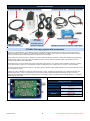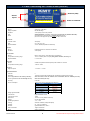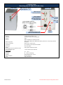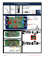
1
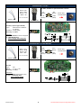
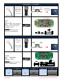
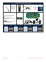
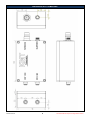
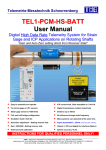
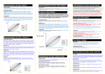
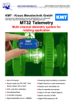
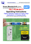
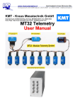
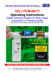
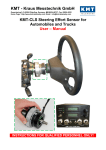
KMT - Kraus Messtechnik GmbH Gewerbering 9, D-83624 Otterfing, Germany, 08024-48737, Fax. 08024-5532 Home Page: http://www.kmt-telemetry.com, Email: [email protected] CT2-Mini User manual INSTRUCTIONS FOR QUALIFIED PERSONNEL ONLY! General functions: DC power cable DEC CT2-Mini Decoder/ Receiver 2 x Sensor cables 2m CT2-Mini Encoder/ Transmitter Receiving 1x antenna AC/DC power supply for Decoder (Option) DC power cable ENC Diversity receiver contain 2x antenna! Hexagon screw driver to open the CT-Mini-ENC CT2-Mini Telemetry system with accessories CT2-Mini is a 2-channel telemetry system designed for easy mounting onto rotating and moving parts to provide non-contact transmission of measured parameters such as pressure, force, temperature, acceleration and voltage. Also for point to point application like bridge or buildings testing, you can install CT2 Mini instead long cables from the sensor to the Computer. Sensors inputs are connected via screw on, waterproof connectors. Measured values are prepared in analog format, digitized and transmitted via radio frequencies. Different carrier frequencies are provided, this allows up to four systems to operate in parallel. The complete transmitter assembly is waterproofed to IP65 specifications. The following sensors can be connected to the system: (STG) Strain gages sensors in full-, and half- bridge configuration (350 ohm or greater), Type K Thermocouples to 1000°C, ICP, potentiometers sensors and capacitive sensors. Voltage inputs of +/-5V and +/-10V are available. The measured values are processed and output as +/-5V analog signals at the BNC sockets (optional digital output for special PCM interface into a PC) on the stationary receiver. Resolution of 12 bits is standard; this enables an amplitude dynamic of 72 dB. The analog signal bandwidth is up to 12000Hz (see table). The measurement accuracy is +/-0.25 % (without sensor). The CT2-Mini is suited for operation at ambient temperatures of -20 to +70°C. The transmission distance between transmitter and receiving antenna is of the order of 250* m (*40kbit with10mW transmitting power – non diversity) With diversity only 100m range Cut off frequency from anit-aliasing filter scanning rate (see red) Bit rate per channel 40 kbit/s 375 Hz (-3dB) (1428 Hz) 3000 Hz (-3dB) (11428 Hz) 6000 Hz (-3dB) (22857 Hz) 12000 Hz (-3dB) (45714 Hz) 320 kbit/s 640 kbit/s 1280 kbit/s Version 2013-05 2 Technical Data are subject to change without notice! CT2 Mini Transmitting Unit Technical Data (Encoder) Antenna (TNC) Sensor inputs Power In 6-30V DC Untwist to open the housing CT-STG-V2: Sensor: strain gage, > 350 Ohms Bridge completion: full and half bridge Excitation: 4 VDC (fixed), short-circuit protection Gain: 250-500-1000-2000 selectable by solder jumpers (CT-STG-V1 only with Gain 200-1000 ) Offset Zero adjustment by potentiometer or optional Auto-zero function (which is not lost by power-off), offset range up to 80% of full scale. CT-ICP-V2: Constant current: 4mA (fixed) Gain: 2x, 4x, 8x, 16x or 32x Signal bandwidth: 3 Hz to 12000Hz (depended of transmitter!) CT-POT: Sensor: Potentiometer Sensor >350 Ohms to 10kOhms Excitation: 4 VDC (fixed) CT-TH-K-ISO: Sensor: thermo-couple, type K ( with cold junction compensation) Temperature measuring range: -50°C to +1000°C (other on request) with galvanic isolation, Accuracy 1% Signal bandwidth: 0...10 Hz -3dB CT-PT100: Sensor: resistance temperature detectors (RTDs) with resistance of 100 ohm Temperature measuring range: -100°C to +500°C CT-VOLT: High-level inputs: +/- 5 Volt or +/- 10 Volt System Parameters: Channels: 2 Resolution: 12 bit A/D converter with anti aliasing filter, simultaneous sampling of all channels Line-of-sight distance with diversity telemetry: 200m with 40kbit, 150m with 320/kbit, 100m with 640kbit, 50m with 1280kibt (free view) Line-of-sight distance with non-diversity telemetry: 500m with 40kbit (free view) Powering: 6-30 V DC Cut off frequency from anit-aliasing filter 100 mA at(-3dB) 12V using 2 STG sensorsrate at 350 Ohms and scanning (red) Power consumption: Bit rate 1280 kbit/s 640 kbit/s 320 kbit/s 40 kbit/s Analog signal bandwidth: 2 Channels 12000 Hz (45714 Hz) 6000 Hz (22857Hz) 3000 Hz (11428 Hz) 375 Hz (1428 Hz) Transmission: Digital PCM Miller Format Transmission Power: 10mW Dimensions: 102 x 68 x 41 mm (without connectors) Weight: 0.45 kg without cables Operating temperature: - 20 … +70°C Housing: Aluminum anodized, waterproofed (IP65) Humidity: 20 ... 80% no condensing Vibration: 5g Mil Standard 810C, Curve C Static acceleration: 100g in all directions Shock: 200g in all directions Version 2013-05 3 Technical Data are subject to change without notice! Technical data: Receiving Unit CT2-Mini DEC (Decoder) Front view Back view BNC socket for analog signal outputs 1 … 2 TNC-socket for receiving antenna TNC-socket for receiving antenna Optional at diversity with active LED Field strength indicator Power ON LED 7- pole TUCHEL-socket for Voltage supply cable (10–30V) Sync-Loss Indicator LED shine at bad transmission ON/OFF switch System Parameters: Channel: 2 analog outputs via (BNC) +/-5V Resolution: 12 bit D/A converter, with smoothing filter Dynamic: 72dB Receiver 40kbit standard with not diversity receiver 40kbit, 320kbit, 640kbit and 1280kbit with diversity receiver incl. two receiving antennas! Power supply input: 10-30 VDC Current consumption: 300mA at 10V, 100mA at 30V Frequencies: up to 4 different carrier frequencies available Dimensions: 105 x 105 x 65mm Weight: 0.60 kg without cables and antenna Overall system accuracy between encoder input and decoder output: +/-0.25% without sensor influences Environmental Operating: -20 … +70°C Humidity: 20 ... 80% not condensing Vibration: 5g Mil Standard 810C, Curve C Static acceleration: 10g in all directions Shock: 100g in all directions Version 2013-05 4 Technical Data are subject to change without notice! Connection, STG bridge configuration: CT2-Mini ENC (encoder) STG module Type: Strain gage >350 Ohms Excitation: 4 VDC (fixed) Gain: 200 or 1000 Accuracy +/- 0.25% Black = IN White = IN + Brown = +EXC Blue = --EXC Sensor socket Sensor cable 1/1 or 1/2 Bridge setting + IN (White) -- IN (Black) + EXC (Brown) -- EXC (Blue) Zero via Potentiometer (standard) Sensor plug CT2-Mini ENC Auto Zero Switch (option) Only for STG Antenna OUT (TNC) Powering GND (Black) 10-30VDC (Brown) NC CT-STG-Version V1 Gain 200 or 1000 by solder bridge Gain 1000 Gain 200 CT-STG-Version V2 Gain 250-500-1000 or 2000 by jumper or on request 1000-2000-4000-8000 Gain 1000-2000-4000-8000 on request! Version 2013-05 5 Technical Data are subject to change without notice! Connection CT-POT: CT-POT module for potentiometer sensors Black = NC* Blue = GND Brown = +4V White = IN IN (White) NC (Black) +4V (Brown) GND (Blue) Sensor plug CT2-Mini ENC *NC= not connected Sensor cable Sensor socket CT-POT (=special type off STG) Type: Potentiometer >350Ohm to 10kOhm Excitation: 4 VDC (fixed) Accuracy +/- 0.25% Half bridge setting Attention: The POT modules must be configured as a Half Bridge Unit. Don’t change offset and gain!! Connection CT-Volt module Black = IN +/White = GND Brown = NC* Blue = NC* GND (White) IN +/(Black) NC* (Brown) NC* (Blue) Sensor plug CT2-Mini ENC *NC= not connected Sensor cable Sensor socket CT-Volt Type: Volt Range: +/-5 or +/-10V Accuracy +/- 0.25% Half bridge setting Attentions: At Volt modules must plug the plug bridge on Half Bridge Unit. Don’t change offset!! Version 2013-05 +/-10V +/-5V 6 Technical Data are subject to change without notice! Connection CT-ICP module GND (White) Black = IN +/White = GND Brown = NC* Blue = NC* NC* (Brown) IN +/(Black) Sensor plug CT2-Mini ENC NC* (Blue) *NC= not connected Sensor socket Sensor cable Gain: 32 16 8 4 2 CT-ICP Type: ICP Signal bandwidth: 3Hz to (see table) Gain: 2x, 4x, 8x, 16x or 32x Constant current: 4mA (fixed) Half bridge setting Accuracy +/- 0.25% Attentions: At ICP modules must plug the plugbridge on Half Bridge Unit. Connection CT-Pt100 module (RTDs) Black = IN Connected with GND (White) brown IN (Black) Sensor plug White = GND IN (Brown) Connected with Blue Sensor cable CT-Pt100 Type: RTD 100 ohm Range: -100 to 500°C Accuracy +/- 0.25% Sensor socket CT2-Mini GND (Blue) ENC Half bridge setting Attentions: At Pt100 modules must plug the plug bridge on Half Bridge Unit. Temperature [°C] -100 -50 0 50 100 Version 2013-05 Output [V] -0,997 -0,497 0,001 0,499 1,000 Temperature [°C] 150 200 250 300 350 Output [V] 1,500 2,001 2,501 3,001 3,501 7 Temperature [°C] 400 450 500 Output [V] 4,004 4,498 4,999 Technical Data are subject to change without notice! Connection TH-K ISO Thermo couple GND (White) Black = IN +/White = GND Brown = NC* Blue = NC* NC* (Brown) IN + (Black) Sensor plug CT2-Mini ENC NC* (Blue) *NC= not connected Sensor socket Sensor cable CT-THK-ISO - Galvanic isolated! Type: K Range: -50°C – 1000°C Bandwidth: 0-20Hz (more on request) Accuracy +/-1% Half bridge setting Attentions: At Thermo couple must plug the plug bridge on Half Bridge Unit. Temperature [°C] -50 0 50 100 150 200 Version 2013-05 Output [V] -0.220 0.013 0.254 0.504 0.752 0.992 Temperature [°C] 250 300 350 400 450 500 Output [V] 1.236 1.482 1.734 1.990 2.242 2.498 Temperature [°C] 550 600 650 700 750 800 8 Output [V] 2.754 3.010 3.266 3.519 3.700 4.015 Temperature [°C] 850 900 950 1000 Output [V] 4.262 4.506 4.746 4.980 Technical Data are subject to change without notice! Dimensions of CT2-MINI-ENC Version 2013-05 9 Technical Data are subject to change without notice! Kraus Messtechnik GmbH Gewerbering 9, D-83624 Otterfing, +49-8024-48737, Fax. +49-8024-5532 – Germany Home Page http://www.kmt-gmbh.com E-mail: [email protected] Konformitätserklärung Declaration of Conformity Declaration de Conformité Wir We Nous KMT - Kraus Messtechnik GmbH Anschrift Address Adress Gewerbering 9, D-83624 Otterfing, Germany erklären in alleiniger Verantwortung, daß das Produkt declare under our sole responsibility, that the product declarons sous notre seule responsibilité, que le produit Bezeichnung Name Nom Messdatenübertragungssystem Typ,Modell,Artikel-Nr., Größe Type,Model, Article No.,Taille Type, Modèle, Mo.d'Article,Taille CT2, CT4, CT8, CT16 mit den Anforderungen der Normen und Richtlinien fulfills the requirements of the standard and regulations of the Directive satisfait aux exigences des normes et directives 108/2004/EG Elektromagnetische Verträglichkeit EMV / EMC DIN EN 61000-6-3 Ausgabe 2002-8 Elektromagnetische Verträglichkeit EMV Teil 6-3 Fachgrundnorm Störaussendung DIN EN 61000-6-1 Ausgabe 2002-8 Elektromagnetische Verträglichkeit EMV Teil 6-1 Fachgrundnorm Störfestigkeit und den angezogenen Prüfberichten übereinstimmt und damit den Bestimmungen entspricht. and the taken test reports und therefore corresponds to the regulations of the Directive et les rapports d'essais notifiés et, ainsi, correspond aux règlement de la Directive. Otterfing, 30.05.2006 Martin Kraus Ort und Datum der Ausstellung Place and Date of Issue Lieu et date d'établissement Name und Unterschrift des Befugten Name and Signature of authorized person Nom et signature de la personne autorisée Version 2013-05 10 Technical Data are subject to change without notice!