1
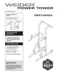
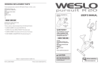
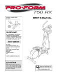
PART IDENTIFICATION CHART
Use the drawings below to identify the small parts needed for assembly. The number in parentheses below each
drawing is the key number of the part, from the PART LIST near the end of this manual. The number following the
key number is the quantity needed for assembly. Note: If a part is not in the hardware kit, check to see if it
has been preassembled. Extra parts may be included.
M6 Locknut
(51)–4
M8 Split
Washer
(42)–8
M4 x 16mm
Screw (47)–8
M8 Locknut
(10)–10
M8 Small
Washer
(93)–4
Wave Washer
(81)–4
M10 Locknut
(48)–1
M8 Large
Washer (54)–4
M10 Split
Washer (98)–2
M8 x 13mm
Screw (95)–6
M6 x 30mm
Bolt (49)–4
M6 Curved
Washer
(25)–4
M10 Curved
Washer (39)–3
M8 x 20mm
Screw (34)–4
M8 x 65mm Bolt (94)–2
M8 x 40mm Bolt (83)–6
M8 x 125mm Bolt (58)–2
M10 x 25mm
Screw (96)–1
M10 x 54mm Screw (97)–1
M10 x 65mm Screw (40)–4
M10 x 60mm Bolt (61)–1
6
MAINTENANCE AND TROUBLESHOOTING
MAINTENANCE
Note: For clarity, the right shield is shown removed in
the drawing below.
Inspect and tighten all parts of the hybrid trainer
regularly. Replace any worn parts immediately.
Next, locate the Reed Switch (43). Loosen, but do not
remove, the M4 x 12mm Screw (31).
To clean the hybrid trainer, use a damp cloth and a
small amount of mild soap. IMPORTANT: To avoid
damage to the console, keep liquids away from
the console and keep the console out of direct
sunlight.
31 38
24
CONSOLE TROUBLESHOOTING
Most console problems are the result of low batteries.
See assembly step 13 on page 13 for replacement
instructions.
43
If the console does not display your heart rate when
you use the handgrip heart rate monitor, see step 5 on
page 19.
HOW TO ADJUST THE REED SWITCH
If the console does not display correct feedback, the
reed switch should be adjusted.
To adjust the reed switch, see EXPLODED DRAWING
A on page 26. Remove the M4 x 16mm Screws (47)
and the M4 x 25mm Screws (41) from the Left and
Right Shields (17, 18). Make sure to note which size
of Screw you remove from each hole. Then, gently
move the Right Shield out of the way.
Next, rotate the Pulley (24) until a Magnet (38) is
aligned with the Reed Switch (43). Slide the Reed
Switch slightly toward or away from the Magnet. Then,
retighten the M4 x 12mm Screw (31).
Rotate the Pulley (24) for a moment. Repeat these
actions until the console displays correct feedback.
When the reed switch is correctly adjusted, reattach
the shields.
21
HOW TO ADJUST THE DRIVE BELT
If you can feel the pedals slip while you are pedaling,
even when the resistance is adjusted to the highest
level, the drive belt may need to be adjusted.
To adjust the drive belt, see EXPLODED DRAWING A
on page 26. Remove the M4 x 16mm Screws (47)
and the M4 x 25mm Screws (41) from the Left and
Right Shields (17, 18). Make sure to note which size
of Screw you remove from each hole. Then, gently
move the Left Shield out of the way.
35
Note: For clarity, the left shield is shown removed in
the drawing at the right.
46
Loosen the M6 x 20mm Hex Screw (46). Then, tighten
the M10 x 50mm Hex Screw (66) until the Drive Belt
(35) is tight.
66
When the Drive Belt (35) is tight, tighten the M6 x
20mm Hex Screw (46). Then, reattach the shields.
22
SUGGESTED STRETCHES
The correct form for several basic stretches is shown at the right. Move slowly as you stretch; never bounce.
1. Toe Touch Stretch
Stand with your knees bent slightly and slowly bend forward from
your hips. Allow your back and shoulders to relax as you reach down
toward your toes as far as possible. Hold for 15 counts, then relax.
Repeat 3 times. Stretches: Hamstrings, back of knees and back.
1
2. Hamstring Stretch
Sit with one leg extended. Bring the sole of the opposite foot toward
you and rest it against the inner thigh of your extended leg. Reach
toward your toes as far as possible. Hold for 15 counts, then relax.
Repeat 3 times for each leg. Stretches: Hamstrings, lower back and
groin.
2
3. Calf/Achilles Stretch
With one leg in front of the other, reach forward and place your
hands against a wall. Keep your back leg straight and your back foot
flat on the floor. Bend your front leg, lean forward and move your
hips toward the wall. Hold for 15 counts, then relax. Repeat 3 times
for each leg. To cause further stretching of the achilles tendons,
bend your back leg as well. Stretches: Calves, achilles tendons and
ankles.
3
4
4. Quadriceps Stretch
With one hand against a wall for balance, reach back and grasp one
foot with your other hand. Bring your heel as close to your buttocks
as possible. Hold for 15 counts, then relax. Repeat 3 times for each
leg. Stretches: Quadriceps and hip muscles.
5. Inner Thigh Stretch
Sit with the soles of your feet together and your knees outward.
Pull your feet toward your groin area as far as possible. Hold for 15
counts, then relax. Repeat 3 times. Stretches: Quadriceps and hip
muscles.
24
5
PART LIST
Model No. PFCCEL03812.1 R0714A
Key No. Qty.
Description
Key No. Qty.
Description
1
2
3
4
5
6
7
8
9
10
11
12
13
14
15
16
17
18
19
20
21
22
23
24
25
26
27
28
29
30
31
32
33
34
35
36
37
38
39
40
41
42
43
44
45
46
47
48
49
50
Rear Frame
Front Stabilizer
Upper Body Arm Cap
Wheel
Snap Ring
Rear Stabilizer
Seat Handle Cap
Rear Stabilizer Cap
Console Knob
M8 Locknut
Seat Frame Cap
Seat
Leg Bushing
Left Seat Bracket
Right Seat Bracket
Console
Left Shield
Right Shield
Leg Cap
Seat Frame Cap
Crank
Clamp
Front Frame
Pulley
M6 Curved Washer
Seat Handle Grip
Water Bottle Holder
Idler Screw
Front Frame Bumper
Resistance Motor
M4 x 12mm Screw
M6 Washer
M10 x 98mm Bolt
M8 x 20mm Screw
Drive Belt
M8 x 10mm Screw
Eddy Mechanism
Magnet
M10 Curved Washer
M10 x 65mm Screw
M4 x 25mm Screw
M8 Split Washer
Reed Switch/Wire
Crank Bearing
Main Wire Harness
M6 x 20mm Hex Screw
M4 x 16mm Screw
M10 Locknut
M6 x 30mm Bolt
Upper Body Arm Grip
51
52
53
54
55
56
57
58
59
60
61
62
63
64
65
66
67
68
69
70
71
72
73
74
75
76
77
78
79
80
81
82
83
84
85
86
87
88
89
90
91
92
93
94
95
96
97
98
*
M6 Locknut
M6 x 38mm Bolt
Handlebar
M8 Large Washer
M4 x 5mm Screw
Carriage Bushing
Large Bumper
M8 x 125mm Bolt
Seat Handle
Backrest
M10 x 60mm Bolt
Idler
Pivot Bushing
Right Pedal Carriage
Left Pedal Carriage
M10 x 50mm Hex Screw
Pedal
Pulse Grip/Pulse Wire
Small Bumper
Pedal Knob
Right Pedal Leg
Crank Arm
Console Post
Left Upper Body Leg
Right Pedal Leg Bracket
Left Pedal Leg Bracket
Crank Arm Screw
Crank Arm Cap
Left Pedal Leg
Axle
Wave Washer
Upper Body Arm Cover
M8 x 40mm Bolt
Pedal Plate
Pedal Brace
Right Upper Body Leg
M10 x 102mm Bolt
Right Upper Body Arm
Left Upper Body Arm
Pivot Cover
Ground Screw
M4 x 10mm Screw
M8 Small Washer
M8 x 65mm Bolt
M8 x 13mm Screw
M10 x 25mm Screw
M10 x 54mm Screw
M10 Split Washer
User’s Manual
1
1
2
2
2
1
2
2
1
16
4
1
2
1
1
1
1
1
2
2
1
1
1
1
4
2
1
1
1
1
7
9
2
10
1
8
1
2
3
4
5
12
1
2
1
1
17
5
4
2
4
8
1
6
8
4
2
2
2
1
1
1
14
1
1
1
2
2
6
2
1
2
1
1
1
1
2
2
1
1
6
2
6
2
2
1
2
1
1
6
1
1
4
2
6
1
1
2
–
Note: Specifications are subject to change without notice. For information about ordering replacement parts, see
the back cover of this manual. *These parts are not illustrated.
25
34
59
14
26
26
40
8
42
38
11
47
10
6
10
24
38
1
91
5
44
35
8
47
10
32
66
32 28
20
11
46
52
21
93
52
32
60
69
62
20
31
52
5
43
15
61
37
52
11
22
10
30
44
32
32
31
49
96
45
25
27
93
63
59
47
58
51
11
92 29
48
23
39
98
98
39
97
47
12
41
26
4
7
63
17
2
40
47
41
41
41
41
18
4
EXPLODED DRAWING A
Model No. PFCCEL03812.1 R0714A
27
72
76
63
77
81
78
72
79
75
67
63 54
65
89
42
95
90
13
34
74
82
50
3
56
47
55
69
71
34
64
47
69
90
54
56
70
55
48
63
81
48
36
63
80
10
16
67
73
33
85
87
31
36
57
84
81
39
81
9
63
47
53
13
82
68
83
50
42
19
86
90
10
54
63
34
94
68
10
83
88
3
47
EXPLODED DRAWING B
Model No. PFCCEL03812.1 R0714A