1
966R
Next Generation Remote Multi-Channel Test Instrument
Hardware/Command Line Software
User Manual
Sage Instruments • 966R User Manual • Contents
Overview
Purpose...........................................................................4
Capabilities..........................................................................5
Typical Applications..............................................................4
Options.................................................................6
Unpacking...........................................................................7
Packout Contents.................................................................7
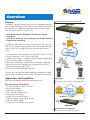
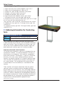
THE 966R is a powerful multi-channel IP
Telephony test server designed to provide
service providers and manufacturers a
robust test patform to remotely monitor,
turn-up, and maintain voice, fax and data
services.
Installation
Software Installation............................................................8
Physical Installation.............................................................10
Telnet Command Line Interface
Overview.......................................................................11
Table of Commands............................................................14
Technology and Applications
Voice Processing Impairments.............................................18
Test Metrics........................................................................19
Error States.........................................................................25
Running Tests
SMOS Director Test.............................................................28
SMOS Responder...............................................................30
Packet Voice Impaairment (PVIT) Test..................................31
Echo Sounder.....................................................................33
Echo Generator...................................................................35
INMD P.561........................................................................37
MoIP Director......................................................................39
FAX Transmit and Receive Tests............................................41
Digit Analyzer Test...............................................................42
Digit Sender Test.................................................................43
SAGE 966R Warraty..............................................44
In today’s environment, test tools need
to be cost-effective in both form and
function. And with it’s broad range of
instrument quality test features and it’s
ability to be configured as a single or multiuser platform, the 966R can be shared to
meet a variety of requirements in a
Next Generation environment.
• Field Certification & Deployment Testing
• Voice Quality Testing
• Tier III Fault Isolation
• Proactive Quality Assurance Testing
• Proactive IMT Testing (ROTL)
Sage Instruments • 966R User Manual • Overview
Purpose
Typical Applications and Configurations
The 966R is a powerful remote multi-channel IP Telephony precision
test instrument combining TDM, Ethernet and Analog interfaces and
simultaneous test capability to comprehensively test and monitor
Next Generation Networks in Real-Time.
• Voice Processing & IP Telephony Transparency design verification
• VoIP service readiness, turn-up testing, and trouble shooting
• Voip security monitoring
The 966R can generate one or many end-to-end test calls from the
packet, TDM, and/or Analog interfaces while monitoring the bearer
channel (TDM, RTP, Analog) to flush out real-time performance
issues.
• Passively and/or actively detect & measure AUDIO LEVELS & ECHO
• Assess voice quality - MOS, DELAY, NOISE, etc.
• Qualify Echo Cancellers - Dispersive Echo and programmable delay
• Verify FAX/data modem transparency
• Verify VAD, Jitter Buffer, Comfort Noise, and silence suppression • Emulate Fax and True IP phones with jitter buffers and real RTP
• Filter, decode and analyze RTP/RTCP
• Detect and monitor rogue/illigal VoIP calls
Whether you are a Next Generation operator or designer, the 966R
reduces rollout and design cycle time for new packet voice services.
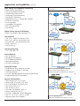
Applications and Capabilities
966R features a powerful Next Generation Voice Suite
Edge Network Service Qualification
(End-to-End Voice Quality & Troubleshooting)
Echo Cancellation Performance
• Passive Echo Monitor (INMD ITU-P.561)
• Multi-Echo Detection
• Echo Level, Echo Delay
• Echo Canceller Disabler Tone(s)
• Dispersive Echo Emulation
• Double Talk Test and Emulation
• Echo Cancellation Convergence Testing
• Echo Cancellation Depth
• G.168 Test Suite and Echo Can Control
Packet Tandem & LD Network
(Voice Quality, Fax & Data Transparency)
Sage Instruments • 966R User Manual • Applications and Capabilities (continued)
Voice Quality and Telephony Transparency
• Mean Opinion Score (MOS)
• One-way and Round Trip Delay
• Comfort Noise Level (CNG)
• Audio Level (Gain/Attenuation)
• Jitter Buffer Performance
• Packet/Frame Loss (% Average burst length)
• DTMF/MF Verification
• Fax Transparency
• V.xx Modem Transparency
• RTP Traffic Generation
• Call Loading
Typical Applications and Configurations
(continued)
Digital Facility Turn-up & Validation
• Multi-Channel BERT and Fractional E1/T1
Test Interfaces
• Two T1/E1 - 48/64 Simultaneous Tests
• Four T1/E1 - 96/124 Simultaneous Tests
• Dual 0/100 BT - 128 Simultaneous Tests
• Quad 2-wire FXO
• Dual 4-wire Dry
VoIP Pre-Qualification
(Generate and Monitor SIP and RTP Traffic)
Call Setup Signaling
• CAS • PRI-ISDN • SIP
Passive Monitor
• SIP Call Monitor
• RTP decode and Monitor
• RTCP decode and Monitor
• Echo Level and Delay
• PRI-ISDN Call Monitor
Standard Features
• Send/Measure Tone, Spectrum Analyzer
• Graphical User Interface PC Software
• PCM Data Capture
• Channel Selectable Remote and Local Audio Monitor
• Programmable Pass/Fail Parameters
Physical Characteristics
• Test Interface: 2/4 T1 or E1 Ports
• Bantam, BNC (Dual Mon, D&I, Term)
• Dual 10/100 BaseT, RJ-45 (Half, Full)
• Four 2-Wire FXO, RJ-11
• Two 4-Wire Dry, RJ-22
• Com Port: 10/100 BaseT, USB 1.0
• Power 120/240VAC; UL, CE
• Com Port: Single USB, Series B Receptacle
• Size 10” x 4 “x 14.5”, max wt. 10 lbs.
• Operating Temp 0-40 Degrees C
Access Gateway Design Verification
(Delay, Clarity, Echo Cancellers, etc.)
Generate, decode and Monitor SIP & RTP/RTCP
VoIP Pre-Qualification
(Generate and Monitor SIP and RTP Traffic)
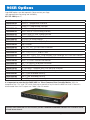
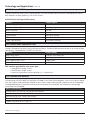
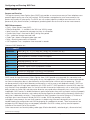
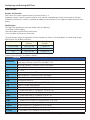
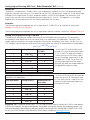
Sage Instruments • 966R User Manual • 966R Options
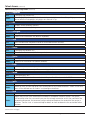
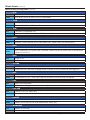
Sage 966R options are sold separately. Please contact your Sage
sales representative for pricing and availability.
831-761-1000 (press 2).
Part Id
Description
7966-0100-02
Dual E1/T1 programable interfaces
Quad E1/T1 programable interfaces
Dual Ethernet programable interfaces
Dual 2-Wire & 4-Wire Analog Interface
Quad 2-Wire & 4-Wire Analog Interface
Onboard TCP/IP Remote Controller
PRI-ISDN Call Setup Protocol
ITUG.107 Conversational Quality Test
Digit Analyzer
ROTL 100, 102, 105 Test Lines & Directors
MoIP Test Line & Director
BERT - DS0, DS1, FT1, and FE1 BERT
NGEN Tests - SMOS, PVIT, Echo Sounder, Echo Generator Test Lines and Directors
G.168 Suite - ITU G.168 Echo Canceller Conformance Test
INMD - ITU P.561 Passive Echo Monitor
Fax - T.30 Transmit & Reciever Emulation
SIP Protocol Mon/Decode
SIP Call Setup - Orig/Term plus Dual Spectrum Analyzer
RTP Mon & Decode plus Dual Spectrum Analyzer
One (1) year extended warranty.
Two (2) year extended warranty.
Three (3) year extended warranty.
7966-0200-02
7966-0300-02
7966-0400-02
7966-0450-02
7966-0800-02
7966-1000-02
7966-5000-02
7966-5100-02
7966-5200-02
7966-5300-02
7966-5400-02
7966-5500-02
7966-5600-02
7966-5700-02
7966-5800-02
7966-6110-02
7966-6120-02
7966-6130-02
796X-8980-01
796X-8980-02
796X-8980-03
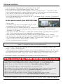
It is important to note that the SAGE 966R is a Telnet Command Line Controlled device. With the
exception of the “On” and “Off”switch there are no controls of any kind on the 966R unit itself. If the unit is
disconnected from the PC outputs are “idled” after 30 seconds.
Intuitive Telnet Command Line User Interface provides
of each bearer channel.
Remote Instrument Control with individual control
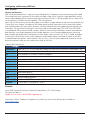
Sage Instruments • 966R User Manual • Unpacking
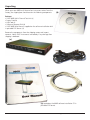
When your new 966R multi-channel test instrument arrives from the
factory, the shipping box should contain the following components:
(d)
Packout
• SAGE 966R Multi-Channel Test Unit (a)
• Power Cord (b)
• USB Cord (c)
• Software Compact Disk (d)
• SAGE 966R User Manual, supplied on the software installation disk
in printable PDF format. (e)
Remove the components from the shipping carton and inspect
contents. Notify SAGE Instruments immediately if any damage from
shipping is detected.
(a)
(b)
(c)
(e) Located on the 966R software installation CD in
printable PDF format.
Sage Instruments • 966R User Manual • 966R Software Installation
Remote Command
Important Note: The following instructions only apply to
966R Units Equipped with the Sage TCP/IP Telnet Remote
Command Interface.
Installation
1. To complete this procedure, you must have a Windows
98SE/2000/ME/XP PC compatible computer with a USB port, and the
software update file “960Asetup_0578.exe”.
Note: Windows 98SE users installing the 966R software for
the first time may be prompted to insert their Windows 98
Installation CD. If this prompt appears, the installation will not
proceed until software drivers are loaded from that CD.
Warning: If you are currently running Sage 960 software
prior to v5.7.8, your 960 configuration files may no longer
be useable due to a file format change. The installation
program will automatically create a new one for you.
Warning: DO NOT CONNECT the TCP/IP 960x USB port to
your PC USB port, yet. If you have previously made that
connection while both PC and 960x were powered up,
you must first go to the end of this document and
complete the section titled “If You Connected the TCP/IP
966R USB Too Soon” before proceeding to step 3 below.
2. If the 960B is not powered up, turn it on. Do not connect
ethernet or USB cables, yet.
3. If 960x software exists on the PC, you must UNINSTALL it now:
a. Go to Start, Control Panel, Add/Remove Programs, then double-click the Sage 960 entry and follow the on screen
instructions.
Note: If a Sage 960 entry does not appear in the PC Add/
Remove Programs list, you must manually delete the old 960
program subdirectory and its contents: Using Windows Explorer,
navigate to C:\Program Files\Sage Instruments, then delete the
subdirectory named “960”.
4. Launch the 966R software installer program:
4. Launch the 960 software installer program:
a. Using Windows Explorer, navigate to the subdirectory where
you previously placed the 960Asetup_06113eng.exe file
b. Double-click on the file. You may be presented a Security
Warning
window.onSimply
click
on “Run”.
Note:
Depending
your PC
operating
system version, the
Post Installation
Depending on your PC operating system
version, the software installer may prompt
you to reboot your PC before continuing
with the program.
Once the software installation is complete,
you may power up the 966R and conduct
tests .
installer may prompt you at some point to reboot your PC before
continuing with the install.
(continued on page 14)
Sage Instruments • 966R User Manual • Software Installation
(for 966R TCP/IP Remote enabled units) (continued)
c. You will now see a “Sage Instruments” splash screen; click on “Next”
d. You will now see the InstallShield opening screen; click on “Next”
e. The installer will now display the license agreement. Click on “I accept the terms....” then click on “Next”
f. You will now be presented the Customer Information screen. Fill in the User Name and Organization boxes
g. Then, click on “Anyone who uses this computer (all users)” and click on “Next”
h. The installer will now present the Custom Setup screen
i. Click on the drop-down box just to the left of the text “TCP/IP Remote Control”, and select “This feature will be installed on local hard drive”
At this point connect your 966R USB Cable
j. Click on “Next”
k. The Ready to Install screen will now appear. Click on “Install”
l. At completion of the installation, click on “Finish”
m. You will see a text file “remoteControlInstall.txt” displayed. Close that window.
n. The software installation will now proceed. When it is done, a new window titled “Set Up Microsoft ActiveSync 3.8” will appear.
o. Click “Next,” then click “Next” again. A “Copying File” window will open. The progress bar may pause at “92%” for 30 seconds to several minutes, depending on the speed of your PC.
p. After ActiveSync is installed, you may see a Windows Security Alert box appear. Click on “Unblock”
q. You will now see a “Get Connected” box. Connect the supplied USB cable between your PC and the 960B.
r. The “Found New Hardware Wizard” will appear. Choose “”No, not this time,” then click “Next”
s. Choose “Install from a list or specific location,” then click “Next”
t. Click on “Include this location in the search”
Note: If the following search path does not appear in the “location” window, CAREFULLY type it in (without quotes): “C:\Program Files\Sage Instruments\960\ce\drivers”
u. Click on “Next”. You may see an alert box that warns that the driver has not passed “Windows Logo testing...” Click on “Continue Anyway”
v. Once ActiveSync ‘sees’ the 960B, it will present a New Partnership dialogue box. Click on “No,” click “Next”
w. The Microsoft ActiveSync application window will then appear. It will be obscuring part of the las “Found
New Hardware Wizard” window. Click on that “Wizard” window to bring it to the front. Click on “Finish”
5. The software installation is now complete, you may power up the 960 and conduct tests.
If You Connected the TCP/IP 966R USB Cable Too Soon
If you prematurely connected the 966R USB port to your computer, your PC was not able to find the
proper “driver” and has disabled communication attempts to the 966R. This section describes how to
recover from this situation and relaunch the Windows “Found New Hardware Wizard”.
1. If the TCP/IP 960x USB port is still connected to your PC, disconnect it now.
2. In Windows XP, use your PC mouse to click on Start, Control Panel, System, Hardware, Device Manager.
3. In the Device Manager dialog box, look for an “Unknown USB Device” preceded by a yellow
question mark. Highlight it and press the DEL (delete) key on your keyboard.
4. Close the Device Manager and all its ‘parent’ windows that opened up on your way there.
5. Now connect the 966R USB cable and the “Found New Hardware Wizard” application will launch.
If any questions or problems arise during installation, please call SAGE Technical Support at (831) 761-1000 ext. 4.
Sage Instruments • 966R User Manual • 966R Physical Properties
Remote Command Option Enabled
Assigning the 966R IP Address
966R users will need to assign the 966R an IP address and the port identifier. The 966R will accept a static IP
address or a Dynamic Host Configuration Protocol (DHCP) address. Provide the 966R IP Address to all users.
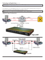
966R Rear Panel Connections
Alarm Relays
For connection to central office alarm systems. There are two alarm relays (A0 and A1). Each relay has a normally
open (NO) and a normally closed (NC) contact. To configure alarms connect a lead to the common (COM) terminal,
and a second lead to the desired (NO or NC) contact terminal.
966R Front Panel
Except for channel activity LEDs the 966R front panel does not have any controls.
Sage Instruments • 966R User Manual • Telnet Command Line Remote Access
A. Getting Started
B. Navigating the Console
C. Administering the Sage Device
D. Gathering Information for Conducting Tests
E. Managing Test Results
F. Conducting Tests
G. Starting and Stoping Tests
H. Help Documentation for each Command
A. Getting Started:
1. Log into the console using a telnet terminal window.
2. To get a list of all the commands, type ‘help’.
B. Navigating the Console:
Navigation Commands:
help
Allows all users to access help on the various built-in commands.
cd
Changes the current directory.
dir
Displays current directory contents.
exit
Exits the command interpreter and closes associated network resources
1. Type ‘dir’ to get a list of all the files and directories in the current directory.
2. To change directories, type ‘cd <name of directory>’. If you need to change to the parent directory, type ‘cd ..’
3. To exit the console, type ‘exit’ .
C. Administering the Sage 966R:
Administrative Commands:
user
Access user information.
useradd
Creates a new user. Admin only.
userdel
Deletes a user. Admin only.
warmstart
Reboots the controller.
version
Displays the command interpreter.
versionpasswd
Change the current user’s password.
kick
Terminate a user’s session. Admin only.
time
Displays or sets system time
date
Displays or sets system date
(continued on next page)
Sage Instruments • 966R User Manual • 10
Telnet Access
Administrating the Sage 966R (continued)
1. To get a list of the users currently logged in, type ‘user -a’
2. To get a list of all registered users, type ‘user -d’
3. To add a user, type ‘useradd <username> <password>’
4. To delete a user, type ‘userdel <username>’
5. To reboot the controller, type ‘warmstart’
6. To get the command interpreter version, type ‘version’
7. To change the current user’s password, type ‘passwd’
8. To terminate a user’s session (as Admin only), type ‘user -a’ to get
a list of users and their associated session ids.
Then, type ‘kick <user’s session id>’ to terminate the user’s session.
9. To display the time, type ‘time’. To change the time, type ‘time
<HH:MM:SS>’
10. To display the date, type ‘date’. To change the date, type ‘date
<MM/DD/YYYY>’
D. Gathering Information for Conducting
Tests:
Information Commands for Tests:
intfc
View interface status; configure interfaces.
unit
Display unit information, activate options.
These commands are used to facilitate running the tests.
In order to conduct any of the tests, you will need the information
about each interface. To get info about each interface, type ‘intfc’
You will see a list of numbered interfaces available. To get more
details about each interface, type ‘intfc <interface number>’
important information about interfaces:
On the 96X Family of products, a 96X Unit is composed of one or
more phyical ‘interfaces’. An interface could be a PCM span, an
ethernet port, or an analog jack. Each interface is composed of
one or more ‘resources’. For example, a T1 span has 24 resources
(channels, in this case), and an analog interface has only one
resource. The ethernet interface has a number of resources called
‘slots’ that allow for the definition of multiple, simultaneous tests
on a single interface. Tests are defined at the resource level; if
a resource doesn’t have a test defined, it is considered an ‘idle’
resource.
These ‘interface’ and ‘resource’ abstractions allow for uniform
command, control, and administration of completely different
physical media. In this case Ethernet, PCM, and Analog media can
all be manipulated via the same commands by specifying only the
interface #. Likewise, individual tests are referenced by indicating
the interface # and resource #. To allow the different interfaces to
be reconfigured with this command, the configuration process is
interactive (you will be prompted for appropriate input).
(continued on next page)
Sage Instruments • 966R User Manual • 11
Telnet Access (continued)
Administrating the Sage 966R (continued)
Important PCM Note: Note that there are two ‘flavors’ of PRI ISDN supported: the normal PRI_ISDN setting
and the PRI_ISDN/Dyn setting. The Dyn setting means ‘dynamic’ B-Channel selection for responders that define
their originating number. When in this dynamic mode, if a call comes in, the responder ‘originating’ numbers
are searched for a match to the incoming destination number. If a match is found, the responder is started on
the B-Channel of the incoming call. Otherwise a responder without a originating number is started, if found.
The upshot of all this is that in the dynamic ISDN mode, the resource numbers DO NOT directly correlate with
B-Channels; they are merely test slots as they are on the Ethernet interfaces. As a consequence, in this mode
outgoing calls will be put up on arbitrary B-Channels. Furthermore, no indication of the B-Channel in use is
available to the user.
Examples:
To show high level status of all interfaces installed in the unit, use: intfc
To show detailed status of a specific interface, say #2, use: intfc 2
To (re)configure, say interface #2, (as Admin or owner of all tests on the interface), use: intfc -c 2
E. Managing Test Results
Test Utility Commands are as follows, and are used to help manage
test results.
Test Utility Commands:
deltest
Delete the specified test.
del
Delete a file
report
Report the latest results for the specified test.
tests
View status of tests
type
Display a file.
remctrl
Switch Unit to UI ‘Remote Control’ mode.
F. Conducting Tests
G. Starting & Stoping Test
Test Commands:
Test Utility Commands:
digrecv
Digit Receiver Test
start
Start the specified test
digsend
Digit Sender Test
stop
Stop the specified test
echogen
Echo Generator Test
10xd
10x Director Test
echosnd
Echo Sounder Test
10xr
10x Responder Test
faxrx
FAX Receiver Test
faxtx
Fax Transmitter Test
inmd
INMD Test
moipd
MoIP Director Test
moipr
MoIP Responder Test
pvit
PVIT Test
smosd
SMOS Director Test
smosr
SMOS Responder Test
smtone
Send/Measure Tone Test
Now that you have gathered the interface
information, you may now conduct tests
effectively.
(continued on next page)
Sage Instruments • 966R User Manual • 12
Telnet Access (continued)
Administrating the Sage 966R (continued)
H. Help Documentation for Each Command
For more information on a specific command, type ‘help command-name’. The following is an alphabetical listing
of usage and notes for each command.
Log into the console using a telnet terminal window:
To get a list of all the commands, type ‘help’:
Command:
cd
Use
Changes the current directory.
Notes
Supports basic up/down navigation. Understands single ‘..’ or a directory *relative* to and ‘below’
the current directory.
Command:
date
Use
Displays or sets system date. [aDate]
Notes
With no arguments, the system date is returned. Admin may set the system date via the paramter. [aDate] (Optional) MM/DD/YYYY
Command:
del
Use
Delete a file.
Notes
Delete the specified file. Filenames must be characters without whitespace.
Command:
deltest
Use
Delete the specified test.
Notes
Delete the specified test. Must be test owner or Admin; test must be disabled.
Command:
digrecv
Use
Configure Digit Receiver Test
Notes
Create a Digit Receiver test that parses incoming digits.
(continued on next page)
Sage Instruments • 966R User Manual • 13
Telnet Access (continued)
Administrating the Sage 966R (continued)
Command:
digsend
Use
Configure Digit Sender Test.
Notes
Create a Digit Sender test (default: director) that sends digits once the call is up. Digit parameters
do not effect call setup digits, only digits sent after call is up.
Command:
dir
Use
Displays current directory contents.
Notes
Simple current directory listing.
Command:
echogen
Use
Configure Echo Generator Test.
Notes
Create a Echo Generator Test (default: responder).
Command:
exit
Use
Exits the command interpreter and closes associated network resources.
Notes
None.
Command:
faxrx
Use
Configure FAX Receiver Test.
Notes
Create a Fax Receiver test (default: responder).
Command:
faxtx
Use
Configure Fax Transmitter Test.
Notes
Create a Fax Transmitter Test (default: director).
Command:
help
Use
Allows all users to access help on the various built-in commands.
Notes
For more information on a specific command, type ‘help command-name’.
Command:
inmd
Use
Configure INMD Test.
Notes
Create an INMD (passive echo monitor) test. Requires Dual Monitor mode for T1/E1.
Command:
intfc
Use
View interface status; configure interfaces.
Notes
Allows all users to view high-level status information on all installed interfaces. Allows a user who
owns all the defined tests or ‘Admin’ to (re)configure interfaces.
Command:
kick
Use
Terminate a user’s session. Admin only.
Notes
Admin may use the ‘kick’ command to invalidate a stranded or unknown session. The session
will terminate when the user sends input over the network connection and is then notified of the
impending disconnect; the resources are then reclaimed. Requires the sessionId of the session in
question. See the ‘user -a’ command help for details on how to determine the sessionId of other
sessions.
(continued on next page)
Sage Instruments • 966R User Manual • 14
Telnet Access (continued)
Administrating the Sage 966R (continued)
Command:
moipd
Use
Configure MoIP Director Test.
Notes
Create a MoIP Director Test.
Command:
moipr
Use
Configure MoIP Responder Test.
Notes
Create a MoIP Responder Test.
Command:
passwd
Use
Change the current user’s password.
Notes
Admin only may change other user’s passwords.
Command:
pvit
Use
Configure PVIT Test.
Notes
Create a PVIT Test (default: director). Receiver always enabled, sender enabled if a level is specified.
Command:
remctrl
Use
Switch Unit to UI ‘Remote Control’ mode.
Notes
Switch control of the unit from multi-user command line mode to standalone UI remote control.
Reboots the controller (but not the interface boards), drops all tests and sessions in progress. This
unit is optioned to run in multi-user command line mode as well as single-user remote control via
the 960B user interface PC application. Executing this command will:
- Kill all network connections to the unit (including this one!!).
- Reconfigure the unit for single-user remote control.
- Restart the control SW; this will take 30 seconds or so.
The Remote Control UI application has provisions to return to the command-line mode, if desired.
Command:
report
Use
Report the latest results for the specified test.
Notes
Available to all users; test must be enabled.
Command:
smosd
Use
Configure SMOS Director Test.
Notes
Create a SMOS director test that calls a SMOS responder.
Command:
smosr
Use
Configure SMOS Responder Test.
Notes
Create a SMOS Responder test that waits for calls a SMOS Director.
Command:
smtone
Use
Configure Send/Measure Tone Test.
Notes
Create a Measure Tone test (default: director) that optionally sends a tone.
Command:
start
Use
Start the specified test.
Notes
Must be test owner or Admin; test must be disabled.
(continued on next page)
Sage Instruments • 966R User Manual • 15
Telnet Access (continued)
Administrating the Sage 966R (continued)
Command:
stop
Use
Stop the specified test.
Notes
Must be test owner or Admin; test must be enabled.
Command:
10xd
Use
Configure 10x Director Test.
Notes
Create a 100, 102, or 105 Director Test.
Command:
10xr
Use
Configure 10x Responder Test.
Notes
Create a 100, 102, 105 (default), or 108 Responder Test.
Command:
tests
Use
View test status of all tests or just specified interface.
Notes
Resources without defined tests are considered ‘idle’. Options allow for filtering results.
Command:
time
Use
Displays or sets system time.
Notes
With no arguments, the system time is returned. Admin may set the system time via the paramter.
(Optional) HH:MM:SS
Command:
type
Use
Display a file.
Notes
Displays the contents of the specified file.
Command:
version
Use
Displays the command interpreter version.
Notes
Validate that the Command Language version is correct as the first command after logging in.
Command:
unit
Use
Display unit information, activate options.
Notes
Lists detailed unit info. Admin rights req’d to rename the unit or activate new options.
Command:
user
Use
Access user information.
Notes
Lists the current logged-in user info. Admin rights req’d to view all defined users.
Command:
useradd
Use
Creates a new user. Admin only.
Notes
Creates a new user with the specified password and associated directory. Admin Only.
Command:
userdel
Use
Deletes a user. Admin only.
Notes
Deletes an existing user and associated directory. Admin only.
Command:
warmstart
Use
Reboot the controller.
Notes
Reboots the controller (but not the interface boards), dropping all tests and sessions in progress.
Sage Instruments • 966R User Manual • 16
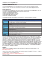
966R Technology and Applications
The 966R IP Telephony Multi-Channel Test instrument is specifically engineered to identify, measure and diagnose
all IP Voice processing Impairments. All elements that degrade voice services can be tested and identified with the
966R including:
• Excessive compression by low-bit vocoders
• Voice level too low/High
• Excessive packet/cell/frame loss/slip
• Excessive voice jitter (Jitter buffer resizing)
• Excessive voice clippings (VADs)
• Excessive noise (CNG) or not enough
• Excessive delay
• Echo
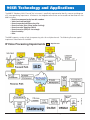
The 966R supports a variety of real-time processing tasks for multiple channels. The following illustrates typical
impairments identified with the 966R.
IP Voice Processing Impairments
= Impairments
Sage Instruments • 966R User Manual • 17
Technology and Applications (continued)
SMOS Director/SMOS Responder
Provides End-to-End Voice Quality Characterization. Tests the networks ability to transmit voice distortion free in
both directions through gateways, IADs and IP Phones.
Artificial Voice Test Signal (All Accents)
Metrics
Voice Clarity (MOS)
Listener Impact
Distortion, Packet Loss
Voice Packet/Frame Slips
Voice Gapping, Jerking
Round Trip Delay
Talk-over
Audio Level
Too Loud or Quiet
Comfort Noise
Too High or Too low
Effective Bandwidth
In-band data qualification
Codec Type Detection
Provisioned incorrectly
PVIT (Packet Voice Impairment Test)
Provides Comprehensive Voice Quality Performance Metrics. Enableing field personnel to zero in on causes of poor
voice quality. Considered the DS0 BERT test for VoIP.
Metrics
Voice Clarity (MOS)
Listener Impact
Distortion from Packet Loss
+/- Frame Slip Event Count
Voice Gapping and Jerking
Voice Clipping Event Count
Choppy Voice
Noise Hit Event Count
Impulse Noise During silence period
PVIT statistics provided for each event type:
• Average Burst Length (msec)
• Min/Max Burst length (msec)
• Percent of impairment over test duration (i.e. % packet loss)
FAX (Transmit and Receive)
During testing the SAGE 966R FAX emulators will report in real time the test progress, such as what signal is being
sent; what signal is being received; whether or not a certain stage is being retried; whether or not an unexpected
invalid protocol packet is received; whether or not timing errors have occurred, and whether or not the page
transmission has succeeded.
Metrics and Features
Emulate Up to 120 Facsimile Transmitters and Receivers
Stress Gateway for In-band Data Transparency
Terminate Fax on TDM, Packet, and Analog
Decode V.21 (FSK) Two-way Fax Transmission
Support Data Rates for V.17 and V.27
(continued on next page)
Sage Instruments • 966R User Manual • 18
Technology and Applications (continued)
MoIP (Modem over IP)
The 966R MoIP test objectively measures a packet networkís ability to carry telephony traffic including voice, data,
and fax. The test process emulates three modes of operation: Voice, Data, & Fax. MoIP sends appropriate priming
tones (i.e. CNG) to provoke tone detection for call type (Data Mode). MoIP tests also generate pseudo random test
signals to verify data mode transparency (essentially 64 KB/s). Fax & Data modems use vulnerable FSK signaling
(V.21).
MoIP Test
Metrics
Voice Audio Level, Frame Loss, Frame Jitter (+/-), Codec Type
and Round Trip Delay
Data
Frame Loss, Frame Jitter (+/-), Codec Type, and Round
Trip Delay
Fax
Frame Loss, Frame Jitter (+/-), Codec Type, and Round
Trip Delay
Digit Analyzer
Digit Tests
Function/Results
DTMF/MF Digit Verification
Next Gen Nets Encode & Decode Digits
On/Off Times, Frequency & Level
Detects ANSI Standards and RFC-2833 Digits
Digit Sender Envelope Testing
Settable Frequency and Level and On/Off times
Send RFC-2833 Digits
Echo Sounder/Echo Generator
Provides Echo Detection and Echo Canceller verification. Enables field personnel to detect and isolates echo
problems from a TDM, 10/100, or Analog interface.
• Echo Generator • Advanced Echo Emulation • Multi-channel to stress embedded echo cancellers
Metrics
Listener Impact
Echo Level(s)
Echo Loudness
Echo Delay(s)
As delay gets longer echo becomes more noticeable
Requirements Specified in ITU G.131
INMD (In-Service Non-intrusive Measurement Device) International Telecommunication Union-T P.561
INMD on the 966R platform focuses on echo characterization. More specifically, once the presence of echo is
detected, the 966R will report in real time the detected echo level and echo delay. A graphical snapshot of the
reference and echo signals is also displayed as further visual confirmation. If the monitored DS1 are PRI-ISDN lines,
then the source and destination phonenumbers associated with the monitored DS0 channel are also presented.
Function
ITU P.561 Non-Intrusive VQ Characterization
Passively Detects Echo in both directions via Dual Monitor E1/T1 or RTP Monitor
Monitor up to 60 TDM Channels Simultaneously and/or Up to 256 RTP Streams
Measures and Captures both Echo Level and Delay with Option to Record Audio
(continued on next page)
Sage Instruments • 966R User Manual • 19
Technology and Applications (continued)
INMD (In-Service Non-intrusive Measurement Device) (continued)
INMD P.561 Passive Echo Monitoring
To run INMD tests ,the SAGE 966R front panel PCM 1 and PCM2 connections need to be paired. Leaving PCM 3
and PCM 4 for connection to the reference signal (see figures 27 & 27a).
Note: For INMD, PCM 1 and PCM 3 must be connected to “Talker” reference signal.
INMD P.561 Typical Configurations
Sage Instruments • 966R User Manual • 20
Technology and Applications (continued)
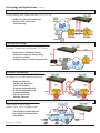
One-Way Delay Test
Use the 966R One-Way Delay test to measure one-way delay between disparate telephony interfaces in the lab.
• TDM to TDM
• IP to TDM
• TDM to Analog
• IP to Analog
Pinpoint delay issues to segments
of the network. Test works with
multiple 960 B’s as long as the
real-time audio ports (mic & spk)
are connected.
End-to-End Trunking Gateway
Gateway pass through transparency testing.
• Test Cancellers
• Verify In-band data or T.38 testing
• Voice Quality
• DTMF encoding/decoding (E911 testing)
Access Gateway
Access Gateway test configuration
• Turn-up, and Certification
Testing (SIP, RTP MON, TDM
Call)
• Voice Quality
• Echo
• Fax
IXC Long Distance Gateway
LD or Packet Tandem configuration (Class IV)
• Certification Testing
• Voice Clarity
• Delay
• Echo
• Data
• Fax
(continued on next page)
Sage Instruments • 966R User Manual • 21
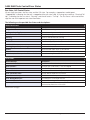
Technology and Applications (continued)
Echo Troubleshooting
Passively Monitor Echo, Audio Level and RTP (G.711/G.729)
• INMD ITU P.561 (Level and Delay)
• Monitor 100’s of channels
simultaneously
CPE/QA/Cert Testing
Functional Customer Premise Equipment (CPE) Testing
• Regression or parametric testing
• Functional testing for Clarity, Delay,
Echo, Fax and Data
• Multiple channels via FXO channel bank
Canceller Performance
Echo detection & canceller performance testing
• Complete Echo and
Double-Talk Emulation
(with ITU Standard
Dispersive Hybrid Models)
• G.168 Test Suite Manual or
Automated Modes
• Test Cancellers over
Multiple Channels
VoIP Pre-Qualification
Place multiple SIP calls to access
readiness (up to 128 in full duplex mode)
• Test Segments and Backplanes
• Emulate Real IP Phones with
Jitter Buffers
(continued on next page)
Sage Instruments • 966R User Manual • 22
Technology and Applications (continued)
SAGE Online Referrence Material
SMOS (Sage Mean Opinion Score) White Paper available via www.sageinst.com located at:
http://www.sageinst.com/downloads/900series/SMOS-Spec.pdf
Packet Voice Impairment Test White Paper available via www.sageinst.com located at:
http://www.sageinst.com/downloads/925/pvitwp1.pdf
Echo Sounder & Echo Generator White Paper available via www.sageinst.com located at:
http://www.sageinst.com/downloads/925/ecegwp1.pdf
New IP Telephony Transparency Test, MoIP, Fax, Data & Voice White Paper available via www.sageinst.com
located at:
http://www.sageinst.com/downloads/moip.pdf
Fax Emulator Test White Paper via www.sageinst.com located at:
http://www.sageinst.com/downloads/960A/faxtrx6_04.pdf
P.561 INMD Test White Paper available via www.sageinst.com located at:
http://www.sageinst.com/downloads/inmd.pdf
G.168 Test Suite White Paper available via www.sageinst.com located at:
http://www.sageinst.com/downloads/925/g168wp.pdf
Visit SAGE Instruments at www.sageinst.com
Sage Instruments • 966R User Manual • 23
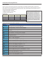
SAGE 966R Tests Control/Error States
Run State, Call Control Status
All tests have two states: the Run state, and the Call state. For example, a stopped test would report
“Stopped(Idle)” indicating that the test is stopped and the call state is idle. A running test would say “Running(Call
Up)”, indicating that the run state is “Running” and the call state is “Call Up”. The Test Status is also used to message the user with important test state information.
The following are the possible Run States and descriptions:
Normal Run States:
Status Message
Description
Stopped
The test is not running
Cycling or Recycling Test
The test is starting or restarting
Pause or Pause with duration
The test is pausing prior to start (allows responders to recycle)
Running
The test is considered to be running
Stopping
The test is stopping (call is being torn down, etc.)
Make Call
The call is being set up for the test
Wait for Call
A responder is waiting for a call
Running/Responder (or Running)
Run state for Responder
Hybrid
Echo Generator under active G.168 Control
Manual Dial...
The user is manually sending digits
Load aLaw, Load uLaw, or Load Wav and % done
The test is sending the associated PCM file to the DSP
Error States:
Status Message
Description
Error: DSP Error State
Certain tests indicate that they are in Error and need to be restarted
Span In Alarm...
The PCM span is not healthy. Tests are stopped
Can’t Connect
The call failed; the test never started
Channel Blocked
The requested channel is no longer available
Error: Test won’t start!
The DSP did not report the test started
Error: Test won’t stop!
The DSP continues to report the test running in Stopped state
Error: Wrong DSP Test!?
The wrong test is running on the DSP
Error: DSP Test Died!
The test was running, but it suddenly stopped
Too many SMOS Tests!
The User attempted to run too many SMOS tests, so some were
terminated to protect the PCM stream
(continued on next page)
Sage Instruments • 966R User Manual • 24
SAGE 966R Tests Control/Error States (continued)
Call Control Normal States:
Status Message
Description
Acquire Channel
ISDN, Making Call -- Acquire necessary resources for call
Acquire Digits
The far end is expected to send digits, near end waits for them.
Acquire Dial Tone
Waiting for dial tone
Connect
Call up state for FXS/FXO calls
Call Up
Call up state
Dial, Dial Digits
Dialing digits
Dial Tone
Same as Acquire Dial Tone
Hook Off
Command near hook off
Hook On
Near hook is commanded on prior to going off hook, in case it wasn’t on to begin with
Hook On(1s)
Wait for 1 second in the hook on state to avoid false signaling transients
Idle
No call is up; no intent to put one up
Initiate(0)”, etc.
Initiate States indicate the beginning of a particular call sequence
Loop Closure?
FXO, Ground-start, NT, Making Call -- waiting for far end to answer
Measure Wink
Measure a wink sent by far end
Near Hook Off
Near hook commanded OFF
Near Hook On(180), etc.
Command near hook ON
Ring?
FXO, Loop start, NT, Making Call -- Sending ringing signal, waiting for FXS to answer
Ring Down
FXS/FXO, wait for “Ringing” to go away after ‘Tripping the Ring’ (answering the call)
Ring Ground?
FXO, Ground-start, NT, Making Call -- waiting for ‘ring ground’ from FXS (far) side
Send Dial Tone
NT, issue dial tone to far end
Setup Call
ISDN, Making Call -- Issue actual ISDN Call Setup message
Tip Ground?
FXS, Ground-Start, Waiting for ‘Tip-Grounding’ from FXO side
Wait Connect
Call setup is done on our side, wait for far end to finalize
Wait 4 Call
PRI ISDN, TE, Answer Call -- waiting for call setup message
Wait 4 Hook Off
Near is answering a call, waiting for far hook off, which means a call is incoming (if wink start,
set near hook off to start a wink)
Wait 4 Hook On
Near is answering a call, first make sure far hook is ON
Wait for Ring, Wait Ring
FXS/FXO Answer call, waiting for incoming ‘ringing’ state
Wait Tip-Ground
FXS, Ground-start, TE, Answer Call -- Need to see Tip-ground state before proceeding
Wait for Wink
Wait for the far end to send a wink to the near end
Wink Off
Command near hook off as part of a wink
Wink”, “Wink On
Command near hook on as part of a wink
Call Control Error States:
Far-End Busy
User Aborted
No Wink
Wink too Long
Far End Abort
No Answer
PCM/Frame Loss
No Dial Tone
Sage Instruments • 966R User Manual • 25
,
Configuring and running 966R Tests
Send/Measure Tone Test
Sage’s Send/Measure Tone is a test feature that enables sending and receiving a user specified tone. Send/Measure
tone is useful in measuring the difference in level from sending to receiving end-to-end points. The tone level can
be observed via the spectrum analyzer.
Specifications
Tone Test Transmit
Composite Level: -40 to 0 dBm
Individual Tones: Level: -13.6 dB below composite level
Flatness: ±0.2 dB
Frequencies: 203.125-3640.625 Hz in 156.25 Hz steps, ±10 ppm
Phase per IEEE 743 ±0.25∞
Peak to RMS Ratio 8.79
Tone Test Receive
Range:-40 dBm to -6 dBm
Accuracy: ±0.2 dB
Note: All command line entries are typed
as characters without whitespace.
Note: When inserting a WAV file, the
maximum file length should be no more
than 256K samples or approximately 32
seconds of raw PCM (a-Law or μ-Law), 8
Khz encoding at 8, 16, or 32 bits.
Create a Send/Measure Tone tesst
Command:
smtone
Parameters
smtone [-dn] [-sn] -if [-rn] [-log] [-dir] [-resp] [-mf] [-dur] [Tx Freq] [Tx Level]
-dn
destination(Optional)
-sn
source #(Optional)
-if
IF# 1 to 6
-m
Resource#(Optional) 1 to 255
-log
Log File(Optional)
-dir
Be Director: # times to run {0}(Optional) 0 to 999
-resp
Be Responder(Optional)
-mf
Send MF call setup digits (CAS only) {DTMF}(Optional)
-dur
Test Duration(s) {0}(Optional) 0 to 86400
Tx Freq
[Tx Freq] (Optional) 20 to 3980
Tx Level
[Tx Level] (Optional) -60 to 3
Examples:
Create a smtone responder on interface #2, resource #3 that answers a call, sends a tone at 1004Hz at -12 dBm
until the far end hangs up. smtone -if 2 -rn 3 -resp 1004 -12
Create a smtone responder on interface #2, resource #3 that answers a call, sends a tone at 1004Hz at -12 dBm
for 20 seconds and then hangs up. smtone -if 2 -rn 3 -resp -dur 20 1004 -12
Create a smtone director on the first available resource of interface #1 that calls ‘831-761-1000’, sends tone for 12
seconds at 440Hz, -3 dBm and logs any measured (returned) tone to mtone.log.
smtone -if 1 -dn 8317611000 -dur 12 -log mtone.log 440 -3
Create a smtone director on the first available resource of interface #1 that calls ‘831-761-1000’ and logs any
measured tone to mtone.log for 12 seconds. No tone sent.
smtone -if 1 -dn 8317611000 -dur 12 -log mtone.log
Sage Instruments • 966R User Manual • 26
Configuring and Running 966R Tests
SMOS Director Test
Purpose and Function
The Sage Instruments Mean Opinion Score (SMOS) test provides an accurate assessment of how telephone users
perceive speech quality over a live VoIP network. SMOS provides a comprehensive set of measurements that
pertain to all aspects of voice quality. The SMOS test uses a robust algorithm to deliver accurate results in the
presence of jitters, band limitations, and dropouts, producing both near-to-far and far-to-near measurements.
SMOS Measurements
• Clarity - Mean Opinion Score (MOS)
• Effective Bandwidth - % available in the 300 Hz to 3400 Hz range
• Voice Frame Slips - compressive and expansive jitters in milliseconds
• Comfort Noise Level - measured in dBrnC during silent period
• Gain - audio level change measured in dB
• Codec Type - detects and reports codec type used
• Delay - round trip measured in milliseconds
• Call Completion Time - completion time measured in seconds
Create an SMOS director test
Command:
smosd
Parameters
smosd [-dn] [-sn] -if [-rn] [-log] [-dir] [-resp] [-mf] [Duration (sec) {9}]
-dn
destination(Optional) Characters without whitespace
-sn
source #(Optional) Characters without whitespace
-if
IF# 1 to 6
-m
Resource#(Optional) 1 to 255
-log
Log File(Optional) Characters without whitespace
-dir
Be Director: # times to run {0}(Optional) 0 to 999
-resp
Be Responder(Optional)
-mf
Send MF call setup digits (CAS only) {DTMF}(Optional)
-dur
[Duration (sec) {9}] (Optional) 0 to 255
SMOS stands for Sage (Instruments) Mean Opinion Score. SMOS provides an automated, fast, convenient and
accurate end-to-end assessment of voice quality for any VoX applications. SMOS follows the automated responder
test format and employs robust in-band telemetry and synchronization withtrue real-time processing. The test
can be conveniently used in both laboratory environments as well as across a real telephone network. SMOS was
developed largely out of Sage’s prior experience with PSQM and PVIT. SMOS provides an accurate MOS score that
truly matches human perception even in a live VoP network where certain impairments such as voice jitters (sudden
delay variations or frame slips) and attenuation distortion may render other voice quality tests such as PSQM
inapplicable. SMOS contains a reliable Bark-domain partial equalization along with asymmetric masking to properly
account for attenuation distortion, and a robust de-jittering algorithm to remove and simultaneously measure any
voice jitters (sudden delay variations). The psychoacoustic core is based on the work of Wang et al, Zwicker et al
and Sage’s own internal research. Besides the MOS number, SMOS also provides a set of other
‘orthogonal’ measurements that are vitally important in determining the overall voice quality of a network, or
trouble-shooting the configuration and traffic engineering of a problematic network. These measurements are
orthogonal to MOS because they are not properly reflected in the MOS number, yet they are also important
indicators of the overall QoS of the network.
Other measurements are round-trip delay, codec type, effective bandwidth, voice-band gain, silence noise level,
(continued on next page)
Sage Instruments • 966R User Manual • 27
Configuring and Running 966R Tests
SMOS Director Test (continued)
SMOS Tests
Range
Director or Responder
1 to 12 SMOS director/responder tests can be RUN
simultaneously on a single TDM interface.
Specifications
SMOS Signal
Artificial Voice
per ITU-T P.50
Active Speech Level
-20 dBTLP
SMOS
Measurement
Range
Accuracy
MOS
1.00 to 5.00
+/- .05
Noise
0 to 90 dBrnC
+/- 1 dB
Frame Slips
0 to 2000 msecs
+/- 1 msec
Effective Bandwidth
0.0 to 99.9%
+/- .2%
Gain
-80 to +20 dB
+/- 1 dB
Delay
0.0 to 5000.0 msec
+/- .2 msec
Codec
See “Codec Types
tolerates up to
Detected”
15% packet loss
Codec Types Detected
SMOS Test Result
Codec Type Description
VCD4K
Sub-4kbs vocoders
VCD8K
5-8kbps vocoders
VCD16K
12-16kbps vocoders
ADPCM16
16kbps G.726 ADPCM
ADPCM24
24kbps G.726 ADPCM
ADPCM32
32kbps G.726 ADPCM
ADPCM40
40kbps G.726 ADPCM
ADPCM
G.726 ADPCM with unknown
data rates
PCM
G.711 µ/A-law PCM or pure
analog
UNSURE
Distortion prevents codec type
detection
SMOS Test
Parameters
Range
Default
Test Duration
3 to 60 seconds
10 seconds
Send TLP
-30.0 to +10.0 dBm
0.0 dBm
Receive TLP
-30.0 to +10.0 dBm
0.0 dBm
total amount of compressive jitters (positive
frame slips or shortening of delays) and the
total amount of expansive jitters/frame slips
(lengthening of delays).
SMOS measures an objective MeanOpinion-Score between 1 and 5. 5 means
perfect and 1 means the worst. For all
practical measurements, the upper limit of
MOS will be between 4.5 and 4.6.
A MOS number between 3.0 to 4.0 is
considered to be communication quality
(intelligible but unnatural, or could be
annoying and lack of speaker
recognition etc). A MOS number below 3.0
is unacceptable for voice
communication. In a typical VoP (Voiceover-Packet) network, the measured MOS
number largely reflects speech degradation
caused by the following likely
impairments:
1. Lossy voice coder compression.
2. Packet loss and voice clipping.
3. Voice jitters in active voice period.
4. Interference signal and noise.
5. Excessive attenuation distortion.
Example:
Create a smosd test director that runs 10
times on interface 4 resource 14,calls 234234-8873, and logs the results to smos.csv:
smosd -dir 10 -if 4 -rn 14 -dn
2342348873 -log smos.csv
Sage Instruments • 966R User Manual • 28
Configuring and Running 966R Tests
SMOS Responder
Purpose and Function
The Sage Instruments Mean Opinion Score (SMOS) test provides an accurate assessment of how telephone users
perceive speech quality over a live VoP network. SMOS provides a comprehensive set of measurements that pertain
to all aspects of voice quality. The SMOS test uses a robust algorithm to deliver accurate results in the presence of
jitters, band limitations, and dropouts, producing both near-to-far and far-to-near measurements.
Create a SMOS Responder test that waits for calls a SMOS Director.
Command:
smosr
Parameters
smosr [-dn] [-sn] -if [-rn] [-log] [-dir] [-resp] [-mf]
-dn
destination(Optional) Characters without whitespace
-sn
source #(Optional) Characters without whitespace
-if
IF# 1 to 6
-m
Resource#(Optional) 1 to 255
-log
Log File(Optional) Characters without whitespace
-dir
Be Director: # times to run {0}(Optional) 0 to 999
-resp
Be Responder(Optional)
-mf
Send MF call setup digits (CAS only) {DTMF}(Optional)
Note: After Configuration is complete enter the command [start] . To view results of the SMOS Responder
test configure the same channel on a different PCM for a SMOS Director test. See director side for
results.
Example:
Create a SMOS responder that answers incoming calls on interface #1 resources 1-5:
smosr -if 1 -rn 1-5
Sage Instruments • 966R User Manual • 29
Configuring and Running 966R Tests
Packet Voice Impairment Test (PVIT)
PVIT provides detailed diagnostic information about events that impact voice clarity over packet switched
networks, including: voice frame losses, voice frame slips (also know as jitters), voice clippings and noise hits
Purpose and Function
PVIT works by sending a complex test signal over the network, and measuring events that degrade that signal. The
PVIT signal is a carrier-modulated spread spectrum signal with silence insertion.
• Measures four types of impairment events
• Displays cumulative event counts in real time
• Displays details about events as they occur
• Accumulates data over the test period
Test Duration 15 minutes, 1 hour, 24 hours, or continuous (NOTE: The continuous up to 1000 hours)
Command:
pvit
Parameters
pvit [-dn] [-sn] -if [-rn] [-log] [-dir] [-resp] [-mf] [-dur] [-mask] [Tx Level (dBM)]
-dn
destination(Optional) Characters without whitespace
-sn
source #(Optional) Characters without whitespace
-if
IF# 1 to 6
-m
Resource#(Optional) 1 to 255
-log
Log File(Optional) Characters without whitespace
-dir
Be Director: # times to run {0}(Optional) 0 to 999
-resp
Be Responder(Optional)
-mf
Send MF call setup digits (CAS only) {DTMF}(Optional)
-dur
Test Duration (s) {0}(Optional) 0 to 1000
-mask
[-mask] Mask (ms) {0}(Optional) 0 to 1000
Tx Level
[Tx Level (dBM)] (Optional) -20 to 0
PVIT stands for Packet-Voice-Impairments-Test or Packet-Voice-Integrity-Test. It is one of a series of VQT (VoiceQuality-Test) tests designed by Sage to specifically address the next generation VoP (Voice-over-Packet) applications.
Other related VQT tests available from Sage are SMOS and Echo Sounder. PVIT measures such packet network
impairments as packet loss, voice clipping, jitter and comfort noise level. Unlike other impairments such as delay,
echoes and lossy voice compression/transcoding which are static in nature and are not necessarily unique to VoP
(PSTN also has these problems), the packet loss, voice clipping and jitter type of impairments are unique to VoP and
are dynamic in nature. By using PVIT to objectively monitor these dynamic impairments at a regular basis, one can
assure the consistence of QoS (Quality-of-Service). For meaningful PVIT results, the reciever must detect a valid PVIT
signal. This can be from another PVIT transmitter or it’s own signal looped back. The transmitter is off by default
but is enabled when a send level is specified.
Examples:
Create a PVIT test responder that sends at -10dBm (and receives) the signal on interface #2 resources 11-18:
pvit -resp -if 2 -rn 11-18 -10
Create a PVIT test director that calls 782-9293 using interface #3 resource #13,sends the PVIT signal at -12 dBm for
15 seconds and logs to pvit.csv. Repeats 5 times.
pvit -dir 5 -dur 15 -if 3 -rn 13 -dn 7829293 -log pvit.csv -12
(continued on next page)
Sage Instruments • 966R User Manual • 30
Packet Voice Impairment Test (PVIT) (continued)
PVIT Test Real Time Metrics
Totals and Events Tabs
The Totals tab displays a group of metrics that are near-end metrics
of count average and percentage captured during measurement.
The Events tab displays near-end results showing individual impairment events. Users have the ability to toggle between totals and
events by clicking on the tabs (see figure 68).
The results for metric Totals are displayed in a table of 8 rows and
4 columns In the first row are two fields, one for “Send Level”
or Transmit level and “Elapsed Time” (see example below) the
remaining rows display test data. The cells 0 or 0.00 depicted in grey
are buttons that not only display data, but when clicked control the
graphic representation of that buttons data message (see close-up
figure 69).
Send Level:
Elapsed Time:
Counts
Avg.
%
Frame Loss:
0
0.00
0.00
+Frame Slips:
0
0.00
0.00
-Frame Slips:
0
0.00
0.00
Net Slips:
0
0.00
0.00
Noise Hits:
0
0
Voice Clips:
0
0.00
Frame Loss: Packet/Frame Loss Includes total elapsed test time, net
total PL/FL impairment time, PL/FL event count, PL/FL Average and
PL/FL % of total time.
Positive Packet/Frame Slips: A measure of voice signal compression (jerking). Includes total elapsed test time, net total +PS
impairment time, +PS event count, +PS/FS Average and +PS% of
total time.
Specifications
PVIT Measurement Precision
• Voice Frame Loss: ±2 ms
• Voice Frame Slip (jitter): ±0.5 ms
• Voice Clipping: ±2 ms
• Noise Level: ±1 dB
• Percentage Voice Frame Loss: ±10% of
actual % of frame loss
The results for Events are reported as
recorded events. Results include event
type, event duration, and time stamp.
Event types can be:
• IS: In_SYNC
• RS: SYNC Recovered
• SL: Signal Lost, SYNC Lost
• SR: Signal Recovered
• PL: Packet/Frame Loss
• PS: Packet/Frame Slip (Delay Variation)
• VC: Voice Clip
• NH: Noise Hit
• DC: Detection of Clock Drift
Negative Packet/Frame Slips: A measure of voice signal expansion
(gapping). Includes total elapsed test time, net total -PS impairment
time, -PS event count, -PS/FS Average and -PS% of total time.
Net Slips: Net slip counts, average and %.
Noise Hits: Transient Impulse Noise; Includes total elapsed test time,
noise event count, and average event duration.
Voice Clippings: Includes total elapsed test time, net total VC
impairment time, VC event count, and average event duration.
Sage Instruments • 966R User Manual • 31
Configuring and Running 966R Tests
Echo Sounder
Purpose and Function
Echo is one of the most important quality of service factors in a
telephone network. Sage Instruments echo test suite includes a complete set of tools to characterize the level
and delay of echoes on a network. It provides an objective measurement of this important aspect of overall voice
quality.
Specifications
The Sage Echo Sounder test measures echoes with the following:
• Echo levels and Echo delays
• Round trip delay and Round trip attenuation
• One way delay and One way attenuation
The measurement ranges and precisions of Echo Sounder are shown in the table below. The echo delay ranges
differ slightly with different interfaces.
Connection Interface
Echo Level Range/
Precision
Echo Delay Range/
Precision
2-Wire Analog
[-60,20]±1 dB
[7,900]±1ms
4-Wire Analog
[-60,20]±1 dB
[0,900]±1ms
T1/E1
[-60,20]±1 dB
[0,900]±1ms
Create an Echo Sounder Test (default: director).
Command:
echosnd
Parameters
echosnd [-dn] [-sn] -if [-rn] [-log] [-dir] [-resp] [-mf] [-ecd] [-ecf] [-ecl] [-ecmf] [-ecmi] [-ecnc] [ecpd] [-ecpj] [-silence] [-cycles] [Tx Level (dBM) {-10}]
-dn
destination(Optional) Characters without whitespace
-sn
source #(Optional) Characters without whitespace
-if
IF# 1 to 6
-m
Resource#(Optional) 1 to 255
-log
Log File(Optional) Characters without whitespace
-dir
Be Director: # times to run {0}(Optional) 0 to 999
-resp
Be Responder(Optional)
-mf
Send MF call setup digits (CAS only) {DTMF}(Optional)
-ecd
Enable EC Disable Tone(Optional)
-ecf
EC Disable Freq (Hz) {2100}(Optional) 20.00 to 3980.00
-ed
EC Disable Level (dBm) {-12}(Optional) -20.00 to 0.00
-ecmf
EC Disable Mod Freq (Hz) {15.0}(Optional) 0.00 to 500.00
-ecmil
EC Disable Mod Index {0.2}(Optional) 0.00 to 1.00
-ecnc
EC Disable # Cycles {3}(Optional) 1 to 10
-ecpd
EC Disable Phase Duraton (ms) {450}(Optional) 10 to 1000
-ecpj
EC Disable Phase Jump (Deg) {180}(Optional) 0.00 to 180.00
-silence
Silence Duration (sec) {3}(Optional) 0.00 to 180.00
-cycles
Number of Test Cycles {3}(Optional) 0.00 to 180.00
Tx Level
[Tx Level (dBM) {-10}] (Optional) -20.00 to 0.00
(continued on next page)
Sage Instruments • 966R User Manual • 32
Configuring and Running 966R Tests
Echo Sounder (continued)
Discussion:
The Sage Echo Sounder test sends a proprietary test signal to characterize echos that may be present on the line
under test. It is capable of sending an initial echo canceller disable tone prior to the test signal. Default: no
disable signal. The parameters of the disable tone are customizable. The Silence duration determines the leading
and inter-test (if num cylcles > 1) silence in seconds. A larger leading silence may be useful if calling a line that is
slow to answer. The number of cycles is used to repeat the echo sounder tests multiple times during a single call
to look for dynamic changes.
Examples:
Perform a echo sounder test on interface #3 resource #2 using the default values (Tx Level = -10, no EC Disable
tone) to destination #434-8794:
echosnd -if 3 -rn 2 -dn 4348794
Perform a echo sounder test on interface #3 resource #2 using the default values (Tx Level = -10, no EC Disable
tone) to destination #434-8794 and send the echo canceller disable signal:
echosnd -if 3 -rn 2 -dn 4348794 -ecd
Sage Instruments • 966R User Manual • 33
Configuring and Running 966R Tests
Echo Generator
Sage Instruments Echo Generator generates multiple echoes with programmable echo delay and echo level.
When combined with Echo Sounder, Echo Generator facilitates the G.168-type [1] of echo canceller test and the
measurements of round-trip delay and round-trip attenuation. When working alone, Echo Generator serves as a
simple remotely-programmable loop-back.
• Programmable echoes and levels
Note: For Analog 2-wire, EGEN requires
• Global echo disable in manual mode
an allotment of time to allow for 2-wire
• Facilitates echo canceller tests
interface calibration (~ 6 seconds). So
Specifications
when performing an echo sounder test
Circuit Type
Level Range/
Delay Range/
Frequency Range
to an echo gene on a 2-wire circuit, the
Accuracy
Accuracy
lead delay time on the echo sounder must
allow for calibration. If lead delay is not
Analog 2-wire
[-40,9]±0.5 dB
[17,600]±0.5 ms
300 to 3300 Hz
long enough, echo gen will not complete
Analog 4-wire
[-60,9]±0.2 dB
[17,600]±0.5 ms
300 to 3300 Hz
its calibration cycle and echo emulation
Digital T1/E1
[-60,9]±0.2 dB
[12,600]±1 ms
20 to 3900 Hz
will malfunction thus reporting incorrect
Note: As a Responder the Load type configuration is inactive.
results.
Create a Echo Generator Test (default: responder).
Command:
echogen
Parameters
echogen [-dn] [-sn] -if [-rn] [-log] [-dir] [-resp] [-mf] [-lvl1] [-dly1] [-lvl2] [-dly2] [-g168] [-gsm]
[-loop] [-pkt] [-jit] [-tone] [-hoth] [-dbl] [-bias]
-dn
destination(Optional) Characters without whitespace
-sn
source #(Optional) Characters without whitespace
-if
IF# 1 to 6
-m
Resource#(Optional) 1 to 255
-log
Log File(Optional) Characters without whitespace
-dir
Be Director: # times to run {0}(Optional) 0 to 999
-resp
Be Responder(Optional)
-mf
Send MF call setup digits (CAS only) {DTMF}(Optional)
-ecd
Enable EC Disable Tone(Optional)
-lvl1
1st Echo Level (dBm) {-10}(Optional) -50 to 5
-dly1
1st Echo Delay (ms) {100}(Optional) 24 to 500
-lvl2
2nd Echo Level (dBm) {no 2nd echo}(Optional) -50 to 5
-dly2
2nd Echo Delay (ms) {no 2nd echo}(Optional) 24 to 500
-g168
Dispersion=G168 Model# {none}(Optional) 1 to 8
-gsm
Dispersion Model=GSMFR {none}(Optional)
-loop
Dispersion Model=Loopback {none}(Optional)
-pkt
Dispersion Model=Packet Loss (%) {none}(Optional) 1 to 90
-jit
Dispersion Model=Packet Jitter (ms) {none}(Optional) 1 to 1000
-tone
Dispersion Scale Type {css}(Optional)
-hoth
Sig Gen=Hoth {none}(Optional) -100 to 0
-dbl
Sig Gen=CSS DblTalk {none}(Optional) -100 to 0
-bias
Sig Gen=DC Bias {none}(Optional) -100 to 0
(continued on next page)
Sage Instruments • 966R User Manual • 34
Configuring and Running 966R Tests, Echo Generator Test
(continued)
Discussion:
The default is a single echo of -10 dB at 100ms with no dispersion. For details on the G.168 dispersion models,
dispersion scale type, Hoth noise, or CSS Double-Talk see the ITU G.168 document, and/or the ‘G.168 White Paper’
available at www.sageinst.com The ‘gsm’ dispersion model is a GSM Full-Rate vocoder. The ‘packet loss’ and
‘packet jitter’ are useful for simulating/adding known impairments in a circuit. The ‘loopback’ is a true digital
loopback with no level adjustment, but with a delay specified by the first echo.
Examples:
Create an echo generator responder test with a single echo of -12 dB at 53 ms on interface #1 resource #3:
echogen -if1 -rn3 -lvl1 -12 -dly1 53
Create an echo generator responder test with a single default echo on interface 4 resource 5: echogen -if 4 -rn 5
Setting Echo Dispersion using G.168 Models
The following G.168 echo path models are used with the SAGE 966R Echo Generator test. The echo path is
simulated by a linear digital filter with the scaling factor Ki as referenced in the table below. The eight G.168
models represent echo paths with various dispersion characteristics and different time widths. For tests that use
CCS (Composit Source Signal) or white noise as the scaling factor the values of Ki are provided in the table below.
-–ERL / 20
g(k) = (10
Ki )mi (k-§)
* A minimum ERL value of 6 db should
Echo Path Model
Scaling Factor Ki
Minimum ERL for
be used in the tests for echo path models
CCS (dB)*
1, 3, 4. 5 and 6. For echo path models 2,
1
1.39 x 10⁻⁵
6
7 and 8 the minimum ERL values used in
2
1.44 x 10⁻⁵
6.55
the tests should be, respectively, 6.55 db,
3
1.52 x 10⁻⁵
6
11.06 db and 9.27 db. This ensures that
4
1.77 x 10⁻⁵
6
the magnitude response of the scaled
-6
echo-path g(k) does not exceed 0 db over
5
9.33 x 10
6
the appropriate frequency range.
-5
6
1.51x 10
6
7
8
2.33 x 10⁻⁵
1.33 x 10⁻⁵
11.06
9.27
For tests that use Tones as the scaling factor the values of Ki are
provided in the table below.
Echo Path Model
1
2
3
4
5
6
7
8
Scaling Factor Ki
Minimum ERL for
Tones (dB)*
1.22 x 10⁻⁵
6.78 x 10⁻⁶
6
9.66 x 10⁻⁶
1.07 x 10⁻⁵
6
7.05 x 10⁻⁶
8.60x 10⁻⁶
6
6.58 x 10⁻⁶
4.58 x 10⁻⁶
6
* A minimum ERL value of 6 db should be
used in the tests for all 8 echo path models. Each scaling factor is used to limit the
maximum of the magnitude response to
the chosen ERL value.
6
6
6
6
Single-talk CSS: Composite-Source-Signal. This is the signal used in most of the tests for G.168. In time-domain,
it consists of 3 portions, the active voice portion, the random noise portion and the silence (pause)p ortion. The
exact duration,power-spectral-density and peak-to-RMS ratio characteristics are specified in ANNEX C of G.168
See also the “Echo Sounder & Echo Generator” White Papers available via www.sageinst.com
Sage Instruments • 966R User Manual • 35
Configuring and Running 966R Tests
INMD P.561
Specifications
Interface
Range
Accuracy
TDM
0 to 511 ms
±one frame of uncertainty
INMD stands for In-service Non-intrusive Measurement Device. It is a passive voice quality monitoring method
based on ITU-T P.56. Two types of measurements are covered by INMD: 1, speech and noise characterization;
2, echo characterization. Sage’s current implementation of INMD on the 966R platform focuses only on echo
characterization. More specifically, once the presence of echo is detected, Sage’s INMD in the 966R will report in
real time the detected echo level and echo delay. A graphical snapshot of the reference and echo signals is also
displayed on the main test window as further visual confirmation. If the monitored DS1 are PRI-ISDN lines, then
the source and destination phone numbers associated with the monitored DS0 channel are also presented. Simply
speaking, INMD detects echo by principle of cross-correlation. More specifically, as implemented in the SAGE
966R, INMD has an internal signal analyzing window of 256ms long (2048 samples at 8000Hz sampling rate). For
detailed INMD P.561 network connection and operation principles see the link “Information in SAGE’s P.561 INMD
Test” found at www.sageinst.com/960_B_Tech.html.
Create an INMD (passive echo monitor) test. Requires Dual Monitor mode forT1/E1.
Command:
inmd
Parameters
inmd [-dn] [-sn] -if [-rn] [-log] [-dir] [-resp] [-mf]
-dn
destination(Optional) Characters without whitespace
-sn
source #(Optional) Characters without whitespace
-if
IF# 1 to 6
-m
Resource#(Optional) 1 to 255
-log
Log File(Optional) Characters without whitespace
-dir
Be Director: # times to run {0}(Optional) 0 to 999
-resp
Be Responder(Optional)
-mf
Send MF call setup digits (CAS only) {DTMF}(Optional)
Example:
Create inmd tests on interface #1 resources #1-23 and log the results to inmd.log (assumes the interface is
configured for Dual-Monitor Mode):
INMD P.561 Test Configuration
When using INMD, a user should connect
Sage’s 960 to the network as shown.
(continued on next page)
Sage Instruments • 966R User Manual • 36
Configuring and Running 966R Tests
INMD P.561 (continued)
The 966R has four DS1 (T1/E1/ISDN) spans, numbered as 1, 2, 3 and 4 with Rx and Tx ports (Use only the Rx ports
to make the connections). Internally, 1 and 2 are a pair controlled by one embedded processor, whereas 3 and 4
are another pair controlled by another embedded processor.
Since INMD entails precise relative delay measurement between two input signals, Sage’s 966R must be configured
in the following ways:
1. Two DS1 spans are used for INMD, although only the receiving ports need to be connected. The two DS1 spans
must be either the 1 and 2 pair, or the 3 and 4 pair. Other combinations such as 1 and 4 or 2 and 3 etc are not
allowed.
2. The chosen DS1 pair must be configured to “DUAL MONITOR” mode. When performing span configuration
through 966R’s GUI, one only needs to (and must) configure the first span (1 or 3) of each DS1 pair. The partner
DS1 span (2 or 4) will be configured automatically for you. A user configuration on the second DS1 span (2
or 4) has no effect. In “DUAL MONITOR” mode, the internal software will always set the DS1 clock source to
“EXTERNAL” clock regardless what the user selects on the GUI.
3. If the DS1 lines being monitored are PRI-ISDN lines, then the D-channel must be specified correctly when
performing the span configuration in order for INMD to intercept the source and destination phone numbers
associated with the DS0 channel(s) being monitored. If one is also interested in decoding all the ISDN call
messages, one should also specify the TE and NT modes correctly. As in “TERMINATE” mode, the 966R DS1 span
should be set to match the incoming NT or TE mode. For example, as illustrated if the signal goes into the receiving
port of 1 is from the NT equipment, then 966R’s PCM1 must be set to TE mode. Internally, 2 will automatically be
set to NT mode to match the signal from the TE equipment.
Sage Instruments • 966R User Manual • 37
Configuring and Running 966R Tests
MoIP Director
Purpose and Function
MoIP stands for Modem over IP. Sage Instruments designed this IP Telephony Service Transparency and E-model
Test to specifically verify a gateway or IADís ability to handle a MoIP call or a VoIP call. More specifically, the test
sends standard-based precursor signature tones by emulating a FAX call, a V34/V90 modem call or a voice call to
test the gateway’s call discrimination capability. After the signature
tones, the test then measures the round-trip delay as the delay is a good indicator of the internal jitter buffer size.
The test then starts simplex, full-duplex or half-duplex packet network impairments test by measuring in detail
each individual packet loss event and its duration, and each individual voice jitter (gapping or jerking) event and
its duration. The signal level change (gain) is also measured, and the codec type (PCM, ADPCM or VOCODER)
is also detected. When voice test mode is chosen, echoes (in terms of levels and delays) are also measured from
both directions using Sageís proprietary Echo Sounder algorithm. All of the measured parameters (round-trip
delay, vocoder type, packet losses and echoes) are then used as inputs into the ITU-T G.107 E-model to produce
a transmission rating factor R value, and the derivative GoB (Good or Better), PoW(Poor or Worse) and E-MOS
(E-model-based mean-opinion- score) numbers. With this test, a user can quickly determine whether or not the
device and network under test can handle various MoIP or VoIP calls.
Create a MoIP Director Test.
Command:
moipd
Parameters
moipd [-dn] [-sn] -if [-rn] [-log] [-dir] [-resp] [-mf] [-voi] [-vfx] [-v34] [-dur] [Tx Level (dBM) {-10}]
-dn
destination(Optional) Characters without whitespace
-sn
source #(Optional) Characters without whitespace
-if
IF# 1 to 6
-m
Resource#(Optional) 1 to 255
-log
Log File(Optional) Characters without whitespace
-dir
Be Director: # times to run {0}(Optional) 0 to 999
-resp
Be Responder(Optional)
-mf
Send MF call setup digits (CAS only) {DTMF}(Optional)
-voi
Voice Mode(Optional)
-vfx
FAX Modem (default)(Optional)
-v34
V34/V90 Modem(Optional)
-dur
Test Duration(s) {25}(Optional) 10 to 1000
Tx Level
[Tx Level (dBM) {-10}](Optional) -30 to 0
Example:
Run a MoIP Director test once on interface #2 resource #4 to 351-2245 and log
the results to moip.csv:
moipd -if 2 -rn 4 -dir 1 -dn 3512245 -log moip.csv
See also the ‘ New IP Telephony Transparency Test, MoIP, Fax, Data & Voice White Paper’ available via
www.sageinst.com.
Sage Instruments • 966R User Manual • 38
Configuring and Running 966R Tests
MoIP Responder
Purpose and Function
(See MoIP Director). See also the ‘ New IP Telephony Transparency Test, MoIP, Fax, Data & Voice White Paper’
available via www.sageinst.com.
Create a MoIP Responder Test.
Command:
moipr
Parameters
moipr [-dn] [-sn] -if [-rn] [-log] [-dir] [-resp] [-mf]
-dn
destination(Optional) Characters without whitespace
-sn
source #(Optional) Characters without whitespace
-if
IF# 1 to 6
-m
Resource#(Optional) 1 to 255
-log
Log File(Optional) Characters without whitespace
-dir
Be Director: # times to run {0}(Optional) 0 to 999
-resp
Be Responder(Optional)
-mf
Send MF call setup digits (CAS only) {DTMF}(Optional)
Discussion:
See the Purpose and Function Discussion on the MoIP Director (previous page), also found via command line
‘help moipd’.
Example:
Create a moipr receiver (responder) test to answer incoming MoIP calls on
interface #1 resources 1-10:
moipr -if1 -rn1-10
Sage Instruments • 966R User Manual • 39
Configuring and Running 966R Tests
FAX Transmit/Receive Tests
Sage’s Fax Emulator (SFE) is a test feature that emulates both a realistic FAX transmitter and a FAX receiver. By FAX
transmitter, we mean the FAX machine that originates a call, and sends the FAX pages. By FAX receiver, we mean
the FAX machine that answers the call, and receives the FAX pages. To use SFE, one normally originates a call from
Sage’s FAX transmitter to another FAX machine or Sage’s FAX receiver across the network under test. Sage’s FAX
transmitter will then communicate with the destination FAX machine or Sage’s FAX receiver with the protocols
specified in ITU-T T.30. Two test pages will be sent from the transmitter to the receiver. The test pages are encoded
according to formats documented in ITU-T T.4. While the test is going on, Sage’s FAX emulators will report in real
time the test progress, such as what signal is being sent; what signal is being received; whether or not a certain
stage is being retried; whether or not an unexpected invalid protocol packet is received; whether or not certain
timing errors have occurred (certain protocol packets not received within allowable time frame), and whether or
not the page transmission has succeeded etc. See www.sageinst.com for detailed SFE test information.
Create a Fax Transmitter Test (default: director).
Command:
faxtx
Parameters
faxtx [-dn] [-sn] -if [-rn] [-log] [-dir] [-resp] [-mf] [-v27] [Tx Level (dBM) {-10}]
-dn
destination(Optional) Characters without whitespace
-sn
source #(Optional) Characters without whitespace
-if
IF# 1 to 6
-m
Resource#(Optional) 1 to 255
-log
Log File(Optional) Characters without whitespace
-dir
Be Director: # times to run {0}(Optional) 0 to 999
-resp
Be Responder(Optional)
-mf
Send MF call setup digits (CAS only) {DTMF}(Optional)
-v27
V27(Optional)
Tx Level
[Tx Level (dBM) {-10}](Optional) -20 to 0
Example: Start a FAX (transmitter) test to destination #332-2345 with default settings on resource #2 of interface #1:
faxtx -if 1 -rn 2 -dn 3322345
Create a Fax Receiver test (default: responder).
Command:
faxrx
Parameters
faxrx [-dn] [-sn] -if [-rn] [-log] [-dir] [-resp] [-mf]
-dn
destination(Optional) Characters without whitespace
-sn
source #(Optional) Characters without whitespace
-if
IF# 1 to 6
-m
Resource#(Optional) 1 to 255
-log
Log File(Optional) Characters without whitespace
-dir
Be Director: # times to run {0}(Optional) 0 to 999
-resp
Be Responder(Optional)
-mf
Send MF call setup digits (CAS only) {DTMF}(Optional)
Example: Create a FAX Receiver (responder) test on resource #1 of interface #3 that logs the results to file named
faxrx.csv: faxrx -if3 -rn1 -log faxrx.csv
Sage Instruments • 966R User Manual • 40
Configuring and Running 966R Tests
Digit Receiver Test
Sage’s Digit Analyzer verifies received DTMF/MF digits with displayed On/Off times, frequency, and level for each
digit received. Digit receiver detects ANSI Standards and RFC-2833 Digits. ‘Pre-Digit Timeout’: If no incoming call
setup digits are detected within this time, call setup proceeds without them. ‘Post-Digit Timeout’: Duration to wait
after last call-setup digit before proceeding with call-setup.
Create a Digit Receiver test that parses incoming digits. Min level = -25dBm, min duration = 40 ms, max freq
deviation = 10 Hz Responder by default.
Command:
digrecv
Parameters
digrecv [-dn] [-sn] -if [-rn] [-log] [-dir] [-resp] [-mf] [-pre] [-post]
-dn
destination(Optional) Characters without whitespace
-sn
source #(Optional) Characters without whitespace
-if
IF# 1 to 6
-m
Resource#(Optional) 1 to 255
-log
Log File(Optional) Characters without whitespace
-dir
Be Director: # times to run {0}(Optional) 0 to 999
-resp
Be Responder(Optional)
-mf
Send MF call setup digits (CAS only) {DTMF}(Optional)
-pre
Pre-Digit Timeout (ms) {3000}(Optional) 0 to 60000
-post
Post-Digit Timeout (ms) {3000}(Optional) 0 to 60000
Example:
Create a digit receiver responder on channel 1 of span 2 that logs the digits to dig.csv:
digrecv -if 2 -rn 1 -log dig.csv
The results file will look like the following:
Date,Time,Test Name,Span Name,Channel(s), Digit, Type(MF|DTMF), Stage(‘-’|’+’) , lvl1, lvl2, freq1, freq2, off, on
08/08/2005,16:22:39,Digit Receiver,pcm1,1, 7, DTMF, -, -7, -7, 852, 1209, 2371, 50
08/08/2005,16:22:39,Digit Receiver,pcm1,1, 8, DTMF, -, -7, -7, 852, 1336, 50, 50
08/08/2005,16:22:39,Digit Receiver,pcm1,1, 9, DTMF, -, -7, -7, 852, 1477, 49, 51
08/08/2005,16:22:39,Digit Receiver,pcm1,1, 6, DTMF, -, -7, -7, 770, 1477, 50, 50
08/08/2005,16:22:39,Digit Receiver,pcm1,1, 5, DTMF, -, -7, -7, 770, 1336, 49, 51
08/08/2005,16:22:39,Digit Receiver,pcm1,1, 4, DTMF, -, -7, -7, 770, 1209, 49, 51
08/08/2005,16:22:39,Digit Receiver,pcm1,1, 1, DTMF, -, -7, -7, 697, 1209, 49, 51
08/08/2005,16:22:39,Digit Receiver,pcm1,1, 2, DTMF, -, -7, -7, 697, 1336, 50, 50
08/08/2005,16:22:39,Digit Receiver,pcm1,1, 3, DTMF, -, -7, -7, 697, 1477, 50, 50
08/08/2005,16:22:39,Digit Receiver,pcm1,1, 1, DTMF, -, -7, -7, 697, 1209, 50, 50
08/08/2005,16:22:39,Digit Receiver,pcm1,1, 2, DTMF, -, -7, -7, 697, 1336, 49, 51
08/08/2005,16:22:39,Digit Receiver,pcm1,1, 3, DTMF, -, -7, -7, 697, 1477, 49, 51
08/08/2005,16:22:41,Digit Receiver,pcm1,1, 7, DTMF, +, -7, -7, 852, 1209, 1360, 57
08/08/2005,16:22:42,Digit Receiver,pcm1,1, 3, DTMF, +, -7, -7, 697, 1477, 2263, 56
08/08/2005,16:22:42,Digit Receiver,pcm1,1, 5, DTMF, +, -7, -7, 770, 1336, 774, 56
The ‘Stage’ indicated in the results indicates if the digit was captured during call setup (a ‘-’) or after the call is up
(a ‘+’). The ‘off’ time is the ms elapsed since the last event (call setup beginning event or last digit trailing edge). The on time is the duration of the digit, in milliseconds.
Sage Instruments • 966R User Manual • 41
Configuring and Running 966R Tests
Digit Sender Test
Purpose and Function
Sageís Digit Sender Envelope Testing allows a user to send RFC-2833 Digits with settable frequency, level, and On/
Off times. Figure 112 shows the main test screen with the “Digit Sender” test selected and saved. When clicked
the three (3) “Configure” buttons down the center of the main screen display the test set-up windows below and
at right.
Create a Digit Sender test (default: director) that sends digits once the call is up. Digit parameters do not effect
call setup digits, only digits sent after call is up.
Command:
digsend
Parameters
digsend [-dn] [-sn] -if [-rn] [-log] [-dir] [-resp] [-mf] [-on] [-off] [-lvl1] [-lvl2] [-df1] [-df2] [-MF] # to
Send
-dn
destination(Optional) Characters without whitespace
-sn
source #(Optional) Characters without whitespace
-if
IF# 1 to 6
-m
Resource#(Optional) 1 to 255
-log
Log File(Optional) Characters without whitespace
-dir
Be Director: # times to run {0}(Optional) 0 to 999
-resp
Be Responder(Optional)
-mf
Send MF call setup digits (CAS only) {DTMF}(Optional)
-on
Digit On Duration (ms) {75}(Optional) 41 to 30000
-off
Digit Off Duration (ms) {75}(Optional) 41 to 30000
-lvl1
Level 1 (dBm) {-7}(Optional) -30 to -3
-lvl2
Level 2 (dBm) {-7}(Optional) -30 to -3
-df1
Freq 1 Deviation (Hz) {0}(Optional) -100 to 100
-df2
Freq 2 Deviation (Hz) {0}(Optional) -100 to 100
-MF
Send MF Digits during call {DTMF}(Optional)
# to send
Characters without whitespace
Example:
Dial 338-2429 on interface #1 resource #5 using the default call setup
sequence, then send 555-1212 with 90 ms on duration and 50 ms off duration.
digsend -if 1 -rn 5 -dn 3382429 -on 90 -off 50 5551212
Sage Instruments • 966R User Manual • 42
966R Warranty
Product Warranty
Sage Instruments products are warranted to be free from defects in materials or
workmanship for a period of one year from the date of shipment. Sage Instruments
further warrants that each product will execute its software programming instructions.
During the one year warranty period, Sage will, at its option and expense, either repair or
replace products which prove to be defective.
Limitation Of Warranty
This warranty does not cover repairs for damages from accident, misuse (including
modification to or addition of software), tampering, improper maintenance, repair by
anyone not authorized by Sage Instruments, or shipment in unapproved packaging. Outofwarranty repairs performed by Sage Instruments are billed to the customer. Sage
Instruments does not warrant that the operation of its products will be continuous or error
free.
Exclusive Remedies
The remedies provided in this warranty are available exclusively to the original buyer of
the Sage Instruments product. Sage Instruments is not liable for consequential damages
or damages to any party other than the original buyer. Sage Instruments specifically
disclaims any implied warranty of merchantability or fitness for a particular purpose. No
other warranty is expressed or implied.
Repaired Products Warranty
Sage Instruments products that are repaired during the initial one year warranty period by
Sage Instruments or its authorized representative are further warranted for a period of 90
days from the date of shipment from the repair facility. All out-of-warranty repairs
performed by Sage Instruments are warranted for a period of 90 days.
Shipping Instructions
To exercise the Sage Instruments warranty, contact a Sage Instruments customer
service representative and obtain a returned material authorization number RNA). Include
a detailed description of the problem and the conditions and circumstances under which
the symptoms occurred. Ship the product in its original packaging, or in packaging
approved by Sage Instruments. If unapproved packaging is used, this warranty is void.
Shipping charges, duties, and taxes must be prepaid. Return shipping to the customer is
paid by Sage Instruments.
Sage Instruments • 966R User Manual • 43
Sage Instruments
240 Airport Blvd.
Freedom, CA 95019
(831) 761-1000
© Sage Instruments 2006, Ver. 1.0. 1.20.06
Sage Instruments • 966R User Manual • 44