1
GRAPHICAL SIMULATION SOFTWARE FOR
THE TOOL PATH WITHIN AN INTEGRATED
CAD/CAM/CNC ENVIRONMENT
by
SHANSHAN CHEN, B.E.
A THESIS
IN
INDUSTRIAL ENGINEERING
Submitted to the Graduate Faculty
of Texas Tech University in
Partial Fulfillment of
the Requirements for
the Degree of
MASTER OF SCIENCE
IN
INDUSTRIAL ENGINEERING
Approved
Accepted
December, 1995
7 3
ACKNOWLEDGMENTS
O^ >
I would like to give my uppermost appreciation to the chairman of my committee.
Dr. Hong-Chao Zhang, for his professional guidance throughout the course of this
project. My thesis would not have been possible, but for the timely and invaluable
directions given by Dr. Zhang. I am also extremely grateful for other members of my
committee, Dr. Surya D. Liman and Dr. Atila Ertas, for their support and encouragement.
I want to express my gratitude to Mr. T. M. DeLaCruz, for his assistance in CNC
machine operation, and Dr. Samuel Hang, for his precious suggestion. I want to thank
Suresh Kalkavery for providing the initial model of the C program.
I wish to thank my parents for being the best teachers one could only dream of,
every success that I achieved is because of them. Finally, I would like to thank my
husband, Ken Li, for the love and courage he has given me.
TABLE OF CONTENTS
ACKNOWLEDGMENTS
ii
LIST OF HGURES
vi
LIST OF TABLES
vii
CHAPTER
1. INTRODUCTION
1
1.1 Computer-Aided Design (CAD)
1
1.2 Computer-Aided Manufacturing (CAM)
1
1.3 Computerized Numerical Control (CNC) Machining
3
1.3.1 The Architecture of CNC System
3
1.3.2 Machine Control Unit
4
1.3.3 NC Machine Motions
6
1.3.4 Cathode Ray Tube (CRT)
6
1.4 Integration of CAD/CAM for CNC Machining
7
1.4.1 Computer Aided Design and Manufacturing (CAD/CAM)
7
1.4.2 CAD/CAM in NC Machining
8
1.5 Research Objectives
8
2. TRIAC NC MILLING MACHINE
10
2.1 Basic NC Programming for TRIAC Milling Machine
10
2.1.1 The Coordinate System
10
2.1.2 Machine Axis Format
11
2.1.3 Absolute and Incremental Positioning
13
2.1.4 Tool Length Offsets
14
2.1.5 Preparatory Command (G-Code)
14
2.1.5.1 Repeat Function (G81)
17
2.1.5.2 Mirror Imaging Function (GIG, G12)
18
111
2.1.5.3 Scale Function (G20)
20
2.1.6 Miscellaneous Command (M-Code)
21
2.1.7 Other Commands
22
2.1.8 Guidelines of NC Programming for TRIAC Milling
Machine
22
2.1.9 Examples of NC Programming
24
2.2 Current Working Conditions of TRIAC Milling Machine
25
2.3 Advantages of Using Simulation Software for TRIAC Machine
27
3. STRUCTURES OF THE SIMULATION SOFTWARE
3.1 AutoCAD
29
30
3.1.1 Drawing Entity
31
3.1.2 Original Stock Drawing by Using AutoCAD Commands
32
3.1.3 Program Parameters File
35
3.2 AutoLISP Programming Language
38
3.2.1 AutoLISP Data Types
38
3.2.2 Function Defining and Loading
40
3.2.3 AutoLISP Functions
41
3.2.4 Stock Size Control
43
3.3 Script Command
44
3.3.1 Script File
45
3.3.2 DELAY Command Used in Script Facility
46
3.4 C Programming Language
47
3.4.1 The Structure of C Program
47
3.4.2 NC Programs Error Check in C Program
48
3.4.3 Calculations in C Program
50
3.4.3.1 The Calculation for the Geometry of Arcs
50
3.4.3.2 The Calculation for the Geometry of Mirror
Image
51
IV
3.4.3.3 The Calculation for the Geometry of Scaling
54
4. EXAMPLES OF TOOL PATH SIMULATION
55
5. CONCLUSIONS
69
5.1 Contributions of the Research
69
5.2 Suggestions for Future Research
70
REFERENCES
72
APPENDIX
A. C PROGRAM "TRIAC.C"
73
B. AUTOCAD DRAWING OF THE ORIGINAL STOCK
95
C. THE SCRIPT FILE FOR FIGURE 5.1
97
D. THE SCRIPT FILE FOR FIGURE 5.2
104
E. THE SCRIPT FILE FOR FIGURE 5.3
110
F. USER MANUAL
127
LIST OF TABLES
2.1 G codes
15
2.2 NC code for the drilling example in Figure 2.4.
18
2.3 NC code for the milling example in Figure 2.5
20
2.4 NC code for the milling example in Figure 2.7
22
2.5 M codes
23
2.6 NC code for Figure 2.9
24
3.1 Drawing entities in AutoCAD
31
3.2 Five fields in acad.pgp file which defines external commands
36
3.3 Data types in AutoLISP language
38
3.4 Errors in NC program for TRIAC milling machine
49
VI
LIST OF FIGURES
1.1 Arrangement of a NC machine tool
4
1.2 The basic elements of a CNC
4
1.3 Five major functional units of a computer numerical control system
5
2.1 Coordinate system of TRIAC NC machine
11
2.2 TRIAC machine axis format
12
2.3 An example of an incremental move
13
2.4 An example of tool movement parameters
14
2.5 An example of NC drilling (6mm depth)
17
2.6 An example of using mirror X and mirror Y function (3mm depth)
19
2.7 Scaling of a Contour
21
2.8 An example of using scale function (3mm depth)
21
2.9 An example part for milling (5mm depth)
25
2.10 TRIAC milling machine axis travel ranges
26
3.1 Structure of the NC simulation software
29
3.2 AutoLISP program for the stock size control
43
3.3 Structure of C program in simulation software
48
3.4 Start point, end point and center point of an arc
50
3.5 Mining a part by using Mirror X function
51
3.6 Milling a part by using Mirror Y function
52
3.7 Milling a part by using Mirror X and Y function
53
3.8 Milling a part by using Scaling function
54
4.1 Endmilling a simple part with lines and arcs, drilling operation included
56
4.2 Tool path simulation of the part in Figure 5.1
60
4.3 Endmilling text on a stock surface (2mm depth)
61
4.4 Tool path simulation of the part in Figure 5.2
64
Vll
4.5 Endmilling a part by using mirror function
65
4.6 Tool path simulation of the part in Figure 5.3
70
B. 1 AutoCAD drawing of the original stock
Vlll
96
CHAPTER 1
INTRODUCTION
1.1 Computer-Aided Design (CAD)
Computer-Aided Design (CAD) utilizes computers in the product development
process to create the models of the products. Many properties of products, such as
dimension, tolerance and structure, will be modeled by computational geometry and
computer graphics. As a result, CAD provides tools by which enormous performance in
productivity and efficiency may be realized.
CAD system consists of four basic aspects:
1. Hardware: the computers and related equipment;
2. Software: the CAD programming package running on the hardware, such as
AutoCAD, or CADKEY;
3. Data: the data, such as geometry data is created and manipulated by the software;
4. Users' knowledge and skill.
The primary capability that CAD brings to the users is that of perfect scale
drawing. The system allows the user to create accurate drawings in two dimensional,
generate a complex three-dimensional surface, and to accurately model three-dimensional
solids. It is the unique function of CAD system and the typical capability that sets it apart
from other uses of computers. Designers and operators can also try a wide range of "what
i f experiments with a design to improve quality and productivity.
The basic idea of using the Computer-Aided Design system is to:
1. improve quality and productivity,
2. cut the lead time,
3. reduce manufacturing cost.
1.2 Computer-Aided Manufacturing (CAM)
The number of Computer-Aided Manufacturing (CAM) applications is growing
rapidly after the development of Computer-Aided Design (CAD). CAM relies on the
CAD data, such as graphics of the design, and so on. Therefore, the relationship between
computer aided design and manufacturing processes is closely tied. It is the relationship
that provides the design of tooling, jigs, and fixtures and the generation of machine
instructions for manufacturing and inspection.
The range of CAM applications vary greatly from highly automated tools which
are predominantly graphics driven to pure language based tools where machine tool
programmers use APT, and other programming languages to control the machines.
(Bakerjian, 1989).
In addition, current technology provides the integration of both graphics and
program languages in an application to maximize the productivity.
1.3 Computerized Numerical Control (CNC) Machining
Numerical Control (NC) machining refers to the manufacturing techniques with
which machines, such as lathes and mills, are controlled by a series of coded instructions,
rather than by the manual control of an operator. This numerical control system was first
developed in the 1950s. In computer-aided manufacturing, operations are carried out by
Computerized Numerical Control (CNC) machines. Today the terms NC and CNC are
used interchangeably. The NC programs may be manually written by a NC programmer,
or may be automatically generated by using the capabilities of CAD/CAM system. NC
program implements the control algorithm for positioning the motion axes, providing the
primary user-interface to the machine. After user-created NC programs are developed in
the CAD system, the programs are downloaded into the control unit's memory by paper
tape or floppy disk for execution in manufacturing of parts.
Modem CNC technology can not only control a single machining sequence on a
particular workpiece but also accomplish multimachining operations. It achieves an
automatic tool change, displays the condition of the cutting tool, the time elapsed, and
other useful data. The CNC technology improves: (Bakerjian, 1989).
•
Planning, flexibility, and scheduling;
•
Setup, lead, and processing time;
•
Machine utilization;
•
Tooling cost;
•
Cutting tool standardization;
•
Accuracy, efficiency, and productivity;
•
Material flow and workpiece handling time;
•
Interchangeability of work, tools, etc.
•
Safety;
•
Cost estimating.
Obviously, computer control technology has changed manufacturing technology
more than any other single development (Bakerjian, 1989).
1.3.1 The Architecture of CNC System
The machine control unit of computer numerical control, known as MCU, allows
the storage of local programs, the capabilities of reading and interpreting a stored
program and the inclusion of some sophisticated operation functions, some command
language, and the input and output facilities. The diagram for a CNC system is shown in
Figure 1.1.
Programs in
Memory
NC machine
tool
Machine
Control
Unit (MCU)
The Alpha Numeric Keyboard
Figure 1.1 The arrangement of aNC machine tool (McMahon, 1993).
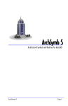
1.3.2 Machine Control Unit
The Machine Control Unit (MCU) is the microprocessor-based computer that
control the operation of the NC machine. It is the heart of CNC system by which the
information is exchanged from the host computer to the NC machine. The information is
manipulated using hardware logic and software programs, and finally stored in the
machine memory. The basic elements of a computer numerical control system are shown
in Figure 1.2 NC programs are downloaded from the host computer to the MCU, or
uploaded from the MCU to the computer. The MCU directs the NC machining operations
according to NC codes, and received the information about tool change and machine
position from the NC machine.
Host
Computer
MachineControl
Unit
NC Machine
Figure 1.2. The basic elements of a CNC.
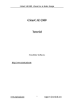
Five major functional units are in a machine control unit. Each unit performs a
specific function, and all units together execute the programmed instructions. The Figure
1.3 shows the relationship among the five units. The solid lines with arrows represent the
flow of the data. The dashed lines with arrows represent the flow of timing and control
signals.
Control
•
-
-
-
.
\y
\y
Input
Output
Memory
To operator and
mac•hine interface
From operator an d
machine interfac e
Arithmetic
<
-
-
•
-
Figure 1.3. Five major functional units of a computer numerical control system.
(Bakerjian, 1989)
There are three basic operating functions for a machine control unit:
1. MCU controls the normal running of the machine. This running may either be
controlled by NC programming or be under direct manual control by the machine
operator as a standard machine tool.
2. MCU provides useful machine status on the display screen. It displays the machine
position and programmed goal position, spindle speed, feed rate, current cutting tool,
alarm, and other information. The operator can verify correct running of the machine
and prevent damage by checking the machine status.
MCU can manipulate the stored NC programs. The control unit can download the NC
programs from the CAD system from a linked computer, allow operator to edit programs
by using the keyboard on the MCU. The ability of uploading programs back to the CAD
system is also provided. In distributed numerical control (DNC) where NC programs
remain on a computer and are electronically transmitted to the MCU, it can direct the
machine by using a communication port (RS232) rather than from stored programs.
1.3.3 NC Machine Motions
It is known that there are three major NC machine motions.
1. Point-to-point is the simplest type of the machine motions. It moves a tool from one
specified position to another while some operations are carried out. The actual path
between these two positions is not too significant to be considered. For instance,
during the drilling operation, only point-to-point control may be required.
2. Straight-cut is a kind of the machine motions which moves the cutting tool paralleled
to one of the machine axis, such as X axis.
3. Contouring is the most complex machine motion with the capability of point-to-point
and straight-cut control. It also provides simultaneous precise control of more than
one machine axis. For example, the linear interpolation ( movements between
positions by straight lines) and the circular interpolation ( movements as arcs or
circles), are required contouring control.
The speed of machine motion is controlled by the feed rate (F code) in NC
program. Some additional motions are described as the control of the operation spindle
speed, the coolant supply, the tool changes, and so on.
1.3.4 Cathode Ray Tube (CRT)
The latest CNCs are using a visual display of NC programming and other
parameters by the cathode ray tube (CRT). It is very similar to a TV screen. The upper
right part of Figure 1.1 is a CRT. The most typical feature of CRT is that the screen not
only displays the full operational and parametric data, the running program, but also
generates graphics. Moreover, CRT also displays some error message to help perform
high quality products.
1.4 Integration of CAD/CAM for CNC Machining
1.4.1 Computer-Aided Design and Manufacturing (CAD/CAM)
Pasemann (1986) pointed out that CAD/CAM integration means first of all well
functioning interfaces between these systems providing internal or external
communication of product data. It is recognized that the different steps in the
development of a manufactured product are interrelated and can be accomplished more
effectively and efficiently with computers. CAD/CAM system combines the precision of
electronic graphics and the mathematical processing power of the digital computer to
provide many diverse capabilities. The CAD/CAM applications refer from engineering
analyses to manufacturing controls. Typically, the connection that CAD/CAM provides
between geometric models and the number crunching power of computers allows it to
provide vast productivity improvements in numerical control (NC) system. Overall,
CAD/CAM integration is a key to the manufacturing which improves the productivity,
efficiency, and profitability in current industry.
Several functions of CAD/CAM systems are described below:
1. A CAD/CAM system can automatically generate production information based on the
geometric model contained in the CAD part. This information can be used in many
ways during the manufacturing process. For instance, it may be formatted numerical
control information which is used in a variety of ways by directing it to different
numerically controlled machines or systems, or it may be milling information to direct
a milling machine to mill a surface as described in the CAD part.
2. A digital computer of the CAD/CAM system provides the capability for writing and
using a variety of computer programs for calculations or for processing information.
The capabilities of this digital computer are not specific to CAD/CAM, but can be
developed on any computer.
3. The communications capabilities which provide a method for exchanging information
with other computers via the established telecommunications networks (such as
RS232) are also used in CAD/CAM system. This information may be numerical
control information, CAD drawing information, or any other type of information.
All-sidedly, the integration of CAD/CAM is not only based on the physical part of
product being produced, but also on the data that define and direct each step in the
manufacturing process.
1.4.2 CAD/CAM in CNC Machining
After a NC programmer finishes programming, and before an operator begins to
manufacture the part, it is very helpful for them to watch a graphic representation of the
path superimposed on the part geometry. A CAD/CAM system can be developed to
generate automatically the optimal cutter path, to move from one machining feature to the
next.
Current research focuses on the NC tool path simulation with the ability to display
the cutter path superimposed on the part geometry. CAD system displays cutter location
on a color screen rather than in black and white screen. Additionally, the CAD/CAM
system suggests that the geometry as a shaded image is in one set of color, and then the
tool path is in a contrasting color. Cutting paths are as solid lines and rapid movements in
air are seen as dotted lines. Therefore, CAD/CAM system makes CNC manufacturing
process simulation more powerful and clear than any other simulations.
1.5 Research Objectives
TRIAC vertical NC milling machine is used to practice the part design, NC
programming and CNC machining by the students in Industrial Engineering Department
at Texas Tech University. It was made in England in 1985. Since it has been used for
education for about ten years, there are several problems occurred during recent
operation.
1. The alpha numeric keyboard used to allow full manual data input. But currently, some
of the keys are stick up and can not be used to enter data into the NC machine, such as
key G81 and Mirror X. RS-232 communication port is used to transfer the NC
program from the host computer to TRIAC milling machine.
2. MCU lost its control about some of the functions, such as tool offset function.
3. The alarm for error checking in TRIAC machine is incomplete because of loss
functions.
4. The tool path simulation on TRIAC CRT may be generated without checking the
error completely. Therefore, the tool path simulation is failure, too.
Because of the reasons mentioned above, it is dangerous to download the NC code
and run the machine without checking the program for errors. Currently, the approach to
Computer Numerical Control programming is rapidly developed. A graphics based tool
path simulation system is necessary to enable the utilization of graphics for the NC
programming and extend the NC operating capability by using simulation. The objectives
of this research is going to build up a software interface for TRIAC NC machine to verify
the NC programs' syntax, semantics, and generate the NC tool path in AutoCAD
environment. This software package is the bridge exchanged data between CAD
geometry data and NC codes. CAD-interfaces are the most important topic in the realm of
CAD/CAM integration.
The graphics-based simulation system developed includes a CAD module, an
error control and tool path simulation software, a CNC machine, and a communication
package. The simulation software is written for the MS-DOS Operating System. In this
integrated system, the blank drawing and the tool path are prepared in the CAD module
using different line types and colors. The procedure in graphical simulation is that the
simulation software reads the NC code, checks the program syntax error, converts the NC
code into AutoCAD script file and generates the tool path in AutoCAD environment.
Although currently there are many software packages that have been developed to
help assist the NC programmers. This graphical simulation software developed here is
customized for the use of TRIAC milling machines. It assists to produce high quality,
precision products more efficiently, and fulfills education requirements.
CHAPTER 2
TRL\C NC MILLING MACHINE
The TRIAC vertical milling machine is located in the manufacturing lab of
Industrial Engineering Department at Texas Tech University used by the students to
perform course projects. It is a computer based programmable numerical control unit,
which utilizes the advances in microprocessor technology to control a 3-axis activated
stepper motors. TRIACs NC programming format is according to the International
Standard incorporating G and M codes.
Programming facilities include integral spindle control, circular, repeat, fixed or
floating datum, inch or metric and absolute or incremental programming, dwells, program
scaling, mirror imaging, tool diameter and length compensation.
The total memory of the control unit is 750 blocks.
2.1 Basic NC Programming for TRIAC Milling Machine
This section is to be used as a introduction to the NC programming, especial for
the TRIAC milling machine.
2.1.1 The Coordinate System
The diagram below shows a top view of the grid as it would appear on the
machine tool. This view shows the X and Y axes as the operator faces the machine tool.
Tool moves away to the right of zero is positive increase; away to the left of zero is
negative increase. Tool moves away from operator is positive increase along Y direction;
and moves close to operator causing a negative increase.
10
Y+
X-
0
x+
Y-
Operator
Figure 2.1. Coordinate system of TRIAC NC machine
The work zero in the Z-axis is usually set at the top of the part surface, this will be
entered in the tool length offset as a negative value. Tool moves above the part surface is
positive increase, otherwise, negative increase.
2.1.2 Machine Axis Format
TRIAC machine is a three axis mill. The illustration shows the positive and
negative, indicating the direction of the tool movement. It is very important concept to
understand that all motions programmed are the movements of the tool, not the
movements of machine table.
Originally starting TRIAC from a cold start, there is no operation until machine
has been datumed. Each axis is driven to a limit switch, Z, Y, and X axis, respectively.
Each limit switch position is maximum positive motion for that axis. The machine
initially being the bottom left hand comer of the table for X and Y axes.
Figure 2.2 shows the machine axis format.
11
/N
Y+
Plan View
X+
ccw
/N
z+
Front View
>
/N
X+
z+
Left Side View
Y+
< :
Figure 2.2. TRIAC machine axis format
12
X-
Left forward movement of tool
X-i-
Right forward movement of tool
Y-
Tool moves away from the operator
Y+
Tool moves towards the operator
Z-
Downward movement of the tool
Z+
Upward movement of the tool
2.1.3 Absolute and Incremental Positioning
In absolute positioning, all coordinate points are given with regard to their
relationship to the origin, a fixed zero point, or considered as part zero. This is the most
common type of positioning.
Incremental positioning concerns itself with distance and direction. A new
coordinate is entered in terms of its relationship to the previous position, and not from a
fixed zero or origin. In other words, after a block of information has been executed, the
position that the tool is now at is the new zero point for the next move to be made. An
example of the use of the incremental system is in Figure 2.3. Note that to move from
X4.0 to X2.0 on the scale, an incremental move of X-2.0 was made, even though the
move still places the tool on the plus side of the scale. Therefore the move was
determined from the last point, with no regard for the zero position. The + and - signs are
used in terms of direction, and not in regard to the position of zero.
XO
1
2
3
4
X-2
Figure 2.3. An example of an incremental move.
The types of coordinate position system are described in NC program as follow:
G90
Absolute dimensional positions.
G91
Incremental dimensional positions.
13
2.1.4 Tool Length Offsets
Tool length offsets are defined as a measured distance from the machine fixed
zero to a plane at which the part is programmed, usually the top of the workpiece.
To program the Z axis, the location of the tip of the tool is be considered every
time. At the setup period, the tool is moved until its tip is reached the top of the
workpiece. The machine control automatically adds or subtracts the tool length and places
the tool point at the desired location.
Figure 2.4 provides an example of tool offset. If Z offset for the tool is 60mm,
then the parameters of movement for that tool are:
Z - H l 7 5 ~ Z - 6 0 =235 mm
Z 175
Tool
>
en
Top Worksurface
zo
M
Part
t
Z -60
t
Machine Table
Figure 2.4. An example of tool movement parameters
2.1.5 Preparatory Command (G-code)
NC machines receive instructions as a sequence of blocks which contain different
commands to control machine operations and set parameters, dimension and speed. The
preparatory function (G-code) prepares the machine control unit with an operation,
especially involving a cutter movement^
14
Table 2.1. G Codes
GOO or GO
GOlorGl
Rapid Motion Positioning. All motions rapid traverse in linear mode.
X
Optional X-axis motion command
Y
Optional Y-axis motion command
Z
Optional Z-axis motion command
Linear Interpolation Motion. It is the mode of program to move the
tool in a straight line that is parallel to an axis or at some angle to an
axis. Depressing X, Y or Z key will default to GOl linear mode.
G02 or G2
F
Feed rate in inches (mm) per minute
X
Optional X-axis motion command
Y
Optional Y-axis motion command
Z
Optional Z-axis motion command
Clockwise Circular Interpolation Motion. It is to be used when the
tool is to follow the path of a circular arc while moving in a
clockwise direction for X and Y axis.
F
Feed rate in inches (mm) per minute
X
Optional X-axis motion command
Y
Optional Y-axis motion command
Z
Optional Z-axis motion command
XC
Circle center for X-axis
YC
Circle center for Y-axis
15
Table 2.1. Continued.
G03 or G3
Counterclockwise Circular Interpolation Motion. It is to be used
when the tool is to follow the path of a circular arc while moving in a
counter-clockwise direction for X and Y axis.
F
Feed rate in inches (mm) per minute
X
Optional X-axis motion command
Y
Optional Y-axis motion command
Z
Optional Z-axis motion command
XC
Circle center for X-axis
YC
Circle center for Y-axis
G04 or G4
Dwell. No Movement will occur while a timed dwell is performed.
GIO
Mirror X. It is for changing over the position and negative direction
of the X axis.
G12
Mirror Y. It is for changing over the positive and negative direction
of the Y axis.
G13
Cancel Mirror Y. This function cancels Y mirror function.
G20
Program Scale. This function allows a program scale 0.01% to 650%
to be entered into the program.
G54
Program Offset. This function allows an incremental offset within the
program.
G70
Imperial Units. This function selects imperial units for the program
G71
Metric Units. This function selects metric units for the program.
G81
Repeat Function. This function selects a repeat loop which will allow
a programmed sequence to be repeated with specified offsets.
G90
Absolute Input. This function selects absolute format.
G91
Incremental Input. This function selects incremental mode, and
allows incremental input with absolute display.
16
2.1.5.1 Repeat Function (G81)
The repeat facility enables specified sections of a programmed sequence to be
repeated. It is only permitted within a programmed sequence. The data required to specify
a repeat is:
1. The start block number to be repeated, this must be linear block with all axes
defined. X, Y and Z dimension within the start block.
2. The end block number to be repeated.
3. The number of repeats required.
4. Feed. Entering a feed into the repeat loop will change all feeds programmed
within the loop to the new feedrate. Omitting a feedrate value will leave all
feeds as initially programmed.
When each repeat is programmed the control checks all the dimensions being
repeated, adding the programmed offset to the number of repeats to ensure that the
machine limits are not exceeded. The example in Figure 2.5 and Table 2.1 show how to
use the repeat function G81.
ooo
ooo
€> O Q O
10
10
10
10
Figure 2.5. An example of NC drilling (6mm depth)
17
Table 2.2. NC code for the drilling example in Figure 2.4.
N
G
01
M
From
lo
REP
X
Y
z
F
03
02
00
3
03
00
04
01
-6
05
00
3
06
81
3
5
3
07
81
3
6
3
08
00
10
05
10
02
100
+10
+ 10
0
09
10
0
2.1.5.2 Mirror Imaging Function (GIO, G12)
The mirror imaging function provides the cutter transformation ability to mill a
contour or drill holes by inverse of one or more axes in another plane. Such "mirroring"
of a coordinate axis permits contour machining in the following relationship (Smith,
1993):
1. with the same dimensions;
2. at the same distance from the other axes;
3. on the other side of the "mirror axis", but as a "mirror-image".
Mirror function changes:
1. the sign of the coordinates of the mirrored axis. For example, when GIO mirror X is
used, the point (10, 10) is changed to be (-10, 10), and the sign of the coordinates of
the Y axis is not changed.
2. the direction of rotation. When circular interpolation (G02, G03) is occurred in the
NC program, the mirror function changes the direction of rotation from clockwise to
counter-clockwise, or vice versa.
18
The mirror function is always in relation to the mirror axis, such as X axis (when
using GIO Mirror X), according to which the contours can be mirrored and machined in
the exact position. In order to achieve this axis symmetry, a zero position of the
coordinate system needs to be set before any mirror function being activated in the
program.
The following Figure 2.6 demonstrates using mirror function to repeat milling a
triangle in negative quadrant.
Figure 2.6. An example of using mirror X and Y function (3mm depth)
19
Table 2.3. NC code for the milling example in Figure 2.5.
N
G
01
00
02
M
From
To
REP
X
Y
z
0
0
3
10
10
3
F
03
03
00
04
01
05
01
50
10
06
01
60
40
07
01
10
10
08
00
09
00
10
10
11
12
12
81
-3
75
75
3
3
0
0
-80
0
1
9
05
13
14
11
15
13
16
00
02
17
2.1.5.3 Scale Function (G20)
Scale function (G20) is an other very helpful cutter transformation function,
which enlarges or reduces the milling contours. A typical schematic of the "scaling" of a
contour is shown in the following Figure 2.7, demonstrating and clarifying the range of
size variation when using scaling factors. The scaling factor determines the enlargement
or reduction of contours, and automatically calculates the new dimensions and
coordinates. For instance, G20 50, means to reduce the contours 50% with the scaling
factor 50.
20
[^
Figure 2.7. Scaling of a Contour
The following example is using scaling function to milling a contour in different sizes.
5/6 Scale1/2 Scale(0,0)
*
38
»4
27
>
Figure 2.8. An example of using scale function ( 3mm depth)
21
Table 2.4. NC code for milling a part in an example in Figure 2.7.
N
G
Scale
01
M
From
Jo
REP
X
Y
z
0
0
3
F
03
02
00
03
01
04
01
38
0
05
01
65
75
06
01
0
120
07
00
08
00
09
10
10
81
11
11
12
20
13
81
14
20
15
81
-3
75
75
3
0
0
3
7
1
0
0
3
11
1
0
0
3
11
1
0
0
83.33
50
02
16
2.1.6 Miscellaneous Command (M-code)
Miscellaneous functions (M-code) are provided to designate a particular mode of
operation, typically to switch a machine function on or off, such as coolant on or off and
spindle on or off.
22
Table 2.5. M Code
M02 or M2
Program End. This function will end the program. Once reaching this
point the spindle will stop and the tool will retract to its home
position.
M03 or M3
Spindle Forward. The M03 will start the spindle rotation in clockwise
direction. The desired spindle speed (RPM) value can be entered.
M04 or M4
Spindle Reverse. The M04 function starts the spindle rotation in
counter-clockwise direction.
M05
Spindle Stop.
M06
Change Tool.
2.1.7 Other Commands
There are other commands classified as follow:
•
Sequence number ( N-code) is used to identify the number for the block in ascending
numerical order.
•
Feed functions ( F-code) are used to set the cutter feed rates to be applied.
•
Speed functions( S-code) are used to specify the spindle speed.
•
Tool functions ( T-code) are used to specify the cutter to be used.
•
End of block character ( L ) is used in TRIAC NC machine to signify the end of the
block.
•
Coordinate characters (X, Y, Z codes) are used to specify the geometric data of the
coordinate system.
2.1.8 Guidelines for NC Programming for TRIAC Milling Machine
There are a few guidelines which govern the use of all codes for programming the
TRIAC controls.
23
1. One G Code is permitted per block.
2. One M Code is permitted per block.
3. M and G codes cannot be entered on the same line.
4. There are modal G codes which, once established, remain effective until
replaced with another code from the same group.
5. In order to perform the necessary machine operations, there are several
information need to be specified, such as tool selection (T code), spindle speed
(S code) and feedrate (F code).
6. The workpiece dimension, the tool travel and the axis of the slideways should
be considered before programming.
7. There are non-modal G codes which, once called, are effective only in the
calling block, and are immediately forgotten by the control.
8. The M code will be the last item of code to be performed, regardless of where
it is located in the line.
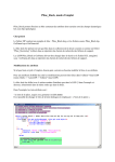
2.1.9 An Example of NC Programming
In the following example of NC programming. Repeat G81, Mirror Image GIO,
G12, and Scale Function G20 are utilized to mill three quarter circles. An absolute NC
code for Figure 2.9 is show in Table 2.6:
Table 2.6. NC code for Figure 2.9
N1M3L
N2G00X10Y0Z10L
N3G01Z-5F50L
N4G01X30L
N5 G03 XIO Y20 XCIO YCO L
N6G01 YOL
N7G01Z10L
N8 GOO XO YO L
N9G10L
N10G81R2E8N1X0Y0L
NllGllL
N12G20 150L
N13G81R2E8N1X10Y0L
N14M05L
; Spindle Forward
; Move to point (10,0,10)
; Mill 5mm into the part
; Mill the part to the point (30,0)
; Mill an arc to point (10,20) with center (10,0)
; Move to the point (10,0)
; Retract the tool 10mm above the part
; Move the tool to the point (0,0)
; Mirror X function
; Repeat program loop from N2 to N8 once
; Mirror X function cancel
; Scale 150%
; Repeat program loop from N2 to N8 Once
; Spindle stop
24
(-10,20)
/
f
(-30,0)
(10,0)
(-10,0)
(30,0)
(45,0)
iro,o)
)
(10,-20)
. ^ ^
(10,-35)
y
/
r
Figure 2.9. A sample part for milling ( 5mm depth ).
2.2 Current Working Conditions of TRIAC Milling Machine
TRIAC milling machine's longitudinal travel (X) is 290mm(l 1.5"); cross travel
(Y) is 170mm (6.5"); vertical travel (Z) is 235mm(9.5"). The following Figure 2.10
shows the TRIAC machine axis travel ranges. When machine X and machine Y are equal
to zero, the tool head is at a point near the front left hand corner of the table. When
machine Z is equal to zero, the tool is at maximum distance from the top surface of the
stock.
25
Figure 2.10. TRIAC milling machine axis travel ranges
TRIAC uses RS232C serial link to download NC programs from the computer to
the machine control unit, or download the programs from the machine to the computer.
Since TRIAC is an obsolete NC milling machine, there exist some limitations of
NC programming by current working conditions of TRIAC machine:
1. The machine axis travel range of TRIAC machine is X=290mm, Y= 170mm
and Z= 235mm. This should be considered before programming.
2. Some of the function keys are out of control. As a result, it is better to use data
transfer from computer to NC machine than to use manual edit and
manipulation.
3. Several functions in the program are useless, such as M20, M21, G40, G41,
G42,G70,G71.
4. M code and G code can not be in the same block.
26
5. No more than two M-code or two G-code can be in the same block.
6. Blank lines are not accepted.
7. Lower case letters can not be accepted.
8. Speed command ( S-code) and other NC code can not be in the same block.
9. Only one feed rate command (F-code) can be specified in a block, and need to
put at the end of the block.
10. Every block must end with the letter "L".
11. The scale range is 0.01 % to 650%.
12. The arc should begin and end in the range of one quadrant. In other word, a
circle need to be programmed by using the combination of four arcs.
2.3 Advantages of Using Simulation Software for TRIAC Machine
Manual programming demands a NC programmer to determine the manufacture
process and the machine operation directly without using the aid of computers. However,
much detailed calculation is required to realized the cutter path. It causes potential errors,
such as incorrect calculation and the risk of making mistakes in entering data. The
simulation software is used for error detection, which can save valuable production time,
especially for the TRIAC NC milling machine. The advantages of using graphical
simulation software for TRIAC machine are:
•
The tool path graphics can be simulated with several available views. From those
views, the programmers or the operators can check the tool path step by step.
•
The graphical simulation software can generate an original stock drawing with three
alternative views in AutoCAD.
•
Every block in NC program is checked by this simulation to keep it correct when
transfer to the TRIAC milling machine.
•
There are error message to help the programmers make changes of their NC
programs.
•
The rapid tool movement and cutting movement are demonstrated in different colors.
27
The simulation reduces the time for editing NC programs. Because of different key
board and key board position, it is much faster to key in on the computer than key in
on the TRIAC milling machine.
28
CHAPTERS
THE STRUCTURES OF THE SIMULATION SOFTWARE
The following flow chart shows the structure of the tool path simulation software.
The first part of the software is using C language program to verify the NC codes and
transfer them into AutoCAD script file. The second part of the software is using
AutoCAD basic commands and AutoLISP language program to generate a graphic with
stock size in three different views. Finally, the two parts combine to create a NC tool path
in AutoCAD.
Figure 3.1. Structure of the NC simulation software.
29
3.1 AutoCAD
AutoCAD is a general purpose Computer-Aided Design (CAD) program for
preparing two-dimensional drawings and three-dimensional models. AutoCAD is used in
fields as diverse as Architecture, Engineering, Geographical Information Systems,
Desktop Publishing, Electrical Design, and Process Industry Design. It provides a full
range of drafting tools that let user create accurate and realistic images that meet the
ANSI standards for drafting (Autodesk, Inc. 1992).
From the AutoCAD Tutorial (1992), it states that AutoCAD is a multi-purpose
software package that can be used in many different applications, disciplines, and
environments. It uses support files to store menu definitions, load AutoLISP programs,
define linetypes, define hatch patterns, and so on. Many of the support files in AutoCAD
are ASCII files and can be edited with a simple text editor. These files are not integral to
AutoCAD, and can be customized so that AutoCAD works the way the user want it to.
The graphical tool path simulation is based on AutoCAD drafting commands. The
following commands are used to modify this simulation software:
•
SCRIPT command,
•
DELAY command.
The features covered in the simulation software are list as follows:
•
Modifying the acad.pgp file,
•
Adding an external command to the acad.pgp file.
At first, the AutoCAD basic commands are used to create a plan view. A stock is shown
with a plan view in the upper-left viewport, a side view in the lower viewport, and an
isometric view in the right viewport. Viewport let user work with different views of the
same drawing. The second, AutoLISP programming language is used to control the
contour and the size of the stock. The third, script file provides a continuously running
displays for the tool path demonstration.
30
3.1.1 Drawing Entity
AutoCAD creates drawing by using drawing entities, such as Lines, Arcs,
Polylines and Circles. An entity is a predefined element that a drawing is modified by the
means of commands. The following table describes the drawing entity types which
provided by AutoCAD.
Table 3.1. Drawing entities in AutoCAD (Autodesk, Inc., 1992)
Entity type
Lines
Description
Drawn with various dot-dash linetypes. When drawing a line segment,
provide either 2D (x, y) or 3D (x, y, z) coordinates.
Arcs and
Drawn with various dot-dash linetypes. Several methods are provided
Circles
for drawing arcs and circles.
Points
Appear as dots, squares, circles, Xs, or any combination of these. Point
entities can be located by using either 2D or 3D coordinates.
Text
Appears in various fonts with any size and orientation.
Traces
Two-dimensional, solid-filled lines of any width user specify.
Solide
Two-dimensional, solid-filled triangular, or quadrilateral objects.
Shapes
Small objects which can define outside AutoCAD and place in the
drawing with a specified scale and rotation.
Blocks
Compound entities formed from groups of other entities (or blocks).
Attributes
Attach constant or variable text information to each instance of a Block.
Dimensions
Compound entities similar to Blocks, containing all lines, arcs, arrows,
and text constituting a dimensioning annotation.
PolyLines
2D connected line and arc segments, with optional dot-dash linetypes,
width, and taper. Commands are provided to construct ellipses, regular
polygons, filled circles, and doughnuts using polylines.
3D
Polylines
3D objects composed of straight-line segments (but no arcs, width,
taper, or quadrilateral plane sections.
31
Table 3.1. Continued.
3D Faces
3D triangular or quadrilateral plane sections.
3D Meshes
3D polygon meshes of rectangular topology. Commands are provided to
construct ruled surfaces, surfaces of revolution, and tabulated cylinders
using 3D Meshes.
Polyface
Polygon meshes of arbitrary topology. Defining a polyface mesh allows
Meshes
user to avoid having to create many unrelated 3D face with coincident
vertices.
Viewports
Rectangular areas in paper space that contain a view of model space.
3.1.2 Original Stock Drawing by Using AutoCAD Basic Commands
The following steps are used to perform the original stock drawing in AutoCAD.
This AutoCAD drawing is in Appendix B.
Enter AutoCAD R12. C:\> acadrU.
Command: new
Command: Units
(1)
Enter choice: 2 (Decimal)
Number of digits to right of decimal point (0 to 8) <4>: 4
Systems of angle measure, enter choice, 1 to 5 <1>: / (Decimal degrees)
Number of fractional places for display of angles (0 to 8)<0>: 0
Enter direction for angle 0 <0>: 0 (East 3 o'clock = 0)
Do you want angles measured clockwise? <N>: Y
Command: limits
(2)
Reset Model space limits:
ON/OFF/<Lower left comer> < 0.0000,0.0000>: Enter
Upper right comer <12.0000, 9.0000>: 29.0000,17.0000
Command: graphscr
(3)
32
Command: ddrmodes
(4)
Snap: on
Grid : on
X Spacing: 0.5000
X Spacing: 0.5000
Y Spacing: 0.5000
Y Spacing: 0.5000
Command: zoom
(5)
All/Center/Dynamic/Extents/Left/PreviousA^maxAVindow/<Scale(X/XP)>:A
Command: zoom
All/Center/Dynamic/Extents/Left/PreviousA^maxAVindow/<Scale(X/XP)>:O.P
Command: elev
(6)
New current elevation <0.0000>: 0.0000
New current thickness <0.0000>: 2.0000
Command: line
From point: 0.0000, 0.0000
To point: 20.0000, 0.0000
To point: 20.0000,15.0000
To point: 0.0000,15.0000
To point: 0.0000, 0.0000
Command: tilemode
(7)
New value for TILEMODE <\>.0
Entering paper space. Use MVIEW to insert Model space viewports.
Regenerating drawing.
Command: mview
(8)
ON/OFF/Hideplot/Fit/2/3/4/Restore/<First Point>: 3
HorizontalA^ertical/Above/Below/Left/<Right>: right
Fit/<First Point>: 0.5000,0.5000
Second point: 12.0000,8.5000
Command: Mspace
(9)
Click the upper-left viewport.
33
Command: vpoint
(10)
Rotate/<View point><0.0000,0.0000,1.0000>: 0.0000,1.0000, 0.0000
Regenerating drawing.
Click the right side of the viewport.
Command: vpoint
Rotate/<View pointxO.0000,0.0000,1.0000>: 1.0000,1.0000,1.0000
Regenerating drawing.
1. Units. The distance between two coordinate points is measured in units. There are
several kinds of units in AutoCAD, such as scientific, decimal, engineering,
architectural, and fractional.
2. Limits. AutoCAD drawings are always in a rectangular area. The drawing limits
specify the potential size of the rectangle, expressed in X, Y drawing coordinates.
3. Graphscr. The command return AutoCAD to graphic screen.
4. DDEMODES. This command set the grid and snap on or off. The grid displays a
reference grid of points with desired spacing. Points entered in AutoCAD drawing can
be locked into alignment with an imaginary rectangular grid by the snap command.
5. Zoom. Zoom command increases or decrease the apparent size of the drawing in the
current viewpoint, and the actual size of the drawing remains constant.
6. Elevation and thickness. The elevation of a drawing is the Z value of the XY plane on
which its base is drawn. The thickness of a drawing is the length that object is to be
extruded above its elevation.
7. Tilemode. Tilemode is a system variable which controls access to paper space.
•
Tilemode On (1) = Enables uses VPORTS.
•
Tilemode Off (0) = Enables paper space and Viewport entities (uses MVIEW).
AutoCAD clears the graphics screen to let user create one or more viewports.
8. MVIEW. MVIEW operates in paper space to create new viewports, turn viewport
display on or off, and remove hidden lines.
34
9. MSPACE. MSPACE change paper space to model space.
10. Vpoint. Vpoint set the viewing point for the current drawing. AutoCAD regenerates
the drawing, and displays the drawing as seen it from the point in model space.
•
View point (0,0,1)
A top view.
•
View point (1,0,0)
A front view.
•
View point (1,0,0)
A right view.
•
View point (1,1,1)
A top, right, front view.
3.1.3 Program Parameters File
The acad.pgp is the AutoCAD program parameters file, which stores command
definitions used by AutoCAD. This file is divided into two sections: the first section
defines external commands, while the second section defines command aliases. In
addition, this file can contain comments, which must be preceded by a semicolon (;).
(Autodesk, Inc. 1992). This file can be modified with any text editor. When AutoCAD
starts, it searches the library file path and reads the first acad.pgp file it finds, ignoring
other files with the same name. AutoCAD reinitializes the acad.pgp file each time when
open a new or existing drawing.
Other programs might be executed in AutoCAD in this manner include:
Internal DOS command, such as type;
Other DOS or UNIX utilities, such as diskcopy or grep\
Text editors and word processors;
Database managers;
Spreadsheets;
Communications programs;
User- supplied programs.
In order to run another program from within AutoCAD, the name of the program
and other related details must be known by AutoCAD. This information need to be
supplied in the external commands section of acad.pgp.
35
When the external commands are defined in acad.pgp, each line describes a
program that can be executed from within AutoCAD. The new commands are considered
to be a list of custom AutoCAD commands.
Each line in acad.pgp that defines an external command has five fields, delimited
by commas.(Autodesk, Inc. 1992). The five fields in acad.pgp file are described in Table
3.2.
Table 3.2. Five fields in acad.pgp file which defines external commands.
(Autodesk, Inc., 1992)
Command
The AutoCAD external command to be added. This is what will be
name
entered at the Command: prompt. It must not be an internal
AutoCAD command or it will be ignored .
File command
This constant string is sent to the operating system for execution
when enter the command name. It can be any valid command to be
executed at operating system's command prompt. The string might
include switches, parameters, and so on.
Memory
This field serves to maintain compatibility with previous versions of
reserve
AutoCAD. Although AutoCAD does not use the value in this field, a
number (typically 0) must be present.
Prompt
This field, if supplied, specifies a prompt to be displayed to the user.
The response to this prompt is appended to the constant command
string supplied by the file command field or specifies a block name.
Return code
This is an optional bit-coded parameter. These integer values can be
added together in any combination to achieve the result user wants.
The value are defined as follows:
0
Return to text screen
1 Load DXB file
2
Construct block from DXB file
4
Return to previous screen mode
36
Here the acad.pgp file is used to define an external command ~ TRIAC.
AutoCAD ignores blank lines and all text to the right of a semicolon. The following is an
example of an acad.pgp external commands section, the external command "TRIAC" is
added:
DEL, DEL,
0, File to delete: ,4
DIR,DIR,
0, File specification: ,0
EDIT, EDLIN,0, File to edit: ,4
SH,,
0, *0S Command: ,4
SHELL,,
0,*OS Command: ,4
TYPE, TYPE,
0, File to list:, 0
TRIAC, TRIAC,
0,
,4
The first TRIAC is the AutoCAD external command name. The second TRIAC is
the file command. It is sent to the operating system for execution when the command
name is entered. The number '0' presents a field which serves to maintain compatibility
with previous versions of AutoCAD. The next field is called prompt field. It specifies a
prompt to be displayed after the command is used. TRIAC command does not need
prompt. Hence, keep the field empty. After the command is executed, the number '4'
called return code is used to return to previous screen mode. The defined external
commands are for interactive use only.
3.2 AutoLISP Programming Language
One of the most powerful capabilities for extending AutoCAD is AutoLISP.
AutoLISP, an integral part of AutoCAD, is a specialized implementation of the LISP
programming language. It is used to create new AutoCAD commands and automate
37
repetitive tasks. AutoLISP lets users write macro programs and functions in a powerful
high-level language suited to graphics application. (Autodesk, Inc. 1992).
3.2.1 AutoLISP Data Types
There are eight major data types in AutoLISP programming language (Table 3.3).
Table 3.3. Data types in AutoLISP language
Data Type
Symbols.
Function
Example
Symbols are used to
The following example shows the setq
store values.
function to set the symbol pi to the point
value (4.0,5.0):
(setq pi '(4.0 5.0))
Lists
Lists stores numbers;
For instance, (3 4) indicates that a 2D point.
related values are in
The first value is the X coordinate and the
one symbol.
second value is the Y coordinate. (3 7 5)
expresses a 3D points. The first value is the
X coordinate, the second value is the Y
coordinate, and the third value is the Z
coordinate.
Strings
Strings have unlimited
length.
Integers
Integers are values
entered without a
decimal point.
38
Table 3.3 Continued.
Real numbers Real numbers are
numbers entered with
a decimal point.
File descriptors When an AutoLISP
The example below opens a file called
function needs to
temp.lsp, allowing it accessible to other
access a file, its label
functions for writing, and assigns the value
must be referenced. At
of file descriptor to the symbol data:
this moment, file
descriptors are
(setq data (open "temp.lsp" "w"))
alphanumeric labels
- return
<File: #34662>
assigned to those files.
AutoCAD
An entity name is a
entity names
pointer assigned to
entities in a drawing.
AutoCAD
Selection sets are
selection sets
groups of entities
- return <Selection set: 1>
which can be added or
This example assigns the selection set ~ the
removed.
previously selected objects to the symbol su.
For instance: (setq su (ssget "P"))
AutoLISP names variables with an alphabetic character as the first character.
There are four kinds of variables:
1. integer,
2. real,
3. point,
4. string.
39
The AutoLISP setq function is used to assign values to variables. The format is as below:
( setq variable value )
3.2.2 Function Defining and Loading
Every AutoLISP expressions should be preceded by an opening bracket, and
should have a corresponding closing one. Such as:
(function-name
[arguments]..)
All of the AutoLISP functions can directly access to AutoCAD by enter the
function after "Command:". These functions are currently loaded, and when quit the
drawing, they will not be saved.
The AutoLISP load function is provided to save function definitions in files with
an extension of .Isp and load them in every drawing. During the file loading, all
expressions are evaluated. The defun function is used to store groups of functions in the
AutoCAD memory for later execution. The unique character of AutoLISP is that it can
add new commands to AutoCAD. The C: name function make this character realizable.
For example, the following AutoLISP file is used to draw a square on AutoCAD by using
SQUARE command.
(defun C: SQUARE (/ pi p2 p3 p4 len)
(setq pi (getpoint "Enter the lower left comer:"))
(setq len (getdist pi "Enter the square length:"))
(setq p2 ( polar pi 0.0 len)
(setq p3 ( polar p2 (/ pi 2) len))
(setq p4 ( polar p3 pi len))
(command "pline" pi p2 p3 p4 "C")
)
40
Suppose the file name is exam.lsp. At first, load the function as
Command: (load "exam")
loads the file exam.lsp
And then for the sample C: SQUARE function, the new command looks like this:
Command: square
Enter the lower left comer: Select a point
Enter the square length : Enter a distance
3.2.3 AutoLISP Functions
AutoLISP provides all kinds of functions used in programming. This chapter only
describes several functions used in the tool path simulation software. These functions are
as follow: (Autodesk, Inc. 1992).
•
Function handling : (defun sym argument-list expr...)
Defines an extemal function with the name sym. The function name is
automatically quoted. Following the function name is a list of arguments, optionally
followed by a slash and the names of one or more local symbols for the function. For
instance:
(defun triac (x y)...)
Function takes two arguments
(defun triac (/ m n)..)
Function has two local symbols
(defun triac ( ) . . . )
Function has no arguments or local symbols
The defun function retums the name of the function being defined. The following
example define new function with defun and show the values retumed in AutoCAD:
(defun add20 (x) (+ 20 x)
retum ADD20
)
(add20 12)
retum 32
(add20-10)
retum 10
41
•
AutoCAD commands : (command [arguments] ... )
The function executes one or more AutoCAD commands and always retum nil.
The command function evaluates the arguments and sends them to AutoCAD in response
to successive prompts. It submits command names and options as strings, 2D points as
lists of two reals, and 3D points as lists of three reals. A null ("") is equivalent to press
the enter key on the keyboard. For example:
(setq ptl '(3 3 3) pt2 '(9 9 9))
(command "line" ptl pt2 "" )
Draw a line from (3,3,3) to (9,9,9)
Note: If the SCRIPT command is used with the command function, it should be the
last function call in the AutoLISP routine.
•
User input: (getreal [prompt])
This function prompts for user input of a real (floating-point) number and retum
that real number. For example:
(setq length (getreal))
•
Display control : ( princ [expr [file-desc]])
This function prints a message on the text screen or to an open file and retum
expr. Princ function prints expressions in a way that is readable by functions.
•
Entity handling : (endast)
This function finds the last entity in the drawing. It is frequendy used to obtain the
name of a new entity which has just been added via the command function. For example:
(setq m (entlast))
Set m to the name of the last main entity in the drawing
Symbol Handling : (setq sym] exprl [syml exprl] ...)
42
This function is a basic assignment function which sets the value of sym] to
expr], syml to exprl, and so on. It only retum the last expression. For example:
•
(setq a 10.0)
retum 10.0
(setq b (list 3 4))
retum (3 4)
(setq c "triac")
retum "triac
List manipulation : (list expr...)
This function creates a list from any number of expressions. It is used to define
the 2D or 3D point variable. For example:
(list 1 2 3)
•
return (1 2 3)
File handling : ( hodid filename [onfailure])
Loads a file of AutoLISP expressions.
3.2.4 Blank Size Control
The following AutoLISP language program in Figure 3.2 is provided to control
the blank size for the TRIAC milling machine.
(setq width 100)
(setq height 20)
(setq length 150)
(defun C: stock(/ len wid hei)
(princ "\nEnter the New Stock Length<" )(princ length)(princ">:")
(setq len (getint))
(if len
(setq length len)
Figure 3.2. AutoLISP program for the stock size control
43
)
(princ "\nEnter the New Stock Width <")(princ width)(princ">:")
(setq wid (getint))
(if wid
(setq width wid)
)
(princ "\nEnter the New Stock Height<")(princ height)(princ">:")
(setq hei (getint))
(if hei
(setq height hei)
)
(command "erase" "1" "")
(command "color" "green")
(command "pline" "0,0" (list length 0)(list length width)(list 0
width)"c")
(command "change" "1" "" "p" "t" height "el" (-height)"")
)
Figure 3.2 Continued.
3.3 SCRIPT Command
A script facility is provided to allow commands to be read from a text file in
AutoCAD. Utilizing this feature, users can predetermine the sequence of commands, and
invoke these commands when staring AutoCAD, and mn a script file within AutoCAD by
using SCRIPT command. Because the script facility provides an easy way to create
continuous running displays from one command to another, it is used for this simulation
software to demonstrate the tool path and show the manufacture process.
44
3.3.1 Script File
Script files are created by using a text editor outside AutoCAD. The file name
must be like "*.scr". The lines which begin with semicolons (;) are considered a
comment that provide descriptions of the file's contents and other relevant notes.
AutoCAD will ignore them when execute the script file.
For example, the script file should look like below:
snap on
Tum on snap
grid on
Tum on grid
linetype set continuous
Set linetype
color red
Select color
line 5.0, 4.0, 1.0
Draw a line from (5.0,4.0,1.0)
1.0,1.0, 1.0
to (1.0,1.0,1.0)
A script file directs a preordained sequence of commands either from the
operating system prompt or from inside AutoCAD. It performs tasks such as: (Autodesk,
Inc., 1992).
•
Changing the settings or display in current drawing;
•
Displaying a series of slides continuously;
•
Setting up new initial drawing configurations for Units, Limits, Snap and
Grid;
•
Adding predetermined layers to a drawing;
•
Ending one drawing and starting another.
The SCRIPT command execute a script file within AutoCAD. At first,
•
Enter AutoCAD and then enter:
Command: script
•
Respond with the script file name with an extension - "*. SCR", when AutoCAD
prompts.
45
3.3.2 DELAY Command Used in Script Facility
When the continuously mnning displays are shown, it is found that some
AutoCAD operations execute very quickly. As a result, it is difficult for people to see the
tool path simulation step by step. For example, if the script file draws a short line and
then erases it, the audience might not see what's happening on the screen. Therefore,
DELAY command provides a rather effective function to make a sufficient pause
between some operations. The DELAY command looks like this:
Command: delay
Delay time in milliseconds: 1000
The delay is designed to be about one millisecond per increment. Thus, the
command above will cause the next command to be delayed for one second. The larger
the number is, the longer the duration of the pause is.
The DELAY command is also used in script file. For instance.
LINE
11.0, 15.0,0.0
12.0,20.0,0.0
DELAY
500
LINE
1.0,20.0,0.0
2.0, 30.0, 0.0
This script file draws a line from point (11.0, 15.0, 0.0) to point (12.0, 20.0, 0.0) at first;
then the DELAY command provides an half second pause; and finally, the script file
draws an other line from (1.0, 20.0, 0.0) to (2.0, 30.0, 0.0).
46
3.4 C Programming Language
C programming language became known to the mass computer markets in the late
1970s. Most of today's familiar spreadsheets, databases, and word processors are written
in C. Here C is used to verify NC codes and convert them into script file.
3.4.1 The Stmcture of C Program
The stmcture of the C program is described in Figure 3.3. At the first, the C
program reads the NC codes, makes a Script file name to write. The second, C checks the
NC code errors by blocks. If there exist an error, the computer will generate a beep and
provide an error message to suggest the programmer to make a kind of change of the NC
code. If the codes are correct, C will continue to convert the X, Y, XC, YC codes to real
numbers. For example, it will change X 1.0 to 1.0 to prepare for the further calculation.
The third, this C program will calculate the lines' start point and end point, and the arcs'
center points, start point and end point. This process prepares all the geometry data for the
Script file. Finally, C transfers the NC code to Script file. And this Script file can used in
AutoCAD to generate the NC tool path.
47
Make Changes
to the NC code
Figure 3.3. Stmcture of C program in simulation software
3.4.2 NC Programs Error Check
Error checking is an important section in this C program. Factors needed to be
considered are list in the following table (Table 3.4).
48
Table 3.4. Errors in NC programs for TRIAC milling machine.
1. Use lower case letters instead of upper case
letters.
2. Block ends without using end block letter "L".
3. Block begins without using number of block
code ~ N code.
4. Two or more feedrates are defined in one block.
5. Spindle speed is defined with other NC codes.
6. More than one M codes are defined in one
Format Errors
block.
7. More than one G codes are defined in one
block.
8. M code and G code are defined in one block.
9. More than one XC codes are defined in one
block.
10. More than one YC codes are defined in one
block.
11. More than one X, Y, Z codes are defined in one
block.
1. There are XC, YC codes in GOO block.
2. G02, G03 blocks are defined without X, Y, XC,
Syntax Errors
YC codes in orders.
3. G20 block are defined without the scale.
4. G81 blocks are defined without R, E, N, X, Y,
codes in orders.
49
Table 3.4 Continued.
1. The Scale is greater than 650% or less than
0.03%.
Geometry Data Errors
2. The distance from the arc start point to its center
point is not equal to the distance from the arc
end point to its center point, or the difference
are greater than 0.03mm.
3. The angle or the arc is greater than 90°.
4. The feedrate is greater than 1000 RPM.
3.4.3 Calculations in C Program
3.4.3.1 The Calculation for the Geometry of Arcs
1. The Radius ( Figure 3.4 )
( X2, Y2 )
I/'
( XC, YC)
\
^
( X I , Yl )
Figure 3.4. Start point, end point and center of an arc.
V(X1- XC)2 + ( Y l - YC)2 - V(X2 - XC )2 + ( Y2- YC )^ <0.03 mm
This equation is used in C program to make sure that the distance from the arc
start point to the center of the arc is equal to the distance from the arc end point to the
center of the arc.
50
2. The Angle of Arc
a = arcsin [(Y2 -Y\)/^iX2-
XC)^ + (Y2- YC )2 ] > 7c/2
The equation above is used in C program to keep an arc milling operation not
exceed one fourth of a circle.
3.4.3.2 The Calculation of the Geometry of the Mirror Image
1. Mirror X ( Figure 3.5 )
pt2(X2,Y2)
len
pt3(XCl,YCl)
ptl(Xl,Yl)
A
pt0(Xa,Ya)
pt6
pt4
Figure 3.5. Milling a part by using Mirror X (GIO) function.
pt4:
X4 = X H - 2 * ( X a - X l ) = 2Xa-Xl
Y4 = Y1
pt5:
X5 = X2 + 2*(Xa-X2) = 2Xa-X2
Y5 = Y2
pt6:
X6 = XCl + 2*( Xa - XCl) = 2Xa - XCl
Y6 = YCl
The equations above are used in C program to calculate the coordinates of the
mirror X image.
51
2. Mirror Y ( Figure 3.6 )
pt2(X2,Y2)
pt3(XCl,YCl)
ptl(Xl,Yl)
•
pt6
pt0(Xa,Ya)
pt4
Figure 3.6. Milling a part by using Mirror Y (G12) function.
pt4:
X4 = X1
Y4 = Yl + 2*(Ya - Yl) = 2Ya - Yl
pt5:
X5 = X2
Y5 = Y2 + 2*(Ya - Y2) = 2Ya - Y2
pt6:
X6 = XC1
Y6 = YCl + 2*( Ya - YCl) = 2Ya - YCl
The equations above are used in C program to calculate the coordinates of the
mirror Y image.
52
3. Mirror X and Mirror Y ( Figure 3.7 )
pt2(X2,Y2)
ptl(Xl,Yl)
pt3(XCl,YCl)
ptO(Xa,Ya)
P^^
Figure 3.7. Milling a part by using Mirror X and Y (GIO, G12) function
pt4:
X4 = XI + 2*( Xa - XI) = 2Xa - XI
Y4 = Yl -h 2*(Ya - Yl) = 2Ya - Yl
pt5:
X5 = X2 + 2*( Xa - X2) = 2Xa - X2
Y5 = Y2 + 2*(Ya - Y2) = 2Ya - Y2
pt6:
X6 = XCl + 2*( Xa - XCl) = 2Xa - XCl
Y6 = YCl -h 2*( Ya - YCl) = 2Ya - YCl
The equations above are used in C program to calculate the coordinates of the
mirror X and Y image.
53
3.4.3.3 The Calculation of Geometry of Scaling ( Figure 3.8 )
pt4
pt2(X2,Y2) y L ^
X
\
Dts/
1
ptO(Xa,Ya)
ptl(Xl,Yl)
1
pt3
Figure 3.8. Milling a part by using Scaling (G20) function.
pt3:
Xa^tXl,
Ya = Yl,
X3 = Scale* XI,
Y3 = Yl
pt4:
Xa 7t X2,
Ya ^ Y2,
X4 = Scale * X2,
Y4 = Scale * Y2
pt5:
Xa = X5,
Ya = Y5
The equations shown above are used in C program to calculate the coordinates
after executing Scaling (G20) function.
54
CHAPTER 4
EXAMPLES OF TOOL PATH SIMULATION
In this chapter, several examples of using the graphical tool path simulation
software are provided (Figures 4.1-4.6). The purposes of create this simulation software
package are to help the NC programmer, especially for students, to check syntax errors in
programs, and generate a NC tool path in AutoCAD before executing the programs on the
TRIAC milling machine.
According to the procedure of using this software described in Appendix C, the
following examples include the figures of the milling parts, the NC programs for the
parts, and the graphics of tool path simulation of these milling operations in AutoCAD
environment. The NC codes include absolute positioning codes and incremental
positioning. That not only clarify the conception of different types of positioning, but also
ensure that the simulation software can be used in the absolute positioning as well as the
incremental positioning.
The script files are transferred from NC codes by the TRIAC.exe C program in
simulation software. They are mentioned in Appendixes D, E, and F. The tool path
simulation is generated by executing the script files.
The tool path simulation is shown in different linetypes and different colors on
computer screen.
•
The stock is displayed by green continuous lines;
•
The red dashed lines indicate rapid movement of the tool (GOO);
•
The yellow continuous lines indicate milling or drilling operation of the tool
(G01,G02,G03).
55
120
DESIGN NO.
A-1
MATERIAL
ALUMINIUM
Figure 4.1. Endmilling a simple part with lines and arcs, drilling operation
included.
56
•
Tool 1
6mm mill
•
Tool 2
8mm mill
•
Tool 3
4mm drill
The absolute NC code for the Figure 4.1 is shown below:
N1M06L
N2 M03 L
N4 GOO XI.00 Y5.00 Zl.00 L
N5G01Z-0.30F5.00L
N6G01 Y7.00F100L
N7G01X4.00L
N8 G02 X6.00 Y9.00 XC6.00 YC7.00 L
N9 G02 X8.00 Y7.00 XC6.00 YC7.00 L
NlOGOlXll.OOL
N i l GOl Y3.00L
N12 G02 X9.00 Yl.OO XC9.00 YC3.00 L
N13G01X2.50L
N14G01X1.00Y3.00L
N15G01 Y5.50L
N16G00Z0.30L
N17 M05 L
N18M06L
N19M03L
N21G00X4.10Y7.00L
N22G01Z-0.2F30L
N23 G02 X6.00 Y8.10 XC6.00 YC7.00 L
N24 G02 X7.10 Y7.00 XC6.00 YC7.00 L
N25 G02 X6.00 Y5.90 XC6.00 YC7.00 L
N26 G02 X4.90 Y7.00 XC6.00 YC7.00 L
N27 GOO Z0.2 L
N28G00X5.60Y7.00L
N29G01Z-0.2L
N30 G02 X6.00 Y7.40 XC6.00 YC7.00 L
N31 G02 X6.40 Y7.00 XC6.00 YC7.00 L
N32 G02 X6.00 Y6.60 XC6.00 YC7.00 L
N33 G02 X5.60 Y7.00 XC6.00 YC7.00 L
N34 GOO Z0.2 L
N35G00X2.40Y3.40L
N36G01Z-0.5L
N37G01 Y5.60L
Figure 4.1 Continued
57
N38G01X3.60L
N39 GOl Y3.40 L
N40G01X2.40L
N41G00Z0.5L
N42 GOO X3.00 Y3.50 L
N43 GOl Z-0.5 L
N44G01 Y5.50L
N45 GOO Z0.5 L
N46 M05 L
N47 M06 L
N48 M03 L
N50 GOO X7.00 Y4.0 L
N51G01Z-0.8F50L
N52G01Z0.2L
N53GOOX9.00Y5.00L
N54G01Z-0.8L
N55 GOl Z0.2 L
N56G00Y3.00L
N57G01Z-0.8L
N58G01Z0.2L
N59 GOO XO.OO YO.OO L
N60 M05 L
N61M02L
The incremental NC code for the Figure 4.1 is shown below:
N1M06L
N2 M03 L
N4 GOO XI.00 Y5.00 Zl.00 L
N5G01Z-1.30F5.00L
N6G01 Y2.00F100L
N7 GOl X3.00 L
N8 G02 X2.00 Y2.00 XC2.00 YCO.OO L
N9 G02 X2.00 Y-2.00 XCO.OO YC-2.00 L
N10G01X3.00L
N i l GOl Y-4.00L
N12 G02 X-2.00 Y-2.00 XC-2.00 YCO.OO L
N13G01X-6.5L
N14G01X-1.50Y2.00L
N15G01 Y2.5L
N16G00Z0.60L
N17M05L
Figure 4.1 Continued
58
N18M06L
N19M03L
N21GOOX3.50Y3.00L
N22G01Z-0.8F30L
N23 G02 XI.50 Y1.50 XCl.50 YCO.OO L
N24 G02 XI.50 YO.OO XCO.OO YC-1.500 L
N25 G02 X-1.50 Y-1.50 XC-1.50 YCO.OO L
N26 G02 X-1.50 Y1.50 XCO.OO YC1.50 L
N27G00Z1.0L
N28G00X-2.10Y-4.60L
N29G01Z-1.2L
N30 G02 X0.70 YO.OO XC0.80 YCO.OO L
N31 G02 X0.80 YO.OO XCO.OO YC-0.80 L
N32 G02 X0.80 Y-0.80 XC-0.80 YCO.OO L
N33 G02 X-.80 Y-0.80 XCO.OO YC0.80 L
N34 GOO Z0.4 L
N35GOOX-2.80Y-3.60L
N36G01Z-0.9L
N37G01 Y2.20L
N38G01X1.20L
N39G01 Y-2.20L
N40G01 X-1.20L
N41G00Z1.0L
N42 GOO X0.60 YO.OO L
N43G01Z-1.5L
N44G01 Y2.20L
N45G00Z1.0L
N46 M05 L
N47 M06 L
N48 M03 L
N50G00X4.00Y-1.60L
N51G01Z-1.8F50L
N52G01Z1.0L
N53 GOO X2.00 Yl.OO L
N54G01Z-1.8L
N55G01Z1.2L
N56 GOO Y-2.00 L
N57G01Z-1.8L
N58G01Z1.0L
N59G00X-11.00Y-3.00L
N60 M05 L
N61M02L
Figure 4.1 Continued
59
i-i
c
o
3
S
••-»
c«
O
H
(N
"^
(L>
60
A
i
-1
y
(
,^-1^
a> 4
CO
ii
'
3
,
.
3 ,.
4 ^1
6
5
^
5
DESIGN NO.
A-2
MATERIAL
ALUMINIUM
Figure 4.2. EndMilling text on a stock surface ( 2mm depth)
61
An absolute NC code for the Figure 4.3
An incremental NC code for the Figure 4.3
NOl M03 L
N02 GOO X3 Y14 Z2 L
N03G01Z-2L
N04G01X8L
N05 GOO Z2 L
N06 GOO X5 L
N07G01Z-2L
N08G01 Y6L
N09 GOO Z2 L
NlOGOOXllL
N11G01Z-2L
N12G01X16L
N13G00Z2L
N14G00X11L
N15G01Z-2L
N16G01 Y14L
N17G01X16L
N18GOOZ2L
N19G00X11 YIOL
N20G01Z-2L
N21G01X15L
N22 GOO Z2 L
N23G00X24Y12L
N24G01Z-2L
N25 G03 X22 Y14 XC22 YC12 L
N26 G03 X20 Y12 XC22 YC12 L
N27 G03 X20 Y8 XC30 YClO L
N28 G03 X22 Y6 XC22 YC8 L
N29 G03 X24 Y8 XC22 YC8 L
N30 GOO Z2 L
N31GOOX27 Y14L
N32 GOl Z-2 L
N33G01 Y6L
N34 GOO Z2 L
N35G00X32Y14L
N36 GOO Z-2 L
N37G01 Y6L
NOl M03 L
N02GO0X3Y14Z2L
N03G01Z-4L
N04 GOl X5 L
N05 GOO Z4 L
N06 GOO X-3 L
N07G01Z-4L
N08G01 Y-8L
N09 GOO Z4 L
N10G00X6L
N11G01Z-4L
N12G01 Y8L
N13G01X5L
N14G00Z4L
N15GOOX-5Y-4L
N16G01Z-4L
N17G01X4L
N18G00Z4L
N19G00X-4Y-4L
N20G01Z-4L
N21G01X5L
N22 GOO Z4 L
N23 GOO X8 Y6 L
N24(301Z-4L
N25 G03 X-2 Y2 XC-2 YCO L
N26 G03 X-3 Y-4 XC-2 YC-4 L
N27 G03 X3 Y-4 XC2 YCO L
N28 G03 X2 Y2 XCO YC2 L
N29 G03 X-2 Y-2 XCO YC2 L
N30 GOO Z4 L
N31GOOX3Y6L
N32G01Z-4L
N33 GOl Y-8 L
N34 GOO Z4 L
N35 GOO X5 Y8 L
N36G01Z-4L
N37G01 Y-8L
Figure 4.3
Continued
62
N38 GOO Z2 L
N39 GOO X27 YIO L
N40 GO 1 Z-2 L
N41 GOl X32 L
N42 GOO Z2 L
N43 GOO XO YO L
N44 M05 L
N45 M02 L
N38 GOO Z4 L
N39 GOO X-5 Y4 L
N40 GO 1 Z-4 L
N41 GOl X5 L
N42 GOO Z4 L
N43 GOO X-32 Y-10 L
N44 M05 L
N45 M02 L
Figure 4.3 Continued
63
op
[I!
G
O
'M
3
CO
o
H
64
2 5
30
7.5
•
2.5 7 5
,Q
*•
»
»•••
»
o
y
o
*
1
.
1
1
\
1
1
«-> . ,
•
f'\DlM^
•
100
A
A XJ
s
A
/
1
1
120
5_._
M i l l
1
A-A
DRAWING No.
A-3
MATERIAL
ALUMINIUM
Figure 4.5. Endmilling a part by using mirror function
65
An absolute NC code for Figure 4.5.
The incremental NC code for Figure 4.5.
NOl M03 L
N02 GOO XO YO Z0.2 L
N03 GOO XO.O Y4.25 L
N04 GOl Z-0.8 L
N05 GOl X-0.75 L
N06 GOl Y2.25 L
N07G01X0L
N08 GOO Z0.2 L
N09 GOO X-0.5 L
NIO GOl Z-0.8 L
NllGOl Y2.0L
N12G00Z0.2L
N13G00X0L
N14 GOl Z-0.8 L
N15G01X-1.0L
N16 G02 X-2.0 Yl.O XC-2.0 YC2.0 L
N17G01 YO.OL
N18GOOZ0.2L
N19G00Y0.25L
N20 GOl Z-0.8 L
N21G01X-2.25L
N22 GOO Z0.2 L
N23 GOO YO L
N24 GOl Z-0.8 L
N25 GOl Y0.5 L
N26G01X-4.25L
N27G01 YOL
N28 GOO Z0.2 L
N29 GOO X-1.0 YO.OL
N30 GOl Z-0.8 L
N31 G02 XO Yl.O XCO YCO L
N32 GOO Z0.2 L
N33 GOO XO YO L
N34G10L
N35 G81 R03 E33 Rl XO YO L
N36G11L
N37G12L
NOl M03 L
N02 (300 XO YO Z0.2 L
N03 GOO Y4.25 L
N04G01Z-1.0L
N05 GOl X-0.75 L
N06G01 Y-2.0L
N07G01X0.75L
N08G00Z1.2L
N09 GOO X0.25 L
NlOGOlZ-l.OL
NllGOl Y-0.25L
N12G00Z1.2L
N13GOOX0.5L
N14G01Z-1.0L
N15G01X-1.0L
N16 G02 X-1.0 Y-1.0 XC-1.0 YCO L
N17G01 Y-l.OL
N18G00Z1.2L
N19G00Y0.25L
N20G01Z-1.0L
N21 GOl X-0.25 L
N22G00Z1.2L
N23 GOO Y-0.25 L
Figure 4.5
N24(J01Z-1.0L
N25 GOl Y0.5 L
N26G01X-3.0L
N27G01 Y-0.5L
N28G00Z1.2L
N29 GOO X4.5 L
N30G01Z-1.0L
N31G02X1.0 Yl.O XCl.O YCO L
N32G00Z1.2L
N33 GOO Y-l.OL
N34G10L
N35 G81 R03 E33 Rl XO Y-1.0 L
N36G11L
N37G12L
Continued
66
N38 G81 R03 E33 Rl XO YO L
N39G13L
N40G10L
N41G12L
N42 G81 R03 E33 Rl XO YO L
N43G11L
N44G13L
N45 M05 L
N46 GOO X6.0 Y5.0 L
N47 M02 L
N38 G81 R03 E33 Rl XO Y-1.0 L
N39G13L
N40G10L
N41G12L
N42 G81 R03 E33 Rl XO Y-1.0 L
N43 M05 L
N44G11L
N45G13L
N46G00X6.0Y5.0L
N47 M02 L
Figure 4.5 Continued
67
t-c
c
o
S
X!
•»->
a,
o
H
-^
n>
3
Hi
68
CHAPTER 5
CONCLUSIONS
5.1 Contributions of the Research
The idea of this thesis was to produce a graphical simulation software that can be
used for the TRIAC vertical milling machine in the department of Industrial Engineering
at Texas Tech University. It is known that NC programs containing errors can cause
serious problems during the communication and the machining. For instance, if the
dimension of the drill operation is too deep, the cutter may drill into a clamp or a fixture.
That can cause breakage of the tool and damage to the clamp or fixture. Therefore, the
contributions of this graphical simulation software package are:
1. The software package prevents the students or other user to use some NC codes, such
as G40, G41, whose functions are loss in TRIAC machine already.
2. The software package provides NC code inspection functions, and help the students
and other user to verify their NC programs correctness during the programming
process. When the error occurs, the software will stop converting NC codes into script
file, and display an alarm message to tell user which part of the NC program is wrong
and how to correct it.
3. The simulation software also provides graphical tool path simulation in AutoCAD
environment to prevent the machine tool damage. Three views are available in the
graphical tool path, such as top view, front view and the top, right, front view.
Therefore, students or other users can generate the machine tool path in AutoCAD
before actually machining of the part.
4. The graphical tool path simulation uses different linetypes and colors to distinguish
between the cutting operation and rapid travel operation. This makes this tool path
clear and powerful.
69
5. The stock size control function in this simulation software uses AutoLISP program
and AutoCAD basic commands to generate an original stock drawing with three
different views in AutoCAD.
6.
Because several function keys stick up on the TRIAC machine, it is efficient for the
students or other users to use this software and edit their NC programs on the
computers instead of on the alpha numeric keyboard of the TRIAC machine. It also
reduce the time of programming process.
7. In the current manufacturing area, some companies verify NC programs by machining
and examining wooden, wax, or foam prototypes. Discrepancies between the
prototypes and the intended design specifications are corrected by editing the
program, and the entire process is repeated until an acceptable part is produced.
(Nanga, 1992). This kind of process requires a lot of machine setup time, and the
multiple manufacture time on the prototypes. Moreover, it is even founded to be
costly because of the largely unavoidable expense associated with the overall
manufacturing process cycle. Hence, this graphical simulation software automates the
NC verification on the computer, avoids many of the arduous testing process for the
prototype, and reduce the cost.
8. Without this software, this ten years old TRIAC milling machine is almost useless.
Right now, it can be used to fulfill the education requirements and saves unnecessary
expenses for our department buying a new one.
5.2 Suggestions for Future Research
As the current NC technology grows up rapidly, it become obvious that a
programming control system is needed. The interface software provided here is effective
for the students who are practicing NC programming and CNC machine operating. It is
developed for the TRIAC vertical milling machine in Industrial Engineering Department
at Texas Tech University. However, the programs of this simulation software do not
support all the features in the NC code. A few commands that define certain geometry
70
features, such as rectangular circle and planes are not supported. Consequently, defining
more features in this simulation software makes the interface adaptable for other NC
machines.
There are several ways to define certain commands, such as using I and J codes to
define circles, that are not provided in this software. Adding these features can make NC
programming more flexible for programmers.
The TRIAC machine only permits 2D milling operation. As a result, the
simulation software generates the NC tool path in 2D also. A future development of this
interface would combine 3D curves or other 3D features.
Continuous lines on top view in the tool path represent the milling operation, and
the points on the top view represent the drilling operation. The lines and the points
describe the center of the cutter's path. Therefore, tool path may not look like the actual
drawing of the part to be machined. The geometry data of the cutters must be provided
before the simulation. A developed tool path should show the length and the diameter of
the cutter, plus the depth and width of the cutting path.
Turning operation are used widely in NC technology. This is another feature
suggested to be added in future research. It will make this simulation software more
versatile and more applicable.
71
REFERENCES
AutoCAD Release 12 AutoLISP Reference. Autodesk, Inc. Peterborough, NH. 1992.
AutoCAD Release 12 Command Reference. Autodesk, Inc. Peterborough, NH.1992.
AutoCAD Release 12 Development System Programmer's Reference. Autodesk Inc.
Peterborough, NH. 1992.
AutoCAD Release 12 User Guide. Autodesk, Inc. Peterborough, NH. 1992.
Bowerman, Robert G., Engineering Workstations: technology and application trends.
Van Nostrand Reinhold, New York. 1988.
Cubberly, William H. and Bakerjian, Ramon. Tool and Manufacturing Engineers
Handbook. Society of Manufacturing Engineers, Dearborn, MI. 1989.
Kolluri, S. P. "Simulation of CNC Controller Features in Grphics-Ba Programming,"
Computers in Industry. 1989, Vol. 11, No. 2, pp.135.
McMahon, Chris and Browne, Jimmie. CAD/CAM From Principles to Practice.
Addison-Wesley Publishers Ltd, Reading, MA. 1993.
Nanga, Prashant. NC Tool Path Simulation for Automated Programmable Tools (APT)
Using SmartCAM during Milling Process. University of Southern Mississippi.
1992.
Perry, Greg. Moving from C to C+-I-. SAMS Publishing, Indianapolis, IN. 1992.
Smith, Graham T. CNC Machining Technology. Springer-Verlag, New York. 1993.
Smith, Graham T. CNC Machining Technology. Springer-Verlag Limited London,
Germany. 1993.
TRIAC Programming Instruction and Maintenance Manual. DENFORD Machine Tools
Limited. England, 1985.
72
APPENDIX A
THE C PROGRAM FOR THE SIMULATION SOFTWARE
This program converts a file containing NC codes into
an AutoCAD "SCRIPT" file - "*.scr". (limited conversion).
*/
/*
*/
/* Triac M/C information */
/*
*/
/* (All Dimensions in 'mm')
Axis Travel:
X = 290 mm
Y=170
Z = 235
Spindle Speed : 100 - 2500 RPM
Feed Rate :
G00= lOOOmm/min
GOl = 0 - 1000 mm/min
Table Dimentions :
Length = 500 mm
Width = 160
Spindle to Table = 280
Table Slots : 10mm T-Slots
M/C Dimensions :
L = 990 mm
W = 710
H = 980
*/
/
#include<stdio.h>
#include<string.h>
#include<math.h>
73
#include<stdlib.h>
#define MOO 0
#define M02 1
#define M03 2
#define M04 3
#define M05 4
#define M06 5
#define GOO
#define GOl
#define G02
#define G03
#define G04
#defineG10
#defineGll
#defineG12
#define G13
#define G20
#defineG71
#defineG81
#define G90
#defineG91
#define G54
6
7
8
9
10
11
12
13
14
15
16
17
18
19
20
#define ABSOLUTE 18
#define RELATIVE 19
#define RAPID 20
#defineVFEED 21
/* global variables */
char *gazValidMCodes[] = {"M00","M0","M02","M2","M03","M3","M04","M4",
"M05", "M5",""};
char *gazInvalidMCodes[] = {"M06","M6","M20","M21",""};
char *gazValidGCodes[] = {"G00","G0","G01","G1","G02","G2","G03","G3",
"G04","G4","G10","G11","G12","G13","G20"
"G71","G81","G90","G91",""};
char *gazInValidGCodes[] = {"G21","G40","G41","G42","G54","G70","G79","G80",
"G82","G83","G84","G98","G99",""};
char gzLineBuff[100], gzNcFileName[15], gzScriptFileName[15],
gaz Arguments [ 10] [ 10];
/* gzLineBuff[100] is defined as every block of the NC program.
gzNcFileName is the NC code file name.
74
gzScriptFileName is the Script file name.
gazArguments[10][10] is defined as each NC code in one block.*/
FILE *gfpNcFile, *gfpScriptFile;
float gfPresentX, gfPresentY, gfPreviousX, gfPreviousY, gfArcCentX, gfArcCentY;
float gfPresentZ, gfPreviousZ;
/* gfPresentX is the current value in X direction;
gfPresentY is the current value in Y direction;
gfPresentZ is the current valure in Z direction;
gfPreviousX is the previous value in X direction;
gfPreviousY is the previous value in Y direction;
gfPreviousZ is the previous value in Z direction;
gfArcCentX is the center point of an arc in X direction;
gfArcCentX is the center point of an arc in X direction;
gfArcCentX is the center point of an arc in X direction. */
int giMoyementType, giLastFeedMovement;
float gfFeedRate, Scale, ScaleX, ScaleY;
/* Functions Used */
/*
ExitWithError(charzError[100])
MakeScriptFileName()
NcCommand(char zCommand[10])
CheckForGeneralErrors(int iNumOfArgs)
float ConyertStringToFloat(char zBuff[20],int I)
SetPresentPointsFromArguments(int I)
ChangePreyiousPoints()
float Dist 1 ( )
float Dist2()
CheckForArcSyntax()
CommandDelay()
CheckForFeed(int iLastArgNum)
CheckLineSyntaxAndGenerateScriptCode()
1
2
3
4
5
6
7
8
9
10
11
12
13
*/
ExitWithError(char zError[100])
/* 1 */
{
75
printf("\n\7Error: %s",zError);
exit(l);
}
/* end print error and exit */
void MakeScriptFileName()
{
char *ptr;
strcpy (gzScriptFileName, gzNcFileName);
ptr=strchr(gzScriptFileName,'.');
if(ptr!=NULL)
gzScriptFileName[ptr-gzScriptFileName]=0;
strcat(gzScriptFileName,".SCR");
}/* end of creating script file name and checking 'NC extension */
/* 2*/
NcCommand(char zCommand[10])
{
int i;
/* 3 */
/* check for valid 'M' codes */
if(!strcmp(zCommand,"MOO") II !strcmp(zCommand,"MO"))
retum MOO;
else
if(!strcmp(zCommand,"M02") II !strcmp(zCommand,"M2"))
retum M02;
else
if(!strcmp(zCommand,"M03") II !strcmp(zCommand,"M3"))
return M03;
else
if(!strcmp(zCommand,"M04") II !strcmp(zCommand,"M4"))
retum M04;
else
if (!strcmp(zCommand, "M05") II !strcmp(zCommand, "M5"))
retum M05;
else
if(!strcmp(zCommand,"M06") II !strcmp(zCommand,"M6"))
retum M06;
else /* check for valid 'G' codes */
if(!strcmp(zCommand,"GOO") II !strcmp(zCommand,"GO"))
retum GOO;
76
else
if(!strcmp(zCommand,"G01") II !strcmp(zCommand,"Gl"))
retum GOl;
else
if(!strcmp(zCommand,"G02") II !strcmp(zCommand,"G2"))
retum G02;
else
if(!strcmp(zCommand,"G03") II !strcmp(zCommand,"G3"))
retum G03;
else
if(!strcmp(zCommand,"G04") II !strcmp(zCommand,"G4"))
retum G04;
else
if(!strcmp(zCommand,"G10"))
retum GIO;
else
if(!strcmp(zCommand,"Gl 1"))
retum G i l ;
else
if(!strcmp(zCommand,"G12"))
retum G12;
else
if(!strcmp(zCommand,"G13"))
retum G13;
else
if(!strcmp(zCommand,"G20"))
retum G20;
else
if(!strcmp(zCommand,"G71"))
retum G71;
else
if(!strcmp(zCommand,"G81"))
retum G81;
else
if(!strcmp(zCommand,"G90"))
retum G90;
else
if(!strcmp(zCommand,"G91"))
retum G91;
else
if(!strcmp(zCommand,"G54"))
retum G54;
else /* invalid entry */
77
retum 0;
}/* end of checking for invalid 'NC codes */
CheckForGeneralErrors(int iNumOfArgs)
{
int i j , iCount;
/* 4 */
/* check for any character > 'Z' i.e. no lower case letters */
for(i = 0;i < strlen(gzLineBuff);i++)
if(gzLineBuff[i] > 'Z')
ExitWithError("Invalid input..., no lower case letters.\n");
/* check for the end of the block with the letter 'L'*/
if(gazArguments[iNumOfArgs-l][0] != 'L')
ExitWithErrorC'Please end with 'L'.\n");
/* check for block# */
if(gazArguments[0][0] != 'N')
ExitWithError("No Block number specified\n");
/* check for two block-#'s */
for(i = l;i < iNumOfArgs;i+-i-)
if(gazArguments[i][0] == 'N')
ExitWithErrorC'Invalid Code...Too many Block# Spec's.Vn");
/* check for the Spindle speed (S-word) and NC-code in one block. */
for (i =l;i<iNumOfArgs; i++)
if((gazArguments[l][0]=='S')&&(iNumOfArgs>2))
ExitWithError("NC codes with S-word not accepted.\n");
/* check for more than two feed-rate */
iCount = 0;
for(i = l;i < iNumOfArgs;i+-i-)
if(gazArguments[i][0] == 'F')
iCount++;
if(iCount > 1)
ExitWithErrorC'Invalid Code (too-many feed rate)\n");
/* check for the feed-rate should be specified at the end of the block*/
for(i=l; i<iNumOfArgs; i++)
if((gazArguments[i][0]=='F')&&(i!=iNumOfArgs-2))
78
ExitWithErrorC Feed rate should be at the end of the block.");
/* check for valid 2nd-argument */
if((gazArguments[l][0] != 'M') && (gazArguments[l][0] != 'G'))
ExitWithErrorC'Invalid Code...\n");
/* check for more than two G-arg */
iCount = 0;
for(i = l;i < iNumOfArgs;i++)
if(gazArguments[i][0] == 'G')
iCount++;
if(iCount> 1)
ExitWithErrorC'Invalid Code (too-many G-arguments)\n");
/* check for G-code and M-code in same block*/
iCount=0;
for(i=l; i<iNumOfArgs; i-i-+)
if(gazArguments[i][0] == 'G')
{
for (j=l; j<iNumOfArgs; j++)
{
if( gazArguments[j][0] == 'M')
ExitWithErrorC G-code and M-code should not be in the same block.Vn");
}
}
/*check for blank lines*/
if(!(strcmp(gzLineBuff, "\n")))
ExitWithError("Blank lines are not accept when transfer to TRIAC.\n");
/* if 2nd-arg == "G02"/"G03" */
if(!strcmp(gazArguments[i],"G02")ll !strcmp(gazArguments[i],"G03"))
if(iNumOfArgs != 6)
ExitWithErrorC'Code Missing\n");
/* if 2nd-arg == "GOl"/"GOO" */
if(!strcmp(gazArguments[i],"GOO") II !strcmp(gazArguments[i],"G01"))
{
if(iNumOfArgs < 3)
ExitWithErrorC'Code Missing/Remove the line\n");
for(i = 2;i < iNumOfArgs;i++)
if( ((gazArguments[i][0] == 'X')ll(gazArguments[i][0] == 'Y')) &&
79
(gazArguments[i][l] == 'C))
ExitWithErrorC'Invalid Code...NoArcCode Please\n");
}
/* check for more than two X-arg */
iCount = 0;
for(i = 2;i < iNumOfArgs;i++)
if( (gazArguments[i][0] == 'X') && (gazArguments[i][l] != 'C))
iCount++;
if(iCount> 1)
ExitWithErrorC'Invalid Code (too-many X-arguments)\n");
/* check for more than two Y-arg */
iCount = 0;
for(i = 2;i < iNumOfArgs;i++)
if( (gazArguments[i][0] == 'Y') && (gazArguments[i][l] != 'C))
iCount++;
if(iCount > 1)
ExitWithErrorC'Invalid Code (too-many Y-arguments)\n");
/* check for more than two XC-arg */
iCount = 0;
for(i = 2;i < iNumOfArgs;i+-i-)
if( (gazArguments[i][0] == 'X') && (gazArguments[i][l] == 'C))
iCount++;
if(iCount > 1)
ExitWithErrorC'Invalid Code (too-many XC-arguments)\n");
/* check for more than two YC-arg */
iCount = 0;
for(i = 2;i < iNumOfArgs;i++)
if( (gazArguments[i][0] == 'Y') && (gazArguments[i][l] == 'C))
iCount++;
if(iCount > 1)
ExitWithErrorC'Invalid Code (too-many YC-arguments)\n");
/* check for more than two Z-arg */
iCount = 0;
for(i = 2;i < iNumOfArgs;i+-i-)
if(gazArguments[i][0] == 'Z')
iCount++;
if(iCount > 1)
80
ExitWithErrorC'Invalid Code (too-many Z-arguments)\n");
/*check for G81 format*/
for (i=l; i<iNumOfArgs; i++)
{
if(!strcmp(gazArguments[l],"G81"))
{
if((gazArguments[2][0] !='R')ll(gazArguments[3][0] !='E')II
(gaz Arguments [4] [0] !='R'))
ExitWithErrorC'Invalid format for G81.\n");
}
}
}/* end of checking for general commands in a block */
float ConyertStringToFloat(char zBuff[20],int I)
{
intj;
intlen;
len = strlen(zBuff);
for(j = 0;j <= (len - i);j++)
zBuffU]=zBuff|j+i];
retum atof(zBuff);
}/* end of converting */
/* 5 */
SetPresentPointsFromArguments(int i)
/* 6 */
{
if((gazArguments[i][0] == 'X') && (gazArguments[i][l] == 'C'))
{
if(giMovementType == ABSOLUTE)
gfArcCentX = ConvertStringToFloat(gaz Arguments [i],2);
else
gfArcCentX = gfPreviousX +ConyertStringToFloat(gazArguments[i],2);
}
else
if((gazArguments[i][0] == 'Y') && (gazArguments[i][l] == 'C'))
{
if(giMovementType == ABSOLUTE)
81
gfArcCentY = ConvertStringToFloat(gazArguments[i],2);
else
gfArcCentY = gfPreviousY + Converts tringToFloat(gaz Arguments [i],2);
}
else
if(gazArguments[i][0] == 'X')
{
if(giMovementType == ABSOLUTE)
gfPresentX = ConyertStringToFloat(gazArguments[i],l);
else
gfPresentX = gfPresentX + ConvertStringToFloat(gazArguments[i],l);
}
else
if(gazArguments[i][0] == 'Y')
{
if(giMovementType == ABSOLUTE)
gfPresentY = ConyertStringToFloat(gazArguments[i],l);
else
gfPresentY = gfPresentY + ConyertStringToFloat(gazArguments[i],l);
}
else
if(gazArguments[i][0] == 'Z')
(
if(giMovementType == ABSOLUTE)
gfPresentZ = ConvertStringToFloat(gazArguments[i],l);
else
gfPresentZ = gfPresentZ + ConvertStringToFloat(gazArguments[i],l);
}
else
if(gazArguments[il[0] == 'F')
{
gfFeedRate = ConyertStringToFloat(gazArguments[i],l);
if(gfFeedRate < 1.0)
ExitWithErrorC'Feed Rate Not Specified");
if(gflFeedRate > 1000.0)
ExitWithError("Maximum Feed Rate Exceeded");
if((gfFeedRate > 300.0) && (giLastFeedMovement == VFEED))
ExitWithErrorC'Feed Rate; Too High");
printf("\n\tChangeIn FEED");
}
else
if(!(strcmp(gazArguments[i], "G20")))
{
82
Scale = ConyertStringToFloat(gazArguments[i+l],0);
if(Scale<0.01)
ExitWithErrorC'Scale is too small.Xn");
if(Scale>650)
ExitWithErrorC'Scale is too large.Xn");
}
}/* end of converting arguments to Present-Points */
ChangePreviousPoints()
{
gfPreviousX = gfPresentX;
gfPreviousY = gfPresentY;
gfPreviousZ = gfPresentZ;
}/* end of changing previous-points = present-points */
/* 7 */
float DistlO
{
float fTmpl,fTmp2,fTmp;
fTmpl = (gfArcCentX - gfPreviousX);
fTmpl*=fTmpl;
fTmp2 = (gfArcCentY - gfPreviousY);
fTmp2*=fTmp2;
fTmp = (sqrt(fTmpl + fTmp2));
retum fTmp;
}/* end of radius from CenterPt -> StartPt */
/*8*/
float Dist2()
{
flaot fTmpl,fTmp2,fTmp;
fTmpl = (gfArcCentX - gfPresentX);
fTmpl*=fTmpl;
fTmp2 = (gfArcCentY - gfPresentY);
fTmp2*=fTmp2;
fTmp = (sqrt(fTmpl + fTmp2));
retum fTmp;
/* 9 */
83
}/* end of radius from CenterPt -> EndPt */
CheckForArcSyntax()
/* 10 */
{
if( (gazArguments[2][0] == 'X') && (gazArguments[3][0] == 'Y'))
if( (gazArguments[4][0] == 'X') && (gazArguments[4][l] == 'C'))
if( (gazArguments[5][0] == 'Y') && (gazArguments[5][l] == 'C'))
retum 1;
ExitWithErrorC'Invalid Arc Argument...");
}/* end of checking for arc syntax */
CommandDelay()
{
fprintf(gfpScriptFile,"Delay\n500\n");
}/* end of command-delay */
/* 11 */
CheckForFeed(int iLastArgNum)
{
if(giLastFeedMovement == RAPID)
if(gazArguments[iLastArgNum-21[0] != 'F')
ExitWithErrorC'Feed not Specified");
giLastFeedMovement = VFEED;
}/* end of checking for feed-set */
/* 12 */
CheckLineSyntaxAndGenerateScriptCode()
/* 13 */
{
static int inrepeat=0, XMirror, YMirror;
int flag;
static char RBegin[10], REnd[10], Repeat[10];
int iAction,iNumOfArgs,iCount,i, Range;
static float XIncrease,YIncrease,ScaleX=1.0,ScaleY=1.0;
float fRadl,fRad2;
charzBuffl[10],zBuff2[10],zBuff3[10],zBuff4[10],zBuff5[10],zBuff6[10],
zBuff7[10],zBuff8[10];
84
if(gzLineBuff[strlen(gzLineBuff) -1] = = 10)
gzLineBuff[strlen(gzLineBuff)-l] = 0; /* remove new-line character*/
iNumOfArgs = sscanf(gzLineBuff,"%s %s %s %s %s %s %s %s",
zBuffl,zBuff2,zBuff3,zBuff4,zBuff5,zBuff6,zBuff7,zBuff8);
/*read NC code by block*/
sscanf(gzLineBuff,"%s %s %s %s %s %s %s %s",
gaz Arguments [0] ,gaz Arguments [ 1 ] ,gaz Arguments [21,gaz Arguments [3 ],
gazArguments[4],gazArguments[5],gazArguments[6],gazArguments[7]);
/* build argument list */
flag=0;
if (inrepeat = =1)
{
if((strcmp(gazArguments[0],RBegin) >= 0&&strcmp(gazArguments[0],REnd) <= 0)
llstrcmp(gazArguments[0],Repeat)>0)
flag=l;
else
flag=0;
}
if (inrepeat==0)
flag=l;
if(flag==l)
{
printf("\nChecking Syntax: %s",gzLineBuff);
CheckForGeneralErrors(iNumOfArgs);
if(!(i Action = NcCommand(gazArguments[l])))
ExitWithErrorC'Invalid Command Code....\n");
switch(iAction)
{
case MOO :
case M02 :
printfC //Program Stop");
retum 0;
case M03 :
printfC //Spindle Forward");
break;
case M04 :
printfC //Spindle Reverse");
break;
case M05 :
printfC //Spindle Stop");
break;
85
case M06 :
printfC //Tool Change");
break;
case GOO :
if (inrepeat = =0)
{
for(i = 2;i < iNumOfArgs-1 ;i++)
SetPresentPointsFromArguments(i);
}
if (inrepeat = = 1)
{
for(i = 2;i < iNumOfArgs-l;i++)
{
if((XMirror= =l)&&(gazArguments[i][0]= ='X'))
{
SetPresentPointsFromArguments(i);
gfPresentX = (2*XIncrease - gfPresentX);
}
if((YMirror= =l)&&(gazArguments[i][0]= ='Y'))
{
SetPresentPointsFromArguments(i);
gfPresentY =(2*YIncrease - gfPresentY);
}
if((ScaleX !=1 )&&(gfPresentX !=XIncrease))
{
SetPresentPointsFromArguments (i);
gfPresentX = ScaleX * gfPresentX;
}
if((ScaleY!=l)&&(gfPresentY!=YIncrease))
{
SetPresentPointsFromArguments(i);
gfPresentY = ScaleY * gfPresentY;
}
else
{
SetPresentPointsFromArguments(i);
}
}
}
fprintf(gfpScriptFile,"LINETYPE\nSET^jiHIDDEN\n\n");
fprintf(gfpScriptFile,"COLOR\nRED\n");
fprintf(gfpScriptFile,"LINE\n%f,%f,%f\n%f,%f,%f\n\n",
86
gfPreyiousX,gfPreyiousY,gfPreyiousZ,
gfPresentX,gfPresentY,gfPresentZ);
printfC //Linear Rapid Movement");
giLastFeedMovement = RAPID;
ChangePreyiousPoints();
break;
case GOl :
if(inrepeat = =0)
{
for(i = 2;i < iNumOfArgs-l;i++)
SetPresentPointsFromArguments(i);
}
if(inrepeat = = 1)
{
for(i = 2;i < iNumOfArgs-l;i++)
{
if((XMirror== 1 )&&(gazArguments[i] [0]=='X'))
{
SetPresentPointsFromArguments(i);
gfPresentX = (2*XIncrease - gfPresentX);
}
if((YMirror== 1 )&&(gaz Arguments [i] [0]=='Y'))
{
SetPresentPointsFromArguments(i);
gfPresentY =(2*YIncrease - gfPresentY);
}
if((ScaleX !=1 )&&(gfPresentX !=XIncrease))
{
SetPresentPointsFromArguments(i);
gfPresentX = ScaleX * gfPresentX;
}
if((ScaleY!=l)&&(gfPresentY!=YIncrease))
{
SetPresentPointsFromArguments(i);
gfPresentY = ScaleY * gfPresentY;
}
else
{
SetPresentPointsFromArguments(i);
}
}
}
87
fprintf(gfpScriptFile,"LINETYPE\nSET\nCONTINUOUS\n\n");
fprintf(gfpScriptFile,"COLOR\nYELLOW\n");
fprintf(gfpScriptFile,"LINE\n%f,%f,%f\n%f,%f,%An\n",
gfPreyiousX,gfPreviousY,gfPreviousZ,
gfPresentX,gfPresentY,gfPresentZ);
printfC //Linear (VariableFeed) Movement");
CommandDelay();
ChangePreyiousPoints();
break;
case G02 :
CommandDelay();
CheckForArcSyntax();
if(abs(Distl() - Dist2()) > 0.03)
ExitWithErrorC'Invalid ArcRADIUS...\n");
if(inrepeat ==0)
{
for(i = 2;i < iNumOfArgs-l;i++)
SetPresentPointsFromArguments(i);
}
if(inrepeat == 1)
{
for(i = 2;i < iNumOfArgs-l;i++)
{
if(XMirror==l)
{
if(gazArguments[i] [0]=='X'&&gazArguments[i] [ 1 ]=='C)
{
SetPresentPointsFromArguments(i);
gfArcCentX = 2*XIncrease - gfArcCentX;
}
if(gazArguments[i][0]=='X')
{
SetPresentPointsFromArguments(i);
gfPresentX = (2*XIncrease - gfPresentX);
}
}
if(YMirror==l)
{
if(gazArguments[i][0]=='Y'&&gazArguments[i][l]=='C')
{
SetPresentPointsFromArguments(i);
gfArcCentY = 2*YIncrease - gfArcCentY;
88
}
if(gazArguments[i][0]=='Y')
{
SetPresentPointsFromArguments(i);
gfPresentY = (2*YIncrease - gfPresentY);
}
}
if((ScaleX !=1 )&&(gfPresentX !=XIncrease))
{
SetPresentPointsFromArguments(i);
gfPresentX = ScaleX * gfPresentX;
}
if((ScaleY!=l)&&(gfPresentY!=YIncrease))
{
SetPresentPointsFromArguments(i);
gfPresentY = ScaleY * gfPresentY;
}
else
{
SetPresentPointsFromArguments(i);
}
}
}
fprintf(gfpScriptFile,"LINETYPE\nSET\nCONTINUOUS\n\n");
fprintf(gfpScriptFile,"COLOR\nYELLOW\n");
fprintf(gfpScriptFile,"ARC\nC\n%f,%f,%An",
gfArcCentX,gfArcCentY,gfPresentZ);
if(((XMirror==0)&&( YMirror==0))ll((XMirror== 1 )&&( YMirror== 1)))
{
fprintf(gfpScriptFile,"%f,%f\n",gfPresentX,gfPresentY);
fprintf(gfpScriptFile,"%f,%An",gfPreviousX,gfPreviousY);
printfC //Clockwise Arc");
}
else
{
fprintf(gfpScriptFile,"%f,%f\n",gfPreviousX,gfPreviousY);
fprintf(gfpScriptFile,"%f,%f\n",gfPresentX,gfl^resentY);
printfC //Counter-ClockWise Arc");
}
89
ChangePreviousPoints();
break;
case G03 :
CommandDelay();
CheckForArcSyntax();
if(abs(Distl() - Dist2()) > 0.03)
ExitWithErrorC'Invalid ArcRADIUS...\n");
if(inrepeat ==0)
{
for(i = 2;i < iNumOfArgs-l;i-i~i-)
SetPresentPointsFromArguments(i);
}
if(inrepeat == 1)
{
for(i = 2;i < iNumOfArgs-1 ;i++)
{
if(XMirror==l)
{
if(gazArguments[i][0]=='X'&&gazArguments[i][l]=='C')
{
SetPresentPointsFromArguments(i);
gfArcCentX = 2*XIncrease - gfArcCentX;
}
if(gazArguments[i][0]=='X')
{
SetPresentPointsFromArguments(i);
gfPresentX = (2*XIncrease - gfPresentX);
}
}
if(YMirror==l)
{
if(gazArguments[i][0]=='Y'&&gazArguments[i][l]=='C')
{
SetPresentPointsFromArguments(i);
gfArcCentY = 2*YIncrease - gfArcCentY;
}
if(gazArguments[i][0]=='Y')
{
SetPresentPointsFromArguments(i);
90
gfPresentY = (2*YIncrease - gfPresentY);
}
}
if((ScaleX !=1 )&&(gfPresentX !=XIncrease))
{
SetPresentPointsFromArguments(i);
gfPresentX = ScaleX * gfPresentX;
}
if((ScaleY!=l)&&(gfl>resentY!=YIncrease))
{
SetPresentPointsFromArguments(i);
gfPresentY = ScaleY * gfPresentY;
}
else
{
SetPresentPointsFromArguments(i);
}
}
}
fprintf(gfpScriptFile,"LINETYPE\nSET\nCONTINUOUS\n\n");
fprintf(gfpScriptFile,"COLOR\nYELLOW\n");
fprintf(gfpScriptFile,"ARC\nC\n%f,%f,%An",
gfArcCentX,gfArcCentY,gfPresentZ);
if(((XMirror==0)&&(YMirror==0))ll((XMirror==0)&&(YMirror==0)))
{
fprintf(gfpScriptFile,"%f,%An",gfPreviousX,gfPreviousY);
fprintf(gfpScriptFile," %f,%f\n" ,gfPresentX,gfPresentY);
printfC //Counter-ClockWise Arc");
}
else
{
fprintf(gfpScriptFile,"%f,%f\n",gfPresentX,gff'resentY);
fprintf(gfpScriptFile,"%f,%f\n",gfPreviousX,gfPreviousY);
printfC //Clockwise Arc");
}
ChangePreyiousPoints();
break;
91
case G04 :
printfC //Tool Dwell");
break;
case GIO :
XMirror =1;
printfC'// Mirror X function");
break;
case G i l :
printfC'// Cancel Mirror X");
XMirror=0;
break;
case G12 :
YMirror =1;
printfC'// Mirror Y function");
break;
case G13 :
printfC'// Cancel Mirror Y");
YMirror = 0;
break;
case G20 :
printfC'// Scale function");
ScaleX=ScaleY = ConvertStringToFloat(gazArguments [21,0)/100.00;
break;
case G54 :
ChangePreviousPoints();
for(i = 2;i < iNumOfArgs-l;i++)
SetPresentPointsFromArguments(i);
fprintf(gfpScriptFile,"LINETYPE\nSET\nHIDDEN\n\n");
fprintf(gfpScriptFile,"COLOR\nRED\n");
fprintf(gfpScriptFile,"LINE\n%f,%f,%f\n%f,%f,%f\n\n",
gfPreviousX,gfPreviousY,gfPreviousZ,gfPresentX,gfPresentY,
gfPresentZ);
printfC //GOTO Floating m/c Reference Pt.; Rapid Movement");
giLastFeedMovement = RAPID;
break;
case G71 :
printfC //Metric Units");
break;
case G90 :
giMoyementType = ABSOLUTE;
printfC //Absolute Point Input");
break;
case G91 :
92
giMoyementType = RELATIVE;
printfC //Relative Point Input");
break;
case G81 :
inrepeat=l;
strcpy(Repeat, gazArguments[0]);
strcpy (RBegin,gaz Arguments [2]);
RBegin[0] = 'N';
strcpy (REnd,gazArguments[3]);
REnd[0] = 'N';
XIncrease = ConyertStringToFloat(gazArguments[5],l);
YIncrease = ConvertStringToFloat(gazArguments[6],l);
printf( "//Repeat Function");
fseek(gfpNcFile,0,SEEK_SET);
}/* end of switch */
}
retum 1;
}/* end of checking line syntax & write Script code */
/*
Start of Main() —~ */
main()
{
/* initialize global variables */
gfPreviousX = gfPresentX = 5;
gfPreviousY = gfPresentY = 5;
gfPreviousZ = gfPresentZ = 0.5;
giMoyementType = ABSOLUTE;
giLastFeedMovement = RAPID;
printf("\n\n\n\n\n\tEnter NC-code FileName: ");
scanf("%s",gzNcFileName);
MakeScriptFileName();
printf("\n NcFile->%s ScriptFile->%s\n",gzNcFileName,gzScriptFileName);
if((gfpNcFile = fopen(gzNcFileName,"r")) == NULL)
ExitWithErrorC'Unable to OPEN 'NC file for Reading");
if((gfpScriptFile = fopen(gzScriptFileName,"w")) == NULL)
ExitWithErrorC'Unable to OPEN 'Script' file for Writing");
93
while( fgets(gzLineBuff,70,gfpNcFile) != NULL )
if(! CheckLineSyntaxAndGenerateScriptCode())
break;
printf("\n\nNcFile->%s
fclose(gfpNcFile);
fclose(gfpScriptFile);
}/* end of main */
ScriptFile->%s\n",gzNcFileName,gzScriptFileName);
/************************* End of Program *******************************/
94
APPENDIX B
THE AUTOCAD DRAWING OF THE ORIGINAL STOCK
95
o
o
•4—*
C
'5b
-t—>
o
OX)
c
i
C3
u
o
3
<
x:
H
PQ
u
OX)
96
APPENDIX C
THE SCRIPT FILE FOR FIGURE 5.1
LINETYPE
SET
HIDDEN
COLOR
YELLOW
LINE
1.000000,7.000000,-0.300000
4.000000,7.000000,-0.300000
COLOR
RED
LINE
50.000000,50.000000,5.000000
1.000000,5.000000,1.000000
Delay
500
Delay
500
LINETYPE
SET
CONTINUOUS
LINETYPE
SET
CONTINUOUS
COLOR
YELLOW
LINE
1.000000,5.000000,1.000000
1.000000,5.000000, -0.300000
COLOR
YELLOW
ARC
C
6.000000,7.000000,-0.300000
6.000000,9.000000
4.000000,7.000000
Delay
500
LINETYPE
SET
CONTINUOUS
Delay
500
LINETYPE
SET
CONTINUOUS
COLOR
YELLOW
LINE
1.000000,5.000000, -0.300000
1.000000,7.000000, -0.300000
COLOR
YELLOW
ARC
C
6.000000,7.000000,-0.300000
8.000000,7.000000
6.000000,9.000000
LINETYPE
SET
CONTINUOUS
Delay
500
LINETYPE
SET
CONTINUOUS
97
COLOR
YELLOW
LINE
8.000000,7.000000,-0.300000
11.000000,7.000000, -0.300000
Delay
500
LINETYPE
SET
CONTINUOUS
Delay
500
LINETYPE
SET
CONTINUOUS
COLOR
YELLOW
LINE
2.500000,1.000000,-0.300000
1.000000,3.000000,-0.300000
COLOR
YELLOW
LINE
11.000000,7.000000, -0.300000
11.000000,3.000000, -0.300000
Delay
500
LINETYPE
SET
CONTINUOUS
Delay
500
Delay
500
LINETYPE
SET
CONTINUOUS
COLOR
YELLOW
LINE
1.000000,3.000000,-0.300000
1.000000,5.500000,-0.300000
Delay
500
LINETYPE
SET
HIDDEN
COLOR
YELLOW
ARC
C
9.000000,3.000000,-(3.300000
9.000000,1.000000
11.000000,3.000000
LINETYPE
SET
CONTINUOUS
COLOR
RED
LINE
1.000000,5.500000,-0.300000
1.000000,5.500000,0.300000
LINETYPE
SET
HIDDEN
COLOR
YELLOW
LINE
9.000000,1.000000,-(3.300000
9 snnnnn i nonnoo -(3 300000
COLOR
RED
98
LINE
1.000000,5.500000,0.300000
4.100000,7.000000,0.300000
500
LDsfETYPE
SET
CONTINUOUS
LINETYPE
SET
CONTINUOUS
COLOR
YELLOW
ARC
C
6.000000,7.000000,-0.200000
6.000000,5.900000
7.100000,7.000000
Delay
500
LINETYPE
SET
CONTINUOUS
COLOR
YELLOW
LINE
4.100000,7.000000,0.300000
4.100000,7.000000,-0.200000
Delay
500
Delay
500
LINETYPE
SET
CONTINUOUS
COLOR
YELLOW
ARC
C
6.000000,7.000000,-0.200000
COLOR
YELLOW
ARC
C
6.000000,7.000000,-0.200000
6.000000,8.100000
4.100000,7.000000
Delay
500
LINETYPE
SET
CONTINUOUS
4.900000,7.000000
6.000000,5.900000
LINETYPE
SET
HIDDEN
COLOR
RED
LINE
4.900000,7.000000,-0.200000
4.900000,7.000000,0.200000
LINETYPE
SET
HIDDEN
COLOR
YELLOW
ARC
C
6.000000,7.000000,-0.200000
7.100000,7.000000
6.000000,8.100000
Delay
COLOR
RED
LINE
4.900000,7.000000,0.200000
99
5.600000,7.000000,0.200000
SET
CONTINUOUS
LINETYPE
SET
CONTINUOUS
COLOR
YELLOW
ARC
C
6.000000,7.000000,-0.200000
6.000000,6.600000
6.400000,7.000000
Delay
500
LINETYPE
SET
CONTINUOUS
COLOR
YELLOW
LINE
5.600000,7.000000,0.200000
5.600000,7.000000,-0.200000
Delay
500
Delay
500
LINETYPE
SET
CONTINUOUS
COLOR
YELLOW
ARC
C
6.000000,7.000000,-0.200000
COLOR
YELLOW
ARC
C
6.000000,7.000000,-0.200000
6.000000,7.400000
5.600000,7.000000
Delay
500
LINETYPE
SET
CONTINUOUS
5.600000,7.000000
6.000000,6.600000
LINETYPE
SET
HIDDEN
COLOR
RED
LINE
5.600000,7.000000,-0.200000
5.600000,7.000000,0.200000
LINETYPE
SET
HIDDEN
COLOR
YELLOW
ARC
C
6.000000,7.000000,-0.200000
6.400000,7.000000
6.000000,7.400000
Delay
500
LINETYPE
COLOR
RED
LINE
5.600000,7.000000,0.200000
2.400000,3.400000,0.200000
100
LINETYPE
SET
CONTINUOUS
3.600000,5.600000,-0.500000
3.600000,3.400000,-0.500000
Delay
500
LINETYPE
SET
CONTINUOUS
COLOR
YELLOW
LINE
2.400000,3.400000,0.200000
2.400000,3.400000,-0.500000
COLOR
YELLOW
LINE
3.600000,3.400000,-0.500000
2.400000,3.400000,-0.500000
Delay
500
LINETYPE
SET
CONTINUOUS
Delay
500
LINETYPE
SET
HIDDEN
COLOR
YELLOW
LINE
2.400000,3.400000,-0.500000
2.400000,5.600000,-0.500000
COLOR
RED
LINE
2.400000,3.400000,-0.500000
2.400000,3.400000,0.500000
Delay
500
LINETYPE
SET
CONTINUOUS
LINETYPE
SET
HIDDEN
COLOR
YELLOW
LINE
2.400000,5.600000,-0.500000
3.600000,5.600000,-0.500000
COLOR
RED
LINE
2.400000,3.400000,0.500000
3.000000,3.500000,0.500000
Delay
500
LINETYPE
SET
CONTINUOUS
LINETYPE
SET
CONTINUOUS
COLOR
YELLOW
LINE
COLOR
YELLOW
101
LINE
3.000000,3.500000,0.500000
3.000000,3.500000,-0.500000
YELLOW
LINE
7.000000,4.000000,0.500000
7.000000,4.000000,-0.800000
Delay
500
LINETYPE
SET
CONTINUOUS
Delay
500
LINETYPE
SET
CONTINUOUS
COLOR
YELLOW
LINE
3.000000,3.500000,-0.500000
3.000000,5.500000,-0.500000
COLOR
YELLOW
LINE
7.000000,4.000000,-0.800000
7.000000,4.000000,0.200000
Delay
500
LINETYPE
SET
HIDDEN
Delay
500
LINETYPE
SET
HIDDEN
COLOR
RED
LCsfE
3.000000,5.500000,-0.500000
3.000000,5.500000,0.500000
COLOR
RED
LINE
7.000000,4.000000,0.200000
9.000000,5.000000,0.200000
LINETYPE
SET
HIDDEN
LINETYPE
SET
CONTINUOUS
COLOR
RED
LINE
3.000000,5.500000,0.500000
7.000000,4.000000,0.500000
COLOR
YELLOW
LINE
9.000000,5.000000,0.200000
9.000000,5.000000,-0.800000
LINETYPE
SET
CONTINUOUS
Delay
500
LINETYPE
SET
COLOR
102
CONTINUOUS
500
LINETYPE
SET
HIDDEN
COLOR
YELLOW
LINE
9.000000,5.000000,-0.800000
9.000000,5.000000,0.200000
COLOR
RED
LINE
9.000000,3.000000,0.200000
0.000000,0.000000,0.200000
Delay
500
LINETYPE
SET
HIDDEN
COLOR
RED
LINE
9.000000,5.000000,0.200000
9.000000,3.000000,0.200000
LINETYPE
SET
CONTINUOUS
COLOR
YELLOW
LINE
9.000000,3.000000,0.200000
9.000000,3.000000,-0.800000
Delay
500
LINETYPE
SET
CONTINUOUS
COLOR
YELLOW
LINE
9.000000,3.000000,-0.800000
9.000000,3.000000,0.200000
Delay
103
APPENDIX D
THE SCRIPT FILE FOR FIGURE 5.2
LINETYPE
SET
HIDDEN
COLOR
RED
LINE
8.000000,14.000000,-2.000000
8.000000,14.000000,2.000000
COLOR
RED
LINE
50.000000,50.000000,50.000000
3.000000,14.000000,2.000000
LINETYPE
SET
HIDDEN
COLOR
RED
LINE
8.000000,14.000000,2.000000
5.000000,14.000000,2.000000
LINETYPE
SET
CONTINUOUS
COLOR
YELLOW
LINE
3.000000,14.000000,2.000000
3.000000,14.000000,-•2.000000
LINETYPE
SET
CONTINUOUS
Delay
500
LINETYPE
SET
CONTINUOUS
COLOR
YELLOW
LINE
5.000000,14.000000,2.000000
5.000000,14.000000,-2.000000
COLOR
YELLOW
LINE
3.000000,14.000000,--2.000000
8.000000,14.000000, -2.000000
Delay
500
LINETYPE
SET
CONTINUOUS
Delay
500
LINETYPE
SET
HIDDEN
COLOR
YELLOW
LINE
5.000000,14.000000,-2.000000
5.000000,6.000000,-2.000000
104
Delay
500
LINETYPE
SET
HIDDEN
Delay
500
LINETYPE
SET
HIDDEN
COLOR
RED
LINE
5.000000,6.000000,-2.000000
5.000000,6.000000,2.000000
COLOR
RED
LINE
16.000000,6.000000,-2.000000
16.000000,6.000000,2.000000
LINETYPE
SET
HIDDEN
LINETYPE
SET
HIDDEN
COLOR
RED
LINE
5.000000,6.000000,2.000000
11.000000,6.000000,2.000000
COLOR
RED
LINE
16.000000,6.000000,2.000000
11.000000,6.000000,2.000000
LINETYPE
SET
CONTINUOUS
LINETYPE
SET
CONTINUOUS
COLOR
YELLOW
LINE
11.000000,6.000000,2.000000
11.000000,6.000000,-2.000000
COLOR
YELLOW
LINE
11.000000,6.000000,2.000000
11.000000,6.000000,-2.000000
Delay
500
LINETYPE
SET
CONTINUOUS
Delay
500
LINETYPE
SET
CONTINUOUS
COLOR
YELLOW
LINE
11.000000,6.000000,-2.000000
16.000000,6.000000,-2.000000
COLOR
YELLOW
LINE
11.000000,6.000000,-2.000000
11.000000,14.000000,-2.000000
105
Delay
500
LINETYPE
SET
CONTINUOUS
Delay
500
LINETYPE
SET
CONTINUOUS
COLOR
YELLOW
LINE
11.000000,14.000000,-2.000000
16.000000,14.000000,-2.000000
COLOR
YELLOW
LINE
11.000000,10.000000,-2.000000
15.000000,10.000000,-2.000000
Delay
500
LINETYPE
SET
HIDDEN
Delay
500
LINETYPE
SET
HIDDEN
COLOR
RED
LINE
16.000000,14.000000,-2.000000
16.000000,14.000000,2.000000
COLOR
RED
LINE
15.000000,10.000000,-2.000000
15.000000,10.000000,2.000000
LINETYPE
SET
HIDDEN
LINETYPE
SET
HIDDEN
COLOR
RED
LINE
16.000000,14.000000,2.000000
11.000000,10.000000,2.000000
COLOR
RED
LINE
15.000000,10.000000,2.000000
24.000000,12.000000,2.000000
LINETYPE
SET
CONTINUOUS
LINETYPE
SET
CONTINUOUS
COLOR
YELLOW
LINE
11.000000,10.000000,2.000000
11.000000,10.000000,-2.000000
COLOR
YELLOW
LINE
24.000000,12.000000,2.000000
24.000000,12.000000,-2.000000
106
Delay
500
Delay
500
LINETYPE
SET
CONTINUOUS
LINETYPE
SET
CONTINUOUS
COLOR
YELLOW
ARC
C
22.000000,8.000000,-2.000000
20.000000,8.000000
22.000000,6.000000
Delay
500
LINETYPE
SET
CONTINUOUS
COLOR
YELLOW
ARC
C
22.000000,12.000000,-2.000000
24.000000,12.000000
22.000000,14.000000
Delay
500
LINETYPE
SET
CONTINUOUS
COLOR
YELLOW
ARC
C
22.000000,8.000000,-2.000000
22.000000,6.000000
24.000000,8.000000
LINETYPE
SET
HIDDEN
COLOR
YELLOW
ARC
C
22.000000,12.000000,-2.000000
22.000000,14.000000
20.000000,12.000000
Delay
500
LINETYPE
SET
CONTINUOUS
COLOR
RED
LINE
24.000000,8.000000,-2.000000
24.000000,8.000000,2.000000
LINETYPE
SET
HIDDEN
COLOR
YELLOW
ARC
C
30.000000,10.000000,-2.000000
20.000000,12.000000
20.000000,8.000000
Delay
500
COLOR
RED
LINE
24.000000,8.000000,2.000000
27.000000,14.000000,2.000000
107
LINETYPE
SET
CONTINUOUS
LINETYPE
SET
HIDDEN
COLOR
YELLOW
LINE
27.000000,14.000000,2.000000
27.000000,14.000000,-2.000000
COLOR
RED
LINE
32.000000,14.000000,2.000000
32.000000,14.000000,-2.000000
Delay
500
LINETYPE
SET
CONTINUOUS
LINETYPE
SET
CONTEsfUOUS
COLOR
YELLOW
LINE
32.000000,14.000000,-2.000000
32.000000,6.000000,-2.000000
COLOR
YELLOW
LINE
27.000000,14.000000,-2.000000
Z /.UUUUUU,6.000000,-2.000000
Delay
500
LINETYPE
SET
HIDDEN
Delay
500
LINETYPE
SET
HIDDEN
COLOR
RED
LINE
32.000000,6.000000,-2.000000
32.000000,6.000000,2.000000
COLOR
RED
LE^^
27.000000,6.000000,-2.000000
27.000000,6.000000,2.000000
LINETYPE
SET
HIDDEN
LDsfETYPE
SET
HIDDEN
COLOR
RED
LINE
32.000000,6.000000,2.000000
27.000000,10.000000,2.000000
COLOR
RED
LINE
27.000000,6.000000,2.000000
32.000000,14.000000,2.000000
LINETYPE
108
SET
CONTINUOUS
COLOR
YELLOW
LINE
27.000000,10.000000,2.000000
27.000000,10.000000,-2.000000
Delay
500
LINETYPE
SET
CONTINUOUS
COLOR
YELLOW
LINE
27.000000,10.000000,-2.000000
32.000000,10.000000,-2.000000
Delay
500
LINETYPE
SET
HIDDEN
COLOR
RED
LINE
32.000000,10.000000,-2.000000
32.000000,10.000000,2.000000
LINETYPE
SET
HIDDEN
COLOR
RED
UNE
32.000000,10.000000,2.000000
0.000000,0.000000,2.000000
109
APPENDDC E
THE SCRIPT FILE FOR FIGURE 5.3.
LINETYPE
SET
HIDDEN
LINE
0.000000,4.250000,-0.800000
-0.750000,4.250000,-0.800000
COLOR
RED
LINE
5.000000,5.000000,0.500000
0.000000,0.000000,0.200000
Delay
500
LINETYPE
SET
CONTINUOUS
LINETYPE
SET
HIDDEN
COLOR
YELLOW
LINE
-0.750000,4.250000,-0.800000
-0.750000,2.250000,-0.800000
COLOR
RED
LINE
Delay
500
LINETYPE
SET
CONTINUOUS
0.000000,0.000000,0.200000
0.000000,4.250000,0.200000
LINETYPE
SET
CONTINUOUS
COLOR
YELLOW
LINE
-0.750000,2.250000,-0.800000
0.000000,2.250000,-0.800000
COLOR
YELLOW
LINE
0.000000,4.250000,0.200000
0.000000,4.250000,-0.800000
Delay
500
LINETYPE
SET
HIDDEN
Delay
500
LINETYPE
SET
CONTINUOUS
COLOR
RED
LINE
0.000000,2.250000,-0.800000
COLOR
YELLOW
110
0.000000,2.250000,0.200000
-0.500000,2.000000,-0.800000
-0.500000,2.000000,0.200000
LINETYPE
SET
HIDDEN
LINETYPE
SET
HIDDEN
COLOR
RED
LINE
0.000000,2.250000,0.200000
-0.500000,2.250000,0.200000
COLOR
RED
LINE
-0.500000,2.000000,0.200000
0.000000,2.000000,0.200000
LINETYPE
SET
CONTINUOUS
LINETYPE
SET
CONTINUOUS
COLOR
YELLOW
LINE
-0.500000,2.250000,0.200000
-0.500000,2.250000, -0.800000
COLOR
YELLOW
LINE
0.000000,2.000000,0.200000
0.000000,2.000000,-0.800000
Delay
500
LINETYPE
SET
CONTINUOUS
Delay
500
LINETYPE
SET
CONTINUOUS
COLOR
YELLOW
LINE
-0.500000,2.250000, -0.800000
-0.500000,2.000000, -0.800000
COLOR
YELLOW
LINE
0.000000,2.000000,-0.800000
-1.000000,2.000000,-0.800000
Delay
500
LINETYPE
SET
HIDDEN
Delay
500
Delay
500
LINETYPE
SET
CONTINUOUS
COLOR
RED
LINE
111
COLOR
YELLOW
ARC
C
-2.000000,2.000000,--0.800000
-2.000000,1.000000
-1.000000,2.000000
LINETYPE
SET
CONTINUOUS
COLOR
YELLOW
LINE
-2.000000,0.250000,0.200000
-2.000000,0.250000,-0.800000
Delay
500
LINETYPE
SET
CONTINUOUS
COLOR
YELLOW
LINE
-2.000000,1.000000,--0.800000
-2.000000,0.000000,--0.800000
COLOR
YELLOW
LINE
-2.000000,0.250000,-0.800000
-2.250000,0.250000,-0.800000
Delay
500
LINETYPE
SET
HIDDEN
Delay
500
LINETYPE
SET
HIDDEN
COLOR
RED
LINE
-2.000000,0.000000,--0.800000
-2.000000,0.000000,0.200000
COLOR
RED
LINE
-2.250000,0.250000,-0.800000
-2.250000,0.250000,0.200000
LINETYPE
SET
HIDDEN
LINETYPE
SET
HIDDEN
COLOR
RED
LINE
-2.000000,0.000000,0.200000
-2.000000,0.250000,0.200000
COLOR
RED
LINE
-2.250000,0.250000,0.200000
-2.250000,0.000000,0.200000
LINETYPE
SET
CONTINUOUS
LINETYPE
SET
CONTINUOUS
112
Delay
500
LINETYPE
SET
HIDDEN
COLOR
YELLOW
LINE
-2.250000,0.000000,0.200000
-2.250000,0.000000,- 0.800000
COLOR
RED
LINE
-5.250000,0.000000,-0.800000
-5.250000,0.000000,0.200000
Delay
500
LINETYPE
SET
CONTINUOUS
LINETYPE
SET
HIDDEN
COLOR
YELLOW
LINE
-2.250000,0.000000,--0.800000
-2.250000,0.500000,--0.800000
COLOR
RED
LINE
-5.250000,0.000000,0.200000
-1.000000,0.000000,0.200000
Delay
500
LINETYPE
SET
CONTINUOUS
LINETYPE
SET
CONTINUOUS
COLOR
YELLOW
LINE
-2.250000,0.500000, -0.800000
-5.250000,0.500000, -0.800000
COLOR
YELLOW
LINE
-1.000000,0.000000,0.200000
-1.000000,0.000000,-0.800000
Delay
500
LINETYPE
SET
CONTINUOUS
Delay
500
Delay
500
LINETYPE
SET
CONTINUOUS
COLOR
YELLOW
LINE
-5.250000,0.500000, -0.800000
-5.250000,0.000000, -0.800000
COLOR
YELLOW
ARC
113
0.000000,0.000000,-0.800000
0.000000,1.000000
Delay
500
LBSfETYPE
SET
CONTESfUOUS
-1.000000,0.000000
LINETYPE
SET
HIDDEN
COLOR
YELLOW
LBSTE
0.000000,4.250000,-0.800000
0.750000,4.250000,-0.800000
COLOR
RED
LINE
0.000000,1.000000,-0.800000
0.000000,1.000000,0.200000
Delay
500
LESIETYPE
SET
CONTBSfUOUS
LINETYPE
SET
HIDDEN
COLOR
RED
LINE
0.000000,1.000000,0.200000
0.000000,0.000000,0.200000
COLOR
YELLOW
LINE
0.750000,4.250000,-0.800000
0.750000,2.250000,-0.800000
LINETYPE
SET
HIDDEN
Delay
500
LE^ETYPE
SET
CONTESIUOUS
COLOR
RED
LINE
0.000000,0.000000,0.200000
0.000000,4.250000,0.200000
COLOR
YELLOW
LINE
0.750000,2.250000,-0.800000
0.000000,2.250000,-0.800000
LEsfETYPE
SET
CONTINUOUS
Delay
500
LEsfETYPE
SET
HIDDEN
COLOR
YELLOW
LESTE
0.000000,4.250000,0.200000
0.000000,4.250000,-0.800000
114
COLOR
RED
LE^JE
0.000000,2.250000,-0.800000
0.000000,2.250000,0.200000
COLOR
RED
LESfE
0.500000,2.000000,-0.800000
0.500000,2.000000,0.200000
LESfETYPE
SET
HIDDEN
LESfETYPE
SET
HIDDEN
COLOR
RED
LESfE
0.000000,2.250000,0.200000
0.500000,2.250000,0.200000
COLOR
RED
LESfE
0.500000,2.000000,0.200000
0.000000,2.000000,0.200000
LEsfETYPE
SET
CONTB^JUOUS
LBSfETYPE
SET
CONTESfUOUS
COLOR
YELLOW
LESfE
0.500000,2.250000,0.200000
0.500000,2.250000,-0.800000
COLOR
YELLOW
LESfE
0.000000,2.000000,0.200000
0.000000,2.000000,-0.800000
Delay
500
LESfETYPE
SET
CONTESFUOUS
Delay
500
LBsJETYPE
SET
CONTEsfUOUS
COLOR
YELLOW
LESfE
0.500000,2.250000,-0.800000
0.500000,2.000000,-0.800000
COLOR
YELLOW
LESfE
0.000000,2.000000,-0.800000
1.000000,2.000000,-0.800000
Delay
500
LmETYPE
SET
HIDDEN
Delay
500
Delay
500
115
LBSfETYPE
SET
CONTESfUOUS
LBSfETYPE
SET
CONTB^UOUS
COLOR
YELLOW
ARC
C
2.000000,2.000000,-0.800000
1.000000,2.000000
2.000000,1.000000
LBSfETYPE
SET
CONTESfUOUS
COLOR
YELLOW
LBSfE
2.000000,0.250000,0.200000
2.000000,0.250000,-0.800000
Delay
500
LBSfETYPE
SET
CONTESfUOUS
COLOR
YELLOW
LB^^
2.000000,1.000000,-0.800000
2.000000,0.000000,-0.800000
COLOR
YELLOW
LBSfE
2.000000,0.250000,-0.800000
2.250000,0.250000,-0.800000
Delay
500
LBSfETYPE
SET
HIDDEN
Delay
500
LBSfETYPE
SET
HIDDEN
COLOR
RED
LESfE
2.000000,0.000000,-0.800000
2.000000,0.000000,0.200000
COLOR
RED
LBSfE
2.250000,0.250000,-0.800000
2.250000,0.250000,0.200000
LBSfETYPE
SET
HIDDEN
LEsfETYPE
SET
HIDDEN
COLOR
RED
LESfE
2.000000,0.000000,0.200000
2.000000,0.250000,0.200000
COLOR
RED
LBSfE
2.250000,0.250000,0.200000
2.250000,0.000000,0.200000
116
LBSfE
5.250000,0.500000,-0.800000
5.250000,0.000000,-0.800000
LBSfETYPE
SET
CONTESfUOUS
Delay
500
LBSfETYPE
SET
HIDDEN
COLOR
YELLOW
LESfE
2.250000,0.000000,0.200000
2.250000,0.000000,-0.800000
COLOR
RED
LBSfE
5.250000,0.000000,-0.800000
5.250000,0.000000,0.200000
Delay
500
LBSfETYPE
SET
CONTESFUOUS
LBSfETYPE
SET
HIDDEN
COLOR
YELLOW
LBSfE
2.250000,0.000000,-0.800000
2.250000,0.500000,-0.800000
COLOR
RED
UNE
5.250000,0.000000,0.200000
1.000000,0.000000,0.200000
Delay
500
LINETYPE
SET
CONTESfUOUS
LBSfETYPE
SET
CONTESfUOUS
COLOR
YELLOW
LESfE
2.250000,0.500000,-0.800000
5.250000,0.500000,-0.800000
COLOR
YELLOW
LBSfE
1.000000,0.000000,0.200000
1.000000,0.000000,-0.800000
Delay
500
LBSfETYPE
SET
CONTESfUOUS
Delay
500
Delay
500
LBSfETYPE
SET
CONTESfUOUS
COLOR
YELLOW
117
YELLOW
LBSfE
0.000000,-4.250000,0.200000
0.000000,-4.250000,-0.800000
COLOR
YELLOW
ARC
C
0.000000,0.000000,-0.800000
1.000000,0.000000
0.000000,1.000000
LBSfETYPE
SET
HIDDEN
Delay
500
LBSfETYPE
SET
CONTESfUOUS
COLOR
YELLOW
UNE
0.000000,-4.250000,-0.800000
-0.750000,-4.250000,-0.800000
COLOR
RED
LBSfE
0.000000,1.000000,-0.800000
0.000000,1.000000,0.200000
Delay
500
LEsfETYPE
SET
CONTESfUOUS
LESFETYPE
SET
HIDDEN
COLOR
RED
UNE
0.000000,1.000000,0.200000
0.000000,0.000000,0.200000
COLOR
YELLOW
LBSfE
-0.750000,-4.250000,-0.800000
-0.750000,-2.250000,-0.800000
LESfETYPE
SET
HIDDEN
Delay
500
LBSfETYPE
SET
CONTESfUOUS
COLOR
RED
LESfE
0.000000,0.000000,0.200000
0.000000,-4.250000,0.200000
COLOR
YELLOW
LE^E
-0.750000,-2.250000,-0.800000
0.000000,-2.250000,-0.800000
LESfETYPE
SET
CONTESfUOUS
Delay
500
COLOR
118
LBSfETYPE
SET
HIDDEN
500
LmETYPE
SET
HIDDEN
COLOR
RED
LBSfE
0.000000,-2.250000,-10.8OOOOO
0.000000,-2.250000,0.200000
COLOR
RED
LBSfE
-0.500000,-2.000000,-0.800000
-0.500000,-2.000000,0.200000
LEsfETYPE
SET
HIDDEN
LBSfETYPE
SET
HIDDEN
COLOR
RED
LBSfE
0.000000,-2.250000,0.200000
-0.500000,-2.250000,0.200000
COLOR
RED
LBSfE
-0.500000,-2.000000,0.200000
0.000000,-2.000000,0.200000
LBSfETYPE
SET
CONTINUOUS
LBSfETYPE
SET
CONTINUOUS
COLOR
YELLOW
LESfE
-0.500000,-2.250000,0.200000
-0.500000,-2.250000, -0.800000
COLOR
YELLOW
LBSfE
0.000000,-2.000000,0.200000
0.000000,-2.000000,-0.800000
Delay
500
LINETYPE
SET
CONTESfUOUS
Delay
500
LBSfETYPE
SET
CONTESfUOUS
COLOR
YELLOW
LBSfE
-0.500000,-2.250000, -0.800000
-0.500000,-2.000000, -0.800000
COLOR
YELLOW
LBSfE
0.000000,-2.000000,-0.800000
-1.000000,-2.000000,-0.800000
Delay
119
Delay
500
Delay
500
LESfETYPE
SET
CONTESfUOUS
LESfE
-2.000000,0.000000,0.200000
-2.000000,-0.250000,0.200000
COLOR
YELLOW
ARC
C
-2.000000,-2.000000, -0.800000
-1.000000,-2.000000
-2.000000,-1.000000
LEsfETYPE
SET
CONTESfUOUS
COLOR
YELLOW
LINE
-2.000000,-0.250000,0.200000
-2.000000,-0.250000,-0.800000
LBSfETYPE
SET
CONTESfUOUS
Delay
500
LBSfETYPE
SET
CONTESfUOUS
COLOR
YELLOW
LINE
-2.000000,-1.000000, -0.800000
-2.000000,0.000000,- 0.800000
COLOR
YELLOW
UNE
-2.000000,-0.250000,-0.800000
-2.250000,-0.250000,-0.800000
Delay
500
LmETYPE
SET
HIDDEN
Delay
500
LEsfETYPE
SET
HroDEN
COLOR
RED
LESfE
-2.000000,0.000000,- 0.800000
-2.000000,0.000000,0.200000
COLOR
RED
LBSfE
-2.250000,-0.250000,-0.800000
-2.250000,-0.250000,0.200000
LINETYPE
SET
HIDDEN
LBSfETYPE
SET
HIDDEN
COLOR
RED
COLOR
120
RED
LBSfE
-2.250000,-0.250000,0.200000
-2.250000,0.000000,0.200000
CONTESfUOUS
COLOR
YELLOW
LBSfE
-5.250000,-0.500000,-0.800000
-5.250000,0.000000,-0.800000
LINETYPE
SET
CONTESfUOUS
Delay
500
LBSfETYPE
SET
HIDDEN
COLOR
YELLOW
LESfE
-2.250000,0.000000,0.200000
-2.250000,0.000000,- 0.800000
COLOR
RED
LBSfE
-5.250000,0.000000,-0.800000
-5.250000,0.000000,0.200000
Delay
500
LBSfETYPE
SET
CONTESfUOUS
LBSJETYPE
SET
HBDDEN
COLOR
YELLOW
LBSfE
-2.250000,0.000000,- 0.800000
-2.250000,-0.500000, -0.800000
COLOR
RED
LBSfE
-5.250000,0.000000,0.200000
-1.000000,0.000000,0.200000
Delay
500
LE^ETYPE
SET
CONTESfUOUS
LBSfETYPE
SET
CONTINUOUS
COLOR
YELLOW
LBSfE
-2.250000,-0.500000, -0.800000
-5.250000,-0.500000, -0.800000
COLOR
YELLOW
LBSfE
-1.000000,0.000000,0.200000
-1.000000,0.000000,-0.800000
Delay
500
LBSfETYPE
SET
Delay
500
Delay
121
500
LEsfETYPE
SET
CONTEsJUOUS
SET
CONTmUOUS
COLOR
YELLOW
LBSfE
0.000000,-4.250000,0.200000
0.000000,-4.250000,-0.800000
COLOR
YELLOW
ARC
C
0.000000,0.000000,-0.800000
-1.000000,0.000000
0.000000,-1.000000
LBSfETYPE
SET
HEDDEN
Delay
500
LBSfETYPE
SET
CONTESfUOUS
COLOR
YELLOW
LESfE
0.000000,-4.250000,-0.800000
0.750000,-4.250000,-0.800000
COLOR
RED
LESfE
0.000000,-1.000000,-0.800000
0.000000,-1.000000,0.200000
Delay
500
LBSfETYPE
SET
CONTESfUOUS
LBSfETYPE
SET
HIDDEN
COLOR
RED
LINE
0.000000,-1.000000,0.200000
0.000000,0.000000,0.200000
COLOR
YELLOW
LEsfE
0.750000,-4.250000,-0.800000
0.750000,-2.250000,-0.800000
LBSfETYPE
SET
HIDDEN
Delay
500
LBSfETYPE
SET
CONTESfUOUS
COLOR
RED
LESfE
0.000000,0.000000,0.200000
0.000000,-4.250000,0.200000
COLOR
YELLOW
LESfE
0.750000,-2.250000,-0.800000
L^ETYPE
122
0.000000,-2.250000,-0.800000
0.500000,-2.250000,-0.800000
0.500000,-2.000000,-0.800000
Delay
500
LINETYPE
SET
HIDDEN
Delay
500
LBSfETYPE
SET
HEDDEN
COLOR
RED
LBSfE
0.000000,-2.250000, -0.800000
0.000000,-2.250000,0.200000
COLOR
RED
LBSfE
0.500000,-2.000000,-0.800000
0.500000,-2.000000,0.200000
LESFETYPE
SET
HIDDEN
LBSfETYPE
SET
HIDDEN
COLOR
RED
UNE
0.000000,-2.250000,0.200000
0.500000,-2.250000,0.200000
COLOR
RED
LBSfE
0.500000,-2.000000,0.200000
0.000000,-2.000000,0.200000
LBSfETYPE
SET
CONTmUOUS
LBSfETYPE
SET
CONTESfUOUS
COLOR
YELLOW
LEsfE
0.500000,-2.250000,0.200000
0.500000,-2.250000, -0.800000
COLOR
YELLOW
LBSfE
0.000000,-2.000000,0.200000
0.000000,-2.000000,-0.800000
Delay
500
LBSfETYPE
SET
CONTESfUOUS
Delay
500
LBSfETYPE
SET
CONTINUOUS
COLOR
YELLOW
LESfE
COLOR
YELLOW
123
LBSfE
0.000000,-2.000000,--0.800000
1.000000,-2.000000,--0.800000
HroDEN
COLOR
RED
LBSfE
2.000000,0.000000,0.200000
2.000000,-0.250000,0.200000
Delay
500
Delay
500
LBSfETYPE
SET
CONTESfUOUS
LBSfETYPE
SET
CONTESfUOUS
COLOR
YELLOW
ARC
C
2.000000,-2.000000, -0.800000
2.000000,-1.000000
1.000000,-2.000000
LBSfETYPE
SET
CONTESFUOUS
COLOR
YELLOW
LBSfE
2.000000,-0.250000,0.200000
2.000000,-0.250000,-0.800000
Delay
500
LBSfETYPE
SET
CONTINUOUS
COLOR
YELLOW
LESfE
2.000000,-1.000000,-0.800000
2.000000,0.000000,-0.800000
COLOR
YELLOW
LEsfE
2.000000,-0.250000,-0.800000
2.250000,-0.250000,-0.800000
Delay
500
LESfETYPE
SET
HIDDEN
Delay
500
LE4ETYPE
SET
HBDDEN
COLOR
RED
LESfE
2.000000,0.000000,-0.800000
2.000000,0.000000,0.200000
COLOR
RED
LBSfE
2.250000,-0.250000,-0.800000
2.250000,-0.250000,0.200000
LEsfETYPE
SET
LBSfETYPE
124
Delay
500
LESfETYPE
SET
CONTESfUOUS
SET
HIDDEN
COLOR
RED
LBSfE
2.250000,-0.250000,0.200000
2.250000,0.000000,0.200000
COLOR
YELLOW
LBSfE
5.250000,-0.500000,-0.800000
5.250000,0.000000,-0.800000
LBSfETYPE
SET
CONTESfUOUS
Delay
500
LBSfETYPE
SET
HIDDEN
COLOR
YELLOW
LBSfE
2.250000,0.000000,0.200000
2.250000,0.000000,-0.800000
COLOR
RED
LBSfE
5.250000,0.000000,-0.800000
5.250000,0.000000,0.200000
Delay
500
LBSfETYPE
SET
CONTESfUOUS
LBSfETYPE
SET
HEDDEN
COLOR
YELLOW
LBSfE
2.250000,0.000000,-0.800000
2.250000,-0.500000,-0.800000
COLOR
RED
LBSfE
5.250000,0.000000,0.200000
1.000000,0.000000,0.200000
Delay
500
LESfETYPE
SET
CONTB^UOUS
LE^ETYPE
SET
CONTINUOUS
COLOR
YELLOW
LBSfE
2.250000,-0.500000,-0.800000
5.250000,-0.500000,-0.800000
COLOR
YELLOW
LBSfE
1.000000,0.000000,0.200000
1.000000,0.000000,-0.800000
125
0.000000,0.000000,0.200000
6.000000,5.000000,0.200000
Delay
500
Delay
500
LBSfETYPE
SET
CONTESfUOUS
COLOR
YELLOW
ARC
C
0.000000,0.000000,-0.800000
0.000000,-1.000000
1.000000,0.000000
LBSfETYPE
SET
HEDDEN
COLOR
RED
LBSfE
0.000000,-1.000000,-0.800000
0.000000,-1.000000,0.200000
LBSfETYPE
SET
HIDDEN
COLOR
RED
LESfE
0.000000,-1.000000,0.200000
0.000000,0.000000,0.200000
LBSfETYPE
SET
HIDDEN
COLOR
RED
LBSfE
126
APPENDIX F
USER MANUAL
The following steps show users how to use this NC tool path simulation software
in AutoCAD.
F. 1 Adding an Extemal Command to the acad.pgp File
1. Before making changes to the acad.pgp file, make a backup of the file and save it
under an other name. This ensures that if the changes of the acad.pgp file get some
errors, the original copy still can be used.
2. To use text editor of the DOS operating system from inside AutoCAD, start edit the
acad.pgp file and save it.
C:\> cd acad
C:\acad>flCflrfri2
(open the AutoCAD)
Command: shell
OS Command: edit c:\acad\support\acad.pgp
3. Add the line ' TRIACTRIAC,
0, ,4'\
4. Saye the modified acad.pgp file in ASCII format and quit the text editor.
5. Start AutoCAD, and check the acad.pgp file is located in the correct directory.
Command: edit
File to Modify: c:\acadSsupport\acad.pgp
The text editor should start with the acad.pgp file. If there is any error message, and
the file is in a different directory, check the entered the external command correctly in
acad.pgp, or change to the correct directory.
F.2 Creating a New Command bv Using AutoLISP Language
,
To use text editor of the DOS operating system from inside AutoCAD, start edit
the STOCK.LSP file and save it.
127
C:\> cd acad
C\diCdid>acadrl2
(open the AutoCAD)
Command: shell
OS Command: edit stock.lsp
STOCK.LSP
(setq width 100)
(setq height 20)
(setq length 150)
(defun C: stock(/ len wid hei)
(princ "\nEnter the New Stock Length<" )(princ length)(princ">:")
(setq len (getint))
(if len
(setq length len)
)
(princ "\nEnter the New Stock Width <")(princ width)(princ">:")
(setq wid (getint))
(if wid
(setq width wid)
)
(princ "\nEnter the New Stock Height<")(princ height)(princ">:")
(setq hei (getint))
(if hei
(setq height hei)
)
(command "erase" "1" "")
128
(command "color" "green")
(command "pline" "0,0" (list length 0)(list length width)(list 0
width)"c")
(command "change" "1" "" "p" "t" height "el" (-height)"")
)
F.3 Install C Program
Install C program TRIAC.EXE as follow.
C:\> cd acad
C:\AC AD> copy triac.exe a:
F.4 Using Script Command to Generate NC Tool Path
1. Enter AutoCAD.
C:\ACAD> acadrU
2. Open the drawing file TRIACDWG.
Command: open, and pick "triac.dwg" from AutoCAD dialogue box.
3. Control stock size by using STOCK command.
Command: (load "stock.lsp")
Command: stock
•
Enter New Stock Length < 120>:
•
Enter New Stock Width <100>:
•
Enter New Stock Height < 15>:
•
Use TRIAC command to check errors for NC code and transfer it to a
''Script" file.
Command: triac
129
Enter NC code Filename: code.NC
Script Filename: code.SCR
4. Simulate the tool path by using SCRIPT command.
Command: script
Script filename: code.scr
•
Red Dashed-lines indicate GOO-- Rapid movement of tool.
•
Yellow Continuous lines indicate GOl, G02 or (303 - Variable feed
movement of tool.
5. Quit AutoCAD by using Command: QUIT without saving the drawing.
130