1
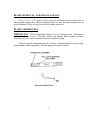
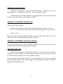
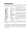
OPERATOR’ SMANUAL SDR 90, SDR65 Single Deck ROTARY ROLLER MOWER PROGRESSIVE TURF EQUIPMENT INC. 137 WEST WILLIAM STREET SEAFORTH, ONTARIO CANADA N0K 1WO PHONE: FAX: WATTS: 519-527-1080 519-527-2275 1-800-668-8873 SERIAL # ____________ Website: www.progressiveturfequip.com Email : [email protected] ISSUE DATE: AUGUST 2007 TABLE OF CONTENTS PAGE INTRODUCTION TOTHEOWNER ……………………………………………. . GENERALI NFORMATI ON ………………………………… WARRANTY ………………………………………………… SAFETY INSTRUCTIONS SPECIFICATIONS……………………………………………. . SAFETYDECALS ……………………………………… MAI NTENANCESAFETY …………………………………. . . 3 4 5 6 7 8 9 OPERATION OF THE MOWER DAI LYCHECKLI ST …………………………………………. HI TCHI NGMOWERTOTRACTOR …………………………. CONNECTI NGPTOSHAFTS ………………………………… ADJUSTING PTO LENGTH …………………………………. CUTTI NGHEI GHTADJ USTMENT …………………………. . TRANSPORTI NGMOWER …………………………………… GREASECOMPATI BI LI TY……………………………………. LUBRI CATI ON ………………………………………………… GEARBOXOI LLEVEL ………………………………………. . 10 11 11 12 13 14 15 16 17 MAINTENANCE MOWERBLADESERVI CI NG ………………………………. BLADEREMOVAL& I NSTALLATI ON …………………… BLADESHARPENI NG ………………………………………. SPI NDLEI NSPECTI ON ……………………………………… SPI NDLEASSEMBLYREMOVAL …………………………. SPI NDLEASSEMBLYI NSTALLATI ON …………………… ASSEMBLYOFSPI NDLES …………………………………. “ V”BELTADJ USTMENT …………………………………… “ V”BELTTENSI ON …………………………………………. TROUBLESHOOTI NG ……………………………………… 2 18 19 19 20 20 20 21 22 22 23 TO THE OWNER: Before you operate this mower, study this manual carefully. It has been prepared to help you do a better and safer job of maintaining your mower. Use only genuine Progressive Turf Equipment Inc. replacement parts. Substitute parts will void the warranty and may not meet the standards required for safe and satisfactory operation of this equipment. Blades are especially important. Their manufacturing process is a very exacting one and only a handful of blade producers are capable of this process. Always insist on purchasing and using OEM blades for your own protection and that of your employees. ATTENTION - This safety symbol means your personal safety is involved. Be sure to observe and follow these instructions. DANGER - An extreme intrinsic hazard exists which would result in high probability of death or serious injury if proper precautions are not taken. WARNING - A hazard exists which can result in injury or death if proper precautions are not taken. CAUTION - A reminder about safety practices, or directs attention to unsafe practices, which could result in personal injury if proper precautions are not taken. 3 GENERAL INFORMATION: The purpose of this manual is to assist the operator in maintaining and operating Progressive Turf Equipment mowers. Read it carefully. It furnishes information and instructions that will help you achieve years of dependable performance. Some information may be general in nature due to unknown and varying conditions. However, through experience and these instructions, you should be able to develop operating procedures suitable to your particular situation. Throughout this manual, references are made to right and left directions. These are determined by standing at the rear of the equipment and facing the direction of forward travel. Blade rotation is counter-clockwise as viewed from the top of the mower. For quick reference, record the following information. MODEL: ___________________________ DATE PURCHASED: ___________________________ SERIAL NUMBER: ___________________________ For additional information, assistance during assembly, or operation of this mower, contact the dealer from whom the machine was purchased, or call Progressive Turf Equipment Inc. PHONE: 519-527-1080 1-800-668-8873 4 FAX: 519-527-2275 WARRANTY POLICY (To validate warranty, the Delivery and Warranty Registration form must be completely filled out & mailed to Progressive Turf Equipment Inc.) Progressive Turf Equipment Inc. warrants each new product to be free of defects in material and workmanship to the original purchaser. Warranty will be applicable, from the original date of purchase. Pro-Flex 120, TD65-2, TD65, TD92, Pro-Max 36, TDR-22, TDR-15, SDR-65, SDR-90 FOR ALL APPLICATIONS - 12 MONTHS This warranty coverage supersedes all written warranties, effective February 12/02. This warranty will not cover any components which, in the opinion of the company, have been subjected to negligent use, alteration, or accident, or if parts supplied by others have been used in repairs of any product manufactured by Progressive Turf Equipment Inc. Our obligation, in the event that any Progressive Turf Equipment Inc. product warranted, shall become defective or fail, will be limited to repairing or replacing free of charge, or provide labour and materials for the repair of, any defective part, subject to company approval. All defective parts must be retained for 60 days after applying for warranty. Any parts to be returned to Progressive Turf Equipment Inc. for inspection will be issued an RGA number and must be returned within 14 days, transportation charges prepaid. This warranty will not provide for service calls to customer location or for transportation of equipment to dealer location if such servicing is required. The sole liability of Progressive Turf Equipment Inc. under this warranty or any implied warranty, shall be limited as set forth herein. The customer agrees that Progressive Turf shall not in any event be obligated to reimburse, or pay the customer for any expense, loss or any direct, incidental or consequential damages to any person or property for any reason, or caused by reason of Progressive Turf Equipment Inc., negligence, or otherwise in connection with the sale, delivery, installation, training or use of the equipment. The customer shall indemnify and hold Progressive Turf Equipment Inc. harmless against all such liability. This warranty is not subject to change or modification by anyone, including dealers, and no one is authorized to make any representation on behalf of Progressive Turf Equipment Inc. 5 SAFETY WORK SAFELY ---- FOLLOW THESE RULES Instructions given with this symbol are for personal safety. Be sure you and your workers follow them. A CAREFUL OPERATOR IS THE BEST INSURANCE AGAINST AN ACCIDENT BEFORE HANDLING ANY EQUIPMENT READ THEOPERATOR’ S MANUAL. To avoid accident or injury, do not allow anyone to operate this equipment without proper instructions. Any person who operates this equipment must be instructed in and be capable of the safe operation of the unit. Know your controls and how to stop tractor engine, and mower quickly in an emergency. OPERATING SAFELY: Shift tractor into neutral and disengage power take-off before starting tractor. Never allow riders on tractor or equipment. Use extreme care when operating on uneven terrain. Immediately stop mower and shut off tractor upon striking any object. Inspect mower and repair any damage before you continue mowing. Always turn off tractor before making any adjustments to mower, if operator has to dismount tractor. If mower becomes clogged, disengage power to mower and turn off tractor before dismounting. Always disengage PTO and be sure driveline has stopped rotating before raising decks into transport position. Always obey all local and state regulations when operating on public roadways and highways. Reduce speed while operating during wet conditions on slopes, especially when making sharp turns. 6 SDR MOWER SPECIFICATIONS Cutting Dimensions Deck Dimensions Recommended HP Weight Speeds Blades Spindles Cutting height Deck Drive Blade Support Deck Construction Rollers Belt Adjustment P.T.O. Shaft Lift Link SDR-65 65 ” Width Length 72 ” 5 1” 25 hp* SDR-90 90 ” Depth 7” Width Length 97 ” 52” 35 hp* Depth 7” 975 LBS 1380 LBS TRACTOR PTO –540 rpm TRACTOR PTO –540 rpm Blades –3040 rpm Blades –2890 rpm Blade tip speed - 18 287 rpm Blade tip speed –18 300 fpm 3-2 3”Bl a de s 4-2 4”Bl a de s 5/ 16”x21/ 2”he a tt r e a t e da l l oys t e e lbl a de s 3 Spindles, 30 mm 4 spindles, 35 mm Supported by 2 grease-able ball bearings which are housed in a precision machined hub. I nf i ni t es e t t i ngsf r om1/ 2”t o4” PTO shaft to r i g hta ngl ege a rboxdr i vi n g“ B”s e c t i o nb e l t st o heavy duty spindles. 3/ 4”x1 / 2”x8”l o ngba rwe l de dt os pi n dl ea ndma c hi ne df or ba l a n c e .Two1/ 2 ”bo l t sho l dbl a der i gi dt op r ov i deac l e a nl e v e l cut A single piece of 3/ 16”s t e e lpl a t ef or me da ndwe l de dwi t h supporting members at high stress areas to achieve maximum structural strength. 6”di a me t e rwi t h0. 1 88”wa l lt hi c kne s s ,s u pp or t e db y11/ 4”t wo bolt ductile flange bearings. Easily made by loosening hold down bolts and adjusting tap bolt to desired belt tension. Telescoping category #4 agricultural PTO drive shaft, with proper safety shields, 13/ 8 ”–6 spline quick disconnect yokes on both ends with ring lock collars Category 1 *May require weights on the front of the tractor 7 OBEY THESE SAFETY DECALS: If decals become faded, damaged, or lost, replace immediately. Item 2 ITEM 1 ITEM 3 ITEM 4 ITEM 5 ITEM 6 8 MAINTENANCE SAFETY: Never work on mower without safety locks in place, if decks are in raised position. Keep tractor and mower in good operating condition and all safety devices in place. Frequently check blade mounting bolts for tightness. Periodically check to ensure all bolts are tight and that all nuts, screws and cotter pins are properly installed to ensure that the mower is in a safe condition. PROPER TORQUE FOR FASTENERS: The chart lists the correct tightening torque for fasteners on Progressive Turf Equipment mowers. When bolts are to be tightened or replaced, refer to this chart to determine the proper torque except when specific torque values are assigned in the manual. Only SAE grade 5 fasteners are to be used in the assembly of this machine, or as otherwise specified in this manual. Bolt Head Markings SAE Grade 2 (No Dashes) SAE Grade 5 SAE Grade 8 (3 Dashes) (6 Dashes) Recommended Torque in Foot Pounds (Newton-Meters) Bolt Diameter (in.) 5/16 3/8 7/16 ½ 9/16 5/8 ¾ 7/8 1 1”L. H.Spi ndl eNu t SAE Grade 5 21 (28) 38 (52) 55 (75) 85 (115) 125 (170) 175 (240) 300 (410) 450 (610) 680 (925) 60 (82) 9 OPERATING THE MOWER: A careful and knowledgeable operator is the best insurance against an accident. Allow no riders on any equipment. If tractor is equipped with R.O.P.S., use the seat belt for maximum protection. Make sure that everyone is clear of the tractor and mower before starting the engine or operating. DAILY CHECK LIST: 1. Always wear relatively tight and belted clothing to avoid entanglement in moving parts. Wear sturdy, rough soled work shoes. Never operate tractor or implements in bare feet, sandals or sneakers. 2. Check that mower is properly and securely attached to tractor with a safety chain. 3. Ensure all safety shielding is properly installed and check that all nuts and bolts are secure and pins are properly cotter-pinned. 4. Check condition of blades and security of attachment. 5. Ensure mower is properly mounted, adjusted and in good operating condition. 6. Clear area of stones, branches or other debris that might be thrown causing injury or damage. 7. Never permit any person other than the operator to ride or board the tractor at any time. 8. Check that all lubrication points with grease fittings have been lubricated as per schedule. 9. Check the gearbox for proper amount of gear oil. Mower must be on level surface when this is done. 10 HITCHING MOWER TO TRACTOR: For proper mower operation and maximum PTO life, the mower and PTO driveline must be setup correctly. a) Lower three point hitch arms on tractor and align them with the lower hitch links on both ends of the hitch assembly. Insert a 7/ 8”p i nt os ecure links to lower tractor arms. b) Adjust tractor top link length to match distance between top link of mower and t r a c t o rt opl i n kmou nt .At t a c hwi t h7/ 8”pi n. c) Raise and lower mower to ensure that it does not come into contact with the tractor. The links should operate smoothly and should not bind. Note that the SDR90 will require front bumper weights. CONNECTING THE PTO SHAFT: a) Ensure that the tractor engine is shut off and the parking brake is locked. b) Holding the PTO against the end of the tractor PTO shaft, rotate the tractor PTO by hand until the shaft slides on slightly. c) Slide the locking collar on the PTO backwards, releasing the locking mechanism. Hold and slide the PTO on. d) Release the locking ring and pull the PTO shaft backwards until the locking mechanism snaps into place. e) Push the shaft forward and backwards to ensure that this is securely locked in place. f) NOTE: If mower is being used on another tractor, it is necessary to ensure that the overall length of the PTO is correct. Check and adjusted per the steps outlined above CAUTION - If the PTO shaft comes off during operation, it may cause personal injury and damage to the PTO shaft and tractor PTO. When checking, make sure the locking collar is locked, and that the shaft is not just jammed against the end of the tractor PTO shaft. 11 Adjusting the PTO shaft to the correct length IMPORTANT: 1. When checking driveline PTO shaft minimum length, it is necessary to a l i g na ndl e v e lt het r a c t or ’ sPTOs ha f twi t ht heg e a r b oxs ha f toft h emowe r . Measure the shortest distance possible between the tractor PTO shaft and the gearbox shaft of the mower. The lower links on the 3 point hitch must be hanging downward to obtain the shortest length (see diagram 1). lower links Diagram 1 2. Shorten the driveline PTO shaft as follows: a. Make sure the tractor PTO shaft and the mower PTO shaft are level with each other. b. Separate the two driveline shaft halves and connect one half to the tractor PTO shaft and the other half to the mower gearbox shaft. c. Hold driveline shaft halves side by side to determine if they are too long. The s hi e l dsone a c hha l fs houl de nda p pr oxi ma t e l y3”f r omt heun i v e r s a lj o i n ts hi e l d. Me a s ur e3”ba c kf r omt heu ni ve r s a lj oi nts hi e l d( di me ns i onXonDi a g r a m2)a n d mark that location on the inner and outer shields. d. Cutof ft heo ut e rs h i e l da tdi me n s i o n‘ A’ .Me a s u r ed i me ns i on‘ A’f r o mt hee n dof the outer shaft and cut the same amount off of the outer shaft. Cut off the inner s hi e l da tdi me ns i on‘ B’ .Me a s ur edi me ns i o n‘ B’f r omt h ee ndoft hei nne rs haft and cut the same amount off of the inner shaft. e. Remove all burrs from shafts. Keep shaft ends square not rounded off. Clean all filings from drive shield tubes. f. Once driveline has been reassembled, check to make sure the driveline does not bottom out in the shortest position. A X Tractor PTO Mower PTO B X Diagram 2 12 CUTTING HEIGHT ADJUSTMENT: There are four height adjusters per mowing deck. Each adjuster (located in each corner of the deck) must be adjusted to the same height to ensure a smooth even cut. A wrench for this purpose is provided. In addition, each deck must be adjusted the same so that a level cut is obtained across the whole cutting width of the mower. Mowe rc ut t i ngh e i ghta d j us t me nti sma debyt ur ni nga5/ 8”n uton top of an acme treaded rod which makes up the height adjuster. A washer under the nut indicates the height against the decal. There are an infinite number of a dj us t me nt sa va i l a bl ef r om ½”t o4” .Mo vi ngt hea dj us t e rupa n dd ownmove sa side rail that mounts the front and rear rollers. Before attempting to make height adjustments, the locking bolt on the side rail adjacent to the adjuster must be loosened. When the desired adjustment is made, be sure to tighten the locking bolt and adjuster jamb nut to maintain the adjusted height. Always adjust so that the back of the deck cuts slightly higher than the front. Doing this provides a better cut and requires less horsepower. SDR-90 HEIGHT ADJUSTER Height indicator washer Height scale Jamb nut Slide rail lock bolt 13 TRANSPORTING MOWERS: CAUTION - When traveling on public roadways, use flashing amber lights and S.M.V. emblem on rear of mower to provide greater visibility to other traffic. WARNING - When towing this mower the following information concerning road speed should be strictly adhered to. WEIGHT OF TOWING VEHICLE 4500# or more Less than 4500# but More than 2300# Less than 2300# MAXIMUM ALLOWABLE ROAD SPEED Up to 20 mph (32km/h) Up to 10 mph (16km/h) DO NOT TOW CAUTION - Always have safety chain attached to towing vehicle. POWER TAKE-OFF: CAUTION - Keep all safety shields in place. CAUTION - When operating the power take-off, be sure the tractor shield is always in place, covering the exposed power take-off shaft. WARNING - Before dismounting from the tractor, stop the power take-off, put tractor in neutral, set brakes in lock position and shut off engine. CAUTION - When ready to engage PTO shaft, be sure engine RPM is at idle speed. Engaging PTO at full throttle will cause high shock loads to driveline, with the potential for future failure. NOTE: Do not exceed the recommended PTO speed of 540 RPM. 14 An Important Word On Grease Compatibility What Grease Is: -Grease is essentially a distilled petroleum product in the form of mineral oil (or a synthetic) which has a thickening agent such as lithium, calcium, barium, sodium, or aluminum. -Many of the thickeners will work for similar situations, but when mixing greases with different thickeners, one must review compatibility. Grease incompatibility will actually decrease the lubrication ability of the grease, and cause premature part failure. -There may be other additives in the grease that impart special properties. These properties ma yb e“ h i g ht e mp e r a t u r e ” , “ e x t r e mepr e s s ur e ” ,e t c . What We Use: - Our bearing supplier uses Shell Alvania 2 - Progressive uses Texaco Multifak EP 2 - EP means extreme pressure - Both greases have: - A mineral oil base - A lithium thickener - The mineral oil has a NLGI Grade 2 - Both greases are compatible with each other Note: -If a thickener other than lithium is used, the existing grease will be contaminated and the lubrication properties may be lost. -If a synthetic base oil is used rather than a mineral base oil, the grease will again be contaminated and the lubrication properties may be lost -Molybdenum Disulfide (Moly) is an additive used in slow moving, extreme load a p pl i c a t i ons .Thep a r t i c l e si nt he“ Mol y ”wi l la c t u a l l yincrease bearing wear in a mower spindle. Our grease does not contain Moly. -The blade spindle temperature should never go above 120°F if properly greased; we do not recommend high temperature grease. Agr e a s ewi t ht h e s ef e a t ur e si sc ons i de r e dt obea“ Ge ne r a lPu r pos eGr e a s e ” .Us eona l l grease point locations on your Progressive Mower. Our Recommendation for Grease Compatibility: The grease you use for the blade spindle assemblies must have these properties: NLGI grade 2 Lithium thickener (NOT LITHIUM COMPLEX OR LITHIUM 12-HYDROXY) Kinematic Viscosity at 40°C is no greater than 190 cSt Dropping Point Less than 400° F General Purpose Grease, Not Heavy Duty No MOLY (molybdenum disulphide) additives in the grease No synthetic grease No High Temperature Grease Check the properties of the grease you wish to use with your supplier prior to use. 15 LUBRICATION: A properly maintained lubrication schedule will provide a smooth running machine for many years. The following information shows and describes where all lubrication points are located. DECK Spindles* (See Manual) *As Required P.T.O. SHAFTS Main Input*(See Below) Pull Apart Sliding Tubes once per week and lubricate *As Required CHECK FOR PROPER OIL LEVEL IN GEARBOXES DAILY GREASING SCHEDULE & LOCATION BLADE SPINDLE GREASING: The top bearing on all spindle assemblies has a shield only. This allows grease to exit and relieves any pressure build up inside spindle housing, when greasing. Greasing of blade spindles should continue until grease can be seen exiting between the top bearing and the bottom of hub on pulley. Some working conditions will require this operation to take place every 4 to 5 running hours because of hot working areas. Cooler working areas will only require greasing every 8 to 10 hours. A proper greasing schedule can only be determined by operator, depending on working conditions in your particular area. 16 GEARBOX OIL LEVEL: IMPORTANT! DO NOT OVERFILL! MOWER MUST BE LEVEL WHEN CHECKING GEARBOX OIL LEVEL DECK GEARBOX: Gearboxes all have an oil level plug located on the side of the gearbox. Oil should reach the bottom of this hole. If oil level is low, add oil through top plug hole of casing until oil just starts to flow out of side oil level hole. Replace and tighten plugs. Use 80W90-gear oil or equivalent. Filler Plug Level Plug 17 MAINTENANCE: WARNING - Turn tractor engine off before performing any maintenance. CAUTION - Always use personal protection devices such as eye and ear protectors when performing maintenance functions. WARNING - When completing a maintenance or service function, make sure all safety shields are installed before placing mower in service. BLADE SERVICING: WARNING - Be sure safety locks are in place when working on decks in the raised position. The tractor hydraulic system could fail, causing decks to fall and crush anything under them. Do not handle mower blades with bare hands. Careless or improper handling may result in serious injury. Inspect blades before each use to determine that they are mounted tightly and are in good condition. Replace any blade that is bent, excessively nicked, worn or has any other damage. Small nicks can be ground out when sharpening. WARNING - Only original equipment blades should be used when replacing worn out mower blades. They are made of special steel alloys and subjected to rigid heat-treat and inspection requirements. Substitute blades may not meet these rigid specifications and MAY BE DANGEROUS. 18 BLADE REMOVAL AND INSTALLATION: Two, 1/ 2”X 1 3/ 4”gr a de5b ol t swi t hl oc kwashers and nuts hold blade to blade spindle support bar. When changing blades, be sure that these fasteners are in good condition so they will not come loose during operation. BLADE SHARPENING: IMPORTANT - When sharpening blades be sure to balance them. Unbalanced blades will cause excessive vibration, which can damage blade spindle bearings. Vibration may also cause structural cracks in spindle housing. Follow original sharpening pattern as shown. Sharpen blade to a razor edge. Protect hands when sharpening. Do not sharpen backside of blade. BLADE SHARPENING 19 SPINDLE INSPECTION: Spindles are equipped with two roller ball bearings. Adjustment is set by t i gh t e n i n gt he1”l e f tha ndnu tt o60f t -lbs. torque for proper setting. Periodically inspect blade spindles by grasping blade, and moving from side to side. If any free play is noted, replace or repair. SPINDLE ASSEMBLY REMOVAL: Remove blade from spindle. Remove belt shield. Loosen 4 bolts that hold gearbox to mount. Loosen 1/2”x 3 1/2”t a pb ol t sa nds l i deg e a r b oxt owa r df r on tu nt i lbe l ti se a s yt or e mo ve . Remove belt. Remove 4 bolts attaching spindle assembly to mower frame and remove as a unit, since pulley will come out through the hole in the deck. SPINDLE ASSEMBLY INSTALLATION: Reverse above procedure. Be sure spindle mounting area of deck is clean of any foreign material before attaching spindle assembly. SPINDLE REPAIR: Spindle repair requires special skills and tools. If your shop is not properly equipped or your mechanics are not properly trained in this type of repair, you may be time and money ahead to use a new spindle assembly. Remove pulley from spindle assembly. Place assembly in press and force spindle down through housing. Once pressed apart, replace bearings, as removal will have damaged bearings internally. 20 ASSEMBLY OF SPINDLE: Only use a press that has the ram and bed 100% square to each other. If bearings are not square in housing, bearings will wear out prematurely. Press on outer race when inserting into hub and press on inner race when installing on spindle. If bearings are being changed, be sure to check bearing spacer for wear. If wear is noticed, insert new spacer. This is critical because if spacer is short by only . 01 0” ,t het opb e a r i n gwi l ls t a r tt obi nd and will result in premature failure. Bearing with seal and shield combination will be pressed into the blade side of the hub first with the seal side facing out. Next, set spindle on press bed, install dirt shield and shim first (as per diagram) set hub, bearing end down, onto spindle. You must use a tube (Note: both ends must be square) which will slide over spindle and press on inner race of bearing, until seated against shim. Insert bearing spacer tube with hole end up. Set remaining bearing with shield side up, open side on first, onto spindle. Press on inner race (this bearing will be a loose fit in the hub so it will seat itself properly). When all parts have been installed on spindle, torque left hand nut to 60 ftlbs. and then tighten set screws in pulley. Once the assembly is complete, fill with quality grease until it can be seen exiting the top bearing. Rotate the housing six revolutions by hand so the bearings will have the grease worked into them, and at the same time check for free movement. The assembly is now ready for installation into the mower deck. 21 “V”BELTADJUSTMENT: Begin by loosening 4 bolts at the base of the gearbox. Adjusting long threaded bolt slides the gearbox back, tightening belt. After proper tension is a c hi e ve d ,t i gh t e n4bol t sa tba s eofge a r bo x.Yo uma yha vet opl a c ea½”nu tun de r the head of the long threaded bolt to increase your adjustment length. When changing belts, removal of grease fitting from the top of the center spindle will make installation easier. Be sure belts run in proper groove. “V”BELTTENSI ON: Proper belt tensioning is a fundamental factor in the successful V-belt operation. Lack of tension will cause slippage, and too much tension will cause excessive belt stretch as well as damage to the drive components, such as bearings and shafts. Therefore, to ensure proper belt tension, the following procedure is recommended. CHECKING BELT TENSION At the mid-point of the span, apply a deflection force with a spring scale in t hedi r e c t i onpe r pe n di c ul a rt ot hes pa nunt i lt hebe l ti sde f l e c t e dt he3/ 8” . The recommended force to deflect the belt is a minimum of 4.9 lbs. to a maximum of 7.3 lbs. Thef i r s t24t o48h our sofope r a t i o ni st hebe l t“ r uni n”pe r i od.Toe ns ur e satisfactory belt performance, belt tension should be checked during this time period. 22 TROUBLE SHOOTING: PROBLEM CAUSE REMEDY Belt slippage Lack of tension oily drive conditions Increase tension Clean up drive Rapid belt wear Belt slippage belt not in proper groove Increase tension Place in proper groove Belt squeal Belt slippage Increase tension Over-heated bearings Belt slippage excessive drive tension Increase Tension Tension drive properly Input shaft does not collapse easily on turning. Lack of grease at Remove driveshaft and intermediate location of pull apart. Grease drive shaft splines. Grease every 8 hours. Premature spindle bearing failure. Lack of lubrication or grease is contaminated 23 See grease information and ensure grease being used is compatible. Grease per instructions