1
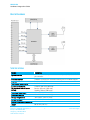
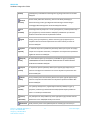
SDC-EC15N Hardware Integration Guide REGULATORY Note: Operation in the 5150-5250 MHz band is limited to indoor use only in some regulatory domains. Certified Antennas The SDC-EC15N provides two MMCX type antenna connectors to support transmit and receive diversity and 2 x 2 MIMO support. For single antenna, non-diversity applications, OEMs are advised to use the Main (not Aux) antenna connector on the xxxx side of the radio (see Mechanical Specifications above) and should disable transmit and receive diversity from the Global tab of the Summit Client Utility (SCU) software utility. The SDC-EC15N has been tested to the same regulatory standards as the SDC-PE15N. These tests were conducted with the following antennas: Summit SDC-CF22G Antenna (click for datasheet) Form Factor: Chip Antenna on PCB Type: Dipole Maximum 2.4 GHz Gain: 0 dBi Cisco AIR-ANT 4941 (click for datasheet) Form Factor: Whip Type: Dipole Maximum 2.4 GHz Gain: 2.2 dBi Tested and Certified 2.4 GHz Transmit Power: 90% of maximum setting Radiall Larson Dipole (click for datasheet) Form Factor: Whip Type: Dipole Maximum 2.4 GHz Gain: 1.6 dBi (not used during testing) Maximum 5 GHz Gain: 5 dBi HUBER+SUHNER (click for datasheet) Form Factor: Whip Type: Monopole Maximum 2.4 GHz Gain: 3 dBi Maximum 5 GHz Gain: 6.5 dBi Tested and Certified 2.4 GHz Transmit Power: 95% of maximum setting Tested and Certified 5 GHz Transmit Power: 100% of maximum setting Note: The formal test reports for the SDC-PE15N show that transmit power was decreased to less than 100% on 2.4 GHz edge channels. Summit has made these transmit power reductions in firmware for the edge channels. Integrators do not need to reduce transmit power on a channel-by-channel basis to account for band edge regulations. Americas: +1-800-492-2320 Option 3 Europe: +44-1628-858-940 Hong Kong: +852 2923 0610 www.lairdtech.com/wi-fi 12 Laird Technologies