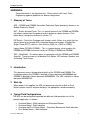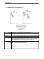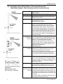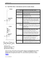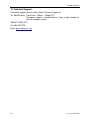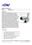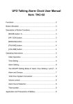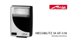
1
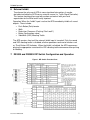
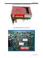
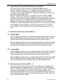
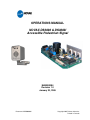
OPERATIONS MANUAL
NOVAX DS3000 & DS3000i
Accessible Pedestrian Signal
MAN000094
Revision 1.0
January 30, 2006
Document: MAN000094
Copyright 2005: Novax Industries
Printed In Canada
PROPRIETARY NOTICE 2006
NOVAX INDUSTRIES CORPORATION
This document is the intellectual property of Novax Industries Corporation and is
not to be released to any third party in any form. This document may contain
sensitive conceptual ideas or methodologies that could result in the loss of
Novax’s competitive advantage if revealed to an outside party.
Contact
NOVAX INDUSTRIES CORPORATION
658 Derwent Way,
New Westminster, BC
Canada, V3M 5P8
Phone: (604) 525-5644
Fax: (604) 525-2739
Internet: http://www.novax.com
E-Mail: [email protected]
DISTRIBUTOR
Table of Contents
WARNINGS: ................................................................................................................... 1
1
Glossary of Terms.................................................................................................. 1
2
Introduction ............................................................................................................ 1
3
Start-Up ................................................................................................................... 1
4
Typical Field Configurations ................................................................................. 1
4.1
Overhead Mount - Walk Indication and Directional Guidance........................... 2
4.2
Overhead Mount - Walk Indication only ............................................................ 3
4.3
Overhead and Push Button Mount - Directional Beacon with Push Button
Speaker - Walk Indication and Pole Location Sounds ................................................. 4
4.4
5
Push Button Mount - Walk Indication and Pole Location Sounds ..................... 5
Basic Operation...................................................................................................... 6
5.1
DS3000 Mode only: Push Button Re-service of Walk Message........................ 6
5.2
DS3000 Mode only: Short Button Press Mode.................................................. 6
5.3
DS3000 Mode only: Long Button Press Mode .................................................. 6
6
External Inhibit ....................................................................................................... 7
7
DS3000 and DS3000i DIP Switch Configuration and Operation......................... 7
Sound Selection (Switch DSW1-1, -2, -3, -4)............................................................... 8
Sound Selection (Switch DSW1-1, -2, -3, -4)............................................................... 9
7.1
Legacy Mode: DS100 and DS2000 Mode (Switch DSW1-6) .......................... 10
7.2
Sound w/o Button Press (Switch DSW1-5) ..................................................... 10
7.3
Walk Repeat Select (Switch DSW2-1, -2)....................................................... 10
7.4
Maximum Walk Timer (Switch DSW2-6, -7, -8)............................................... 11
7.5
Button Actuated Timer (Switch DSW2-3, -4, -5).............................................. 12
7.6
Button Actuated Timer - Operational Details................................................... 13
8
Visual Button Press Confirmation ...................................................................... 14
9
Vibrating Tactile ................................................................................................... 15
9.1
VB2 (VibraWalk2) ........................................................................................... 15
9.2
VB1 (VibraWalk1) ........................................................................................... 15
Document: MAN000094
i
Table of Contents
10 DS3000 Set-Up...................................................................................................... 16
10.1
Push Button (Pole) Locator Sound.................................................................. 16
10.2
Walk & Pedestrian Clearance Sound.............................................................. 16
10.3
Dynamic Proportional Volume Control ............................................................ 16
10.4
Importance of Automatic Volume Control ....................................................... 17
10.5
Volume Calibration.......................................................................................... 18
10.6
Testing the Push Button Locator Sound Level................................................ 19
10.7
Testing the Overhead Beacon Sound Level ................................................... 20
11 Fault Conditions and Responses ....................................................................... 20
11.1
Absence of Signal: .......................................................................................... 20
11.2
Presence of both WALK and DON’T WALK:................................................... 20
11.3
Constant Push Button Call Fault ..................................................................... 21
12 Troubleshooting................................................................................................... 21
13 Technical Support................................................................................................ 26
List of Tables
Table 1: Default Sound Select Table Note 2 ....................................................................... 9
Table 2: Custom Sound Select Switch example 2........................................................... 9
Table 3: Walk Repeat Selection .................................................................................... 11
Table 4: Max Walk Timer Settings................................................................................. 11
Table 5: Button Actuated Timer Hold Settings (BAT) .................................................... 13
Table 6: Push Button (Pole) Locator Sound Adjustment Cases .................................... 19
Table 7: Overhead Beacon Sound Adjustment Cases .................................................. 20
List of Figures
Figure 1. DIP Switch Function Chart ............................................................................... 7
Figure 2: DS3000 DIP Switch Location (Bottom View).................................................... 8
Figure 3: DS3000i DIP Switch Location (Top View) ........................................................ 8
Figure 5 DS3000 DSW1 & 2 Switch Locations.............................................................. 22
Figure 6 DS3000i Fuses, Inhibit Switch, and DSW1 & DSW2 Switches location .......... 23
ii
Document: MAN000094
Table of Contents
Document: MAN000094
iii
DS3000 Operation
WARNINGS:
Setup Information is for reference only. Please consult with Local Traffic
Engineering approval guidelines for device configuration
1 Glossary of Terms
APS – DS3000 and DS3000i Accessible Pedestrian Signal (previously known as an
Audible Pedestrian Signal)
BAT – Button Actuated Timer. This is a special feature of the DS3000 and DS3000i
that allows monitoring of the pedestrian push button for special features. Push
button delay settings can be found in section 7.5
DIP Switch – Dual Inline Package multi-selector switch. Refers to a switch that has
the pin format of a standard 8-Pin integrated device and includes 8 Single-PoleSingle-Throw (SPST) switches. Also called as DSW (i.e.; DSW1 or DSW2).
Legacy Mode (DS100 & DS2000) – This is a special feature, which enables the
DS3000 and DS3000i to function similar to DS100 or DS2000 and DS2000i.
VB2 – VibraWalk2. This device works in conjunction with the DS3000 and DS3000i
(internal). The device consists of durable Push Button, LED indicator, Speaker and
a Vibrating Tactile Arrow.
2 Introduction
This document covers the operational details of the DS3000 and DS3000i. The
installation guide of the DS3000 is detailed in Novax document MAN000089 and
DS3000i is detailed in Novax document MAN000090. The VB2 is detailed in Novax
document MAN000130.
3 Start-Up
When power is first applied, the APS unit determines whether a Walk or Push
Button Locator sound is required and plays the appropriate sound immediately.
4 Typical Field Configurations
The APS can be configured to provide four different field operations to suit the
required application, as follows:
Overhead Mount - Walk Indication and Directional Beacon
Overhead Mount - Walk Indication
Overhead and Push Button Mount – Directional Beacon with Walk Indication
Push Button Mount – Walk Indication
Document: MAN000094
1
DS3000 Operation
The diagrams and operational description below describe the selection of the
configuration for numerous applications and provide the safest pedestrian signaling
service.
4.1
Overhead Mount - Walk Indication and Directional Guidance
Purpose Walk indication and directional guidance
Mode Legacy Mode (DSW1-6 + 1 Directional sound)
Walk Sounds Peep, Cuckoo, Voice, Tok, Melody (4 tone)
Ped. Clear Sounds Ped Clearance Push Button (Pole) Locator (loud), Melody (3 tone) or
Silent
WALK Indication The Walk sound is played through the overhead speaker only when the
Walk signal is active to indicate to the pedestrian when it is their time to
start the crossing and provides directional guidance. The sound should be
detectible at two-thirds of the crossing distance from the far side.
PED. CLEAR The Ped Clearance Push Button (or Pole) Locator sound (if programmed
Indication to the Ped Clearance) is played through the overhead speaker only to
provide additional guidance to the pedestrian for locating the far side of
the crossing. The sound should be detectible at two-thirds of the crossing
distance from the far side.
DON'
T WALK No sound should be played through the overhead speaker at this time. If a
Indication Push Button location sound is required, please purchase the VibraWalk
unit or separate Push Button speaker.
2
Document: MAN000094
DS3000 Operation
4.2
Overhead Mount - Walk Indication only
Purpose Walk indication, Push Button location (no directional guidance)
Mode DS100 Mode (DSW1-6 + 1 Directional sound)
Walk Sounds Peep, Cuckoo, Voice, Tok, Melody (4 tone)
Ped. Clear Sounds Silent
WALK Indication: The Walk sound is played through the overhead speaker only when the Walk signal
is active to indicate to the pedestrian when it is their time to start the crossing. The
sound should be detectible at a distance of 2 to 4 meters from the pole.
PED. CLEAR Pedestrian Clearance Push Button (Pole) locator sound not programmed. No sound
Indication should be played through the speaker at this time.
DON'
T WALK No sound should be played through the overhead speaker at this time. If a Push
Indication Button location sound is required, please purchase the VibraWalk unit or separate
Push Button speaker.
Document: MAN000094
3
DS3000 Operation
4.3
Overhead and Push Button Mount - Directional Beacon with
Push Button Speaker - Walk Indication and Pole Location Sounds
Purpose Walk indication and directional guidance and Push
Button Location
Walk Sounds Peep, Cuckoo, Voice, Tok, Melody (4 tone)
Ped. Clear Sounds Ped Clearance Push Button (Pole) Locator (loud),
Melody (3 tone), Silent
Don’t Walk Sounds Push Button (Pole) locator sound,
Acknowledgement sound
VB2 vibrating tactile pulsing
WALK Indication The Walk sound is played through the Push Button
speaker and optionally through the overhead
speaker when the Walk signal is active to indicate
to the pedestrian when it is their time to start the
crossing and directional guidance. The overhead
speaker sound should be detectible at two-thirds of
the crossing distance from the far side. The Push
Button speaker sound should be detectible at 2-4
meters from the Push Button or to the building line.
VB2 tactile vibration
PEDESTRIAN The Ped Clearance Push Button (Pole) Locator
CLEARANCE sound (if programmed) is played through the Push
Indication Button speaker and optional through the overhead
speaker. The overhead speaker should be
detectible at two-thirds of the crossing distance
from the far side. The Push Button speaker sound
should be detectible at 2-4 meters from the Push
Button or to the building line.
VB2 tactile pulsing
DON'
T WALK The Push Button (Pole) locator sound is played
Indication through the Push Button speaker only at a soft
volume to provide location assistance to
pedestrians to locate the pole and push button. The
sound should be detectible at 2 to 4 meters from
the push button or to the building line whichever is
less.
Optional Sounds Button Press Acknowledge: If a pedestrian push
button is connected to the APS, setting the Button
Detect feature will allow playing a confirmation tone
or voice on button press. The sound should be
detectible at 1 meter.
Custom Features Alternating Beacon: Setting this feature allows an
alternating effect of opposing APS units to assist
with the directional finding of the far side crossing.
Directional Setting this feature will only permit the Overhead
Crossing Sound on Beacon Walk and Pedestrian Clearance sounds to
Demand be played to provide guidance to the pedestrian for
locating the far side of the crossing if the pedestrian
pushed and held the button for the set time (ex. 0 to
7 seconds).
The sound should be detectible at two-thirds of the
crossing distance from the far side.
4
Document: MAN000094
DS3000 Operation
4.4
Push Button Mount - Walk Indication and Pole Location Sounds
Purpose Walk indication and Push Button Location
Walk Sounds Peep, Cuckoo, Voice, Tok, Melody (4 tone)
Ped. Clear Sounds Ped Clearance Push Button (Pole) Locator (loud),
Melody (3 tone), Silent
Don’t Walk Sounds Push Button (Pole) locator sound,
Acknowledgement sound
VB2 vibrating tactile pulsing
WALK Indication The Walk sound is played through the Push Button
speaker when the Walk signal is active to indicate
to the pedestrian when it is their time to start the
crossing. The Walk sound should be detectible at
two-thirds of the crossing distance from the far side
VB2 tactile vibration
PEDESTRIAN The Ped Clearance Push Button (Pole) Locator
CLEARANCE sound (if programmed) is played through the Push
Indication Button speaker. The Ped Clearance sound should
be detectible at two-thirds of the crossing distance
from the far side.
VB2 tactile pulsing
DON'
T WALK The Push Button (Pole) locator sound is played
Indication through the Push Button speaker only at a soft
volume to provide location assistance to
pedestrians to locate the pole and push button. The
sound should be detectible at 2 to 4 meters from
the push button or to the building line whichever is
less.
Optional Sounds Button Press Acknowledge: If a pedestrian push
button is connected to the APS, then setting the
Button Detect feature will allow playing a
confirmation tone or voice on button press. The
sound should be detectible at 1 meter.
Custom Features Alternating Beacon: Setting this feature allows an
alternating effect of opposing APS units to assist
with the directional finding of the far side crossing.
There are many more features for this product, which are not detailed on these typical
field use scenarios. Please refer to Section 7 - DS3000 and DS3000i DIP Switch
Configuration and Operation for details. For further technical specifications contact
NOVAX.
Document: MAN000094
5
DS3000 Operation
5 Basic Operation
The APS has the following basic operations:
1. Play Push Button Locator sound during the Solid Don’t Walk at the Push
Button speaker only.
2. Play Walk sound during the walk signal at overhead speaker and optionally at
push button (pole) locator speaker.
3. Play the Pedestrian Clearance Sound (if programmed) during the Pedestrian
Clearance signal. If not programmed, play Push Button Locator sound (soft)
during Pedestrian Clearance signal at the Push Button speaker only.
Factors that can influence the basic operation are outlined in section 7.
5.1
DS3000 Mode only: Push Button Re-service of Walk Message
5.1.1 Pedestrian Clearance sound programmed
If the condition where the Max Walk Timer (Section. 7.4) has timed out the playing
of the Walk message and Pedestrian Clearance message started playing during
the Walk signal. A pedestrian button press while the Walk signal is still active will
cause the Walk message to re-play and the Max. Walk Timer to re-start. The
Pedestrian Clearance signal will stop the Walk message immediately.
5.1.2 Pedestrian Clearance sound not programmed
The condition where the Max Walk Timer (Section. 7.4) has timed out the playing
of the Walk message and Push Button (Pole) locator message started playing on
the push button speaker (if available) only during the Walk signal. A pedestrian
button press while the Walk signal is still active will temporarily stop Push Button
(Pole) locator sound and play Acknowledgement sound on the push button
speaker only (if available). The push button speaker resumes playing. The APS
will enable the Call Out circuit to automatically play the Walk and Pedestrian
Clearance message on the next walk signal.
5.2
DS3000 Mode only: Short Button Press Mode
If a pedestrian push button is used and the button is held down for less than the
set Button Hold Time (Section. 7.5). No special APS feature is selected. This will
cause the Walk and Pedestrian Clearance (if programmed) message to be played
through the Push Button (or VibraWalk) speaker only.
5.3
DS3000 Mode only: Long Button Press Mode
If the pedestrian push button is held down for a time either equal or greater than the
set Button Hold Time (Section. 7.5). The Special APS feature is selected. This will
cause the Walk and Pedestrian Clearance (if programmed) message to be played
through both the Push Button (or VibraWalk) speaker1 and Overhead Beacon
speaker.
1
6
Unless the Legacy Mode: DS100 and DS2000 Mode (Switch DSW1-6) is selected. Refer to section 7.1.
Document: MAN000094
DS3000 Operation
6 External Inhibit
To enhance the safe use of APS at some signalized intersections it may be
desirable to disable the APS from an external source (i.e. Traffic Signal Controller).
This feature should only be used with caution and council with your local
organization for the Blind and Visually Impaired.
Operation: When the “Inhibit” input is active the APS immediately inhibits all sound
outputs. These include:
•
•
•
•
•
Push Button (Pole) locator
Walk
Pedestrian Clearance (Flashing “Don’t walk”)
Button Confirmation sound
VibraWalk (VB2) Vibrating Tactile
The APS remains silent until the external inhibit input is turned off. Only the sound
and VB2 vibrating tactile is disabled; all other operations continue to function such
as “Push Button LED Indicator. When the Inhibit is disabled, the APS commences
playing the appropriate sound and the VB2 vibrating tactile commence either pulsing
or vibrating
7 DS3000 and DS3000i DIP Switch Configuration and Operation
Figure 1. DIP Switch Function Chart
Legacy Mode
Document: MAN000094
7
DS3000 Operation
Figure 2: DS3000 DIP Switch Location (Bottom View)
Figure 3: DS3000i DIP Switch Location (Top View)
8
Document: MAN000094
DS3000 Operation
Sound Selection (Switch DSW1-1, -2, -3, -4)
There are four independent switches, #1 to #4 on DSW1, to select one of the four
sound pairs: One Walk sound and one “Pedestrian Clearance” (if required) sound
per switch.
The default sound pairs provided are described by the label on the device and
determined at the time of order from NOVAX. Changes in these sound pairs can
be made by replacing the Sound Storage chip in the DS3000. Contact Novax for
further details.
Only one of the four sound pairs can be selected at one time. For safety, if none of
the sound switches are set or more than one switch is set then the APS shall
remain inhibited (Quiet) even when a walk or don’t walk sound is required.
Table 1: Default Sound Select Table
Sound Select (DSW1)
1
2
3
4
Walk Sound
Chirp
Cuckoo
Chirp
Cuckoo
Note 2
Pedestrian Clearance Sound
Silence
Silence
Loud Pole Locator
Loud Pole Locator
If the Pedestrian Clearance sound is blank, the APS will default to playing the
Push Button Locator sound on the Push Button speaker only, during the
Pedestrian Clearance signal.2
The factory default setting is #1 on, and the other three switches off.
Application Note:
If a custom voice message is used, and Walk Repeat Select is not set to auto
repeat (refer to Section 7.4), this is generally recorded in position #1. In voice
message applications, sound slot #2 is reserved for a custom sound that can be
played following the voice message providing the Walk signal is still active and the
Max Walk Timer (if used) has not timed out. This special message will be played
until the end of Walk or end of the Max Walk Timer. The pedestrian clearance
sound will then play until the end of the pedestrian clearance time.
Table 2: Custom Sound Select Switch example 2
Sound Select (DSW1)
1
2
3
4
2
Walk Sound
Voice
Tok sound (continuous)
Pedestrian Clearance Sound
Optional
This table identifies the current production version. Consult the label for programmed sounds.
Document: MAN000094
9
DS3000 Operation
7.1
Legacy Mode: DS100 and DS2000 Mode (Switch DSW1-6)
This option allows the APS to simulate DS100 and DS2000 functions.
When the “Sound w/o Button Press” is enabled, the APS simulates DS100
functions. APS will automatically play the Walk and Pedestrian Clearance
message on the overhead speaker only if the pedestrian button was not pressed
during Don’t Walk or Walk signal.
When the “Sound w/o Button Press” is disabled, the APS simulates DS2000
functions. APS will play the Walk and Pedestrian Clearance message on the
overhead speaker only if the pedestrian button was pressed down for a time either
equal or greater than the set Button Hold Time during the Don’t Walk signal.
Pedestrian call (button pressed) during the Walk signal will either continue playing
the Walk message and remember the pedestrian call on the next cycle or play the
acknowledgement sound (Walk message not playing) and call out for another
cycle and play the Walk and Pedestrian Clearance (if programmed) on the next
cycle.
7.2
Sound w/o Button Press (Switch DSW1-5)
7.2.1 DS3000 Mode:
When disabled, if no button press was detected during the Don’t Walk and/or Walk
signal the DS3000 will continue playing the Push Button (Pole) locator sound on
the push button speaker only during the Walk and Ped Clearance signal
When enabled, if no button press was detected during the Don’t Walk and/or Walk
signal the DS3000 will play the Walk and Ped Clearance (if programmed) sound
on the push button speaker only during the Walk and Ped Clearance signal.
7.2.2 Legacy Mode:
When disabled: If no button press was detected during the Don’t Walk and/or Walk
signal the DS3000 will continue playing the Push Button (Pole) locator sound on
the push button speaker only during the Walk and Ped Clearance signal
When enabled: If no button press was detected during the Don’t Walk and/or Walk
signal the DS3000 will play the Walk and Ped Clearance (if programmed) sound
on the overhead speaker only during the Walk and Ped Clearance signal.
7.3
10
Walk Repeat Select (Switch DSW2-1, -2)
These two switches allow selection of how the main Walk sound is played. For
standard continuously repeating sounds (i.e.; Chirp, Cuckoo, Tok, Melody) both
switches should be turned off. For voice or custom Walk messages, the number of
times the message (play on the Push Button (Pole) locator speaker only) is
repeated during the Walk signal can be set, per the table below. Please note that
in any setting, the Walk message will terminate playing once the Walk signal turns
off or the Max Walk Timer expires.
Document: MAN000094
DS3000 Operation
Table 3: Walk Repeat Selection
DSW2 - 2
DSW2 - 1
Off
Off
Off
On
On
Off
On
On
Condition
Auto-Repeat Walk 1 sound until Walk signal has terminated or the Max Walk
Sound Timer has expired, whichever occurs first.
Play Walk 1 sound ONCE (on Push Button (Pole locator speaker only), then
Walk 2 sound until Walk signal has terminated or the Max Walk Sound Timer
has expired, whichever occurs first.
Play Walk 1 sound TWICE (on Push Button (Pole locator speaker only), then
Walk 2 sound until Walk signal has terminated or the Max Walk Sound Timer
has expired, whichever occurs first.
Play Walk 1 sound 3 TIMES (on Push Button (Pole locator speaker only),
then Walk 2 sound until Walk signal has terminated or the Max Walk Sound
Timer has expired, whichever occurs first.
In all cases, if the Max Walk Timer expires prior to the completion of the Walk
signal, the APS shall play the Pedestrian Clearance sound or Push Button locator
sound for the remaining Walk signal time, unless the push button is pressed (refer
to sec 5.1).
7.4
Maximum Walk Timer (Switch DSW2-6, -7, -8)
The Maximum Walk Timer allows the duration of the Walk sound output to be
played for the full duration of the Walk signal (all switches in the Off position,
default setting) or adjusted from 6-18 seconds. Max Walk Timer is selected via
Switches #8, 7 and 6 on DSW2.
Table 4: Max Walk Timer Settings
Max Walk Sound Timer Set-Up
Document: MAN000094
Sec's
DSW2-8
DSW2-7
DSW2-6
No Max
6
Off
Off
Off
Off
Off
On
8
10
12
14
16
18
Off
Off
On
On
On
On
On
On
Off
Off
On
On
Off
On
Off
On
Off
On
11
DS3000 Operation
7.4.1 Conditions of Operation
The Max Walk Timer starts at the program value and counts down in seconds from
the start of the walk signal.
At the end of the Max Walk Timer if the Walk signal is still active, the APS will
immediately start playing the Pedestrian Clearance sound (if programmed) or Push
Button locator sound.
If the Max Walk Timer is active when the Walk signal ends, then the timer is
immediately cleared and the walk sound is terminated.
If the pedestrian push button is pressed during the Max Walk Timer and if
pedestrian clearance sound is programmed (DS3000 mode only), the timer shall
be restarted immediately and continue playing the Walk message. If the
pedestrian clearance sound is not programmed, the APS will remember the
pedestrian push button and the APS will automatically play the Walk message in
the next cycle.
If the pedestrian push button is pressed following the end of the Max Walk Timer
count and the Walk signal is still active and if pedestrian clearance sound is
programmed, the Max Walk Timer shall be reset and count for the set period
playing the Walk sound. If the pedestrian clearance sound is not programmed, the
APS will remember the pedestrian push button and play the acknowledgement
sound and the APS will automatically play the Walk message in the next cycle.
If the DS3000 is inhibited at the start of the Walk, then the Max Walk Timer will
start when the inhibit input is removed providing the Walk signal is still active.
7.5
Button Actuated Timer (Switch DSW2-3, -4, -5)
The Button Actuated Timer (BAT) is a feature that enables special operation of the
Walk sound output. If the push button is pressed momentarily (or less than the set
BAT “Button Hold Time”) this is interpreted as a Short button press (Section. 5.2).
When the button is pressed and held for a preset number of seconds (typically 3
seconds) or longer as set by “Button Hold Time” This is interpreted as a Long
button press (Section. 5.3).
A Button Hold Acknowledge Tone plays immediately through the Push button
speaker once the Hold Time is satisfied and confirms to the user that this special
feature has been activated. This feature assists the pedestrian by playing the
Overhead Beacon sound on demand only for their crossing (see Footnote), and
helps nearby residents by reducing the number of times the louder volume beacon
sound is played.
FOOTNOTE:
Preferably the pedestrian crosswalk pushbutton inputs should be isolated at the
traffic controller. One input (2 pushbutton) per crossing, for maximum
effectiveness of the BAT operation
12
Document: MAN000094
DS3000 Operation
7.5.1 Button Actuated Timer - Hold Time
Switches #3, 4 and 5 on DSW2 set the number of seconds the Pedestrian push
button must be depressed before the APS change from Short Button Press to
Long Button Press mode.
Button Actuated Timer Hold Settings (BAT)
Table 5: Button Actuated Timer Hold Settings (BAT)
BAT Hold Time Set-Up
7.6
Sec's
DSW2-5
DSW2-4
DSW2-3
0
1
2
3
Off
Off
Off
Off
Off
Off
On
On
Off
On
Off
On
4
5
6
On
On
On
Off
Off
On
Off
On
Off
7
On
On
On
Button Actuated Timer - Operational Details
The Button Actuated Timer operates as follows:
7.6.1 Button Press:
When the button is pressed and held for the programmed “Button Hold time” the
Acknowledgement Tone is played (when walk or pedestrian clearance sound is
playing, APS does not play the Acknowledgement tone, but it remembers it for
the next cycle), confirming that a valid Long Button Press Mode (Section 5.3)
request has been received. If the pedestrian push is held for less than the
programmed “Button Hold time”, then no confirmation sound is played and the
APS will be in the Short Button Press Mode Section 5.2).
If “Button Hold Time” is set to zero (0), then the Button Acknowledge Tone is
played immediately to indicate the Walk request confirmation. With this setting, a
momentary press is all that is required to enable the Long Button Press Mode
and APS Overhead Beacon sound.
7.6.2 Walk Signal Active:
If the Walk signal is active at the time the push button is pressed (Short Button
Press Mode), the APS ignores the push button and continue with its current
mode.
If the push button is pressed and held for the Button Hold Time during the Walk
signal, the APS can go into several modes:
•
If pedestrian clearance sound is programmed and the APS is in DS3000
mode, the APS will either extend or replay the Walk message until the end
of walk signal.
Document: MAN000094
13
DS3000 Operation
•
If pedestrian clearance sound is not programmed and the APS is in
DS3000 mode, the APS will play the Acknowledgement sound (except if
the walk or pedestrian clearance message is playing) and remember the
Long Button Press and the APS will automatically play the walk message
in the next walk cycle.
•
In Legacy Mode, either the pedestrian clearance is programmed or not,
the APS will play the Acknowledgement sound (except if the walk or
pedestrian clearance message is playing) and remember the Long Button
Press and the APS will automatically play the walk message in the next
walk cycle.
7.6.3 Don’t Walk Active (Flashing or Steady):
If the “Don’t Walk” signal is steady or flashing when the Push button has been
pressed for the “Button Hold time”, then the Acknowledge Tone will play to
confirm a valid Walk Sound request, except if the Ped Clearance is playing. The
Push Button (Pole) Locator sound continues to play on the Push Button speaker
only until the Walk signal is activated, at which time the walk sound (Long Button
Press Mode) is played.
8 Visual Button Press Confirmation
The DS3000 has the capacity to drive a 12Vdc, 10 mA LED for a visual
confirmation of button press. This feature turns on the LED output upon Pedestrian
push-button press and turns it off when the Walk signal begins. The Visual Button
Press Indicator is inoperative during Walk.
The LED is installed in w/VB2 or Push Button assembly
14
Document: MAN000094
DS3000 Operation
9 Vibrating Tactile
9.1
9.2
VB2 (VibraWalk2)
The DS3000 is capable of driving the Novax
VibraWalk2 (ELA575) with 2 distinct pulses.
During the Don’t Walk and Pedestrian
Clearance Signal, the VB2 Arrow will
momentarily pulse at a rate of once per
second or during the Walk signal if no Walk
sound was played. During the Walk signal if
the Walk sound is playing the VibraWalk2
will vibrate at a rapid pulse (20Hz).
The VB2 is also integrated with LED for
Visual Indicator, Speaker for Pole locator,
Acknowledgement and Walk sounds, and
Push Button.
Use Manual MAN000130-1.0 for Installation
Guide
VB1 (VibraWalk1)
VB1 is driven directly to the Walk signal through a step
down transformer. The VB1 Arrow vibrates at a rapid
pulse during the Walk signal. The VB1 is also
integrated with an LED for a visual indicator, Speaker
for Pole locator, Acknowledgement and Walk sounds,
and Push Button.
Use Manual MAN000096-1.0 for Installation Guide
Document: MAN000094
15
DS3000 Operation
10 DS3000 Set-Up
10.1 Push Button (Pole) Locator Sound
The Push Button Locator sound is a steady clicking sound that automatically
adjusts to traffic noise and should be set to an audibility range per local guidelines
or 2 to 4 meters (6 to 12 feet) from the push button. It is played through the Push
Button Speaker only and intended to help pedestrians “locate” the crossing pushbutton. It plays whenever the Walk, Pedestrian Clearance or Acknowledge Tone
sounds are not playing.
10.2 Walk & Pedestrian Clearance Sound
The Walk sound is distinct sound that automatically adjusts to traffic noise and
intended to provide guidance to the pedestrian as to when it is time to leave the
curb and begin crossing (not a sign that it is safe to cross). It is most commonly
heard as a bird-like “Chirp” or “Cuckoo” sound although other variations include a
4-tone melody, metallic knock (TOK) and Voice message.
The Pedestrian Clearance sound (when used with an Overhead Beacon speaker)
is typically used to provide guidance to the pedestrian once they are in the
crossing to assist with directional alignment within the crossing.
The Audible range should be set in accordance with the local guidance, as a rule
thumb both the Walk & Pedestrian Clearance sounds should not be heard any
further than two-thirds (2/3rd) of the crossing from the speaker.
10.3 Dynamic Proportional Volume Control
The Dynamic Proportional Volume Compensation (DPVC) circuitry constantly
samples the ambient noise with a built-in microphone, and automatically increases
and decreases the volume output level to ensure consistent audibility; i.e. the
sound volume always “appears” to be at the same level, even though the output
volume is adjusting to changes in ambient noise.
The ambient noise sampling occurred before the start of all sound output. The
sampling itself is not perceptible in the audio output and does not lengthen any
sound output phases.
The DS3000 provides separate controls for adjusting the gain above ambient for
both the Overhead Beacon speaker and Push Button speaker (see section 10.5).
16
Document: MAN000094
DS3000 Operation
10.4 Importance of Automatic Volume Control
Fixed volume devices suffer from the limitation of either being too quiet during the
day to be effective or too loud at night causing irritation to nearby residents.
Thus, to be effective, the volume level of the various types of pedestrian assist
sounds should not be directly or absolutely preset.
The preferred operation for sound volume level setting is in terms of gain above
the ambient noise. In other words, the Walk sound output, for example, cannot
be preset to 80dB; rather, it is set to play at up to 5 dB louder than whatever the
ambient noise level is when the Walk sound is being played. If the ambient noise
level changes while the Walk sound is playing, then the volume output of the Walk
sound automatically adjusts accordingly such that the volume level always
appears consistent to the pedestrian.
Please note: in that the human ear responds to sound in a non-linear fashion, the
automatic volume control also works in a non-linear fashion which means the dB
level of the played sound above ambient will vary depending on the dB level of the
ambient noise. This provides the most effective approach for consistently heard
sound.
However, the Minimum Volume control (PR1, labelled G for Gain on the
Faceplate) is used to set a minimum output level to ensure that when the ambient
noise falls to very low levels, the sound output does not become inaudible.
Document: MAN000094
17
DS3000 Operation
10.5 Volume Calibration
Three single-turn screw potentiometers (PR1, 2 & 3, labelled B for Beacon
Speaker, G for (Gain) minimum volume control and P for Pole locator Speaker on
the Faceplate) are used to calibrate sound gain levels on the DS3000. These
potentiometers are factory calibrated to optimize the DS3000 for noise levels at
typical urban intersections (four lane width):
10.5.1 Minimum Volume Control: G (PR1)
This master adjustment sets the minimum sound volume level to which the Walk,
Pedestrian Clearance, Push Button Locator, and Button Acknowledge Tone sound
levels are all referenced.
10.5.2 Overhead Beacon Speaker: B (PR2)
The Gain above ambient noise for the Overhead Beacon speaker sounds is
adjusted via potentiometer PR2.
10.5.3 Push Button Speaker: P (PR3)
The Gain above ambient noise for the Push Button speaker sound and Button
Acknowledge Tone is adjusted via control PR3.
NOTE! It is recommended that the factory calibration not be changed until and unless
proven to be inappropriate for a particular intersection such as generally by not being
audible enough when ambient noise is high or too loud when the ambient noise is low.
Each intersection has a unique characteristic that can cause sounds to be more audible
or less audible depending on street layout, building, trees, shrubs which may require the
APS to be adjusted.
18
Document: MAN000094
DS3000 Operation
10.5.4 Installation Note
Adjustment of the APS is best accomplished with two people. One to adjust the
APS, and the second to listen to the relative levels as required herein.
10.6 Testing the Push Button Locator Sound Level
If the Push Button speaker is not used (i.e.; Overhead Beacon speaker only)
please go directly to section 10.7. The guidance below is based on draft guidance
for reference.
Please refer to your local guidance first and adopt appropriate.
10.6.1 Normal Operation
The push button locator “click” sound should be detectible at 2 to 4 meters (6 to
12 feet) from the push button (regardless of ambient sound level). Please note
that the sound level will automatically adjust with subtle changes in ambient
sound and may not be obvious to the listener.
The default settings from the factory are for a standard 4-lane intersection.
Adjustment should not require any more than 1/8 turn of PR3 and/or slight
adjustment to PR1).
Table 6: Push Button (Pole) Locator Sound Adjustment Cases
Case
1
Condition
Sound Too Loud
Intersection Loud
Detail
During a loud or busy traffic
time, the Push Button Locator
sound can be heard from
further than 4 meters (12 feet)
away or to the building line.
2
Sound Too Quiet
Intersection Loud
3
Sound Too Loud
Intersection Quiet
4
Sound Too Quiet
Intersection Quiet
During a loud or busy traffic
time, the Push Button Locator
sound cannot be heard from 2
meters (6 feet) away.
During a quiet or low traffic
time, the Push Button Locator
sound can be heard from
further than 4 meters (12 feet)
away or to the building line.
During a quiet or low traffic
time, the Push Button Locator
sound cannot be heard from 2
meters (6 feet) away.
Recommend Adjustment
First try slowly decreasing P
(CCW). If this does not lower the
sound level, return P to its previous
setting and decrease G (CCW)
slightly (1/8 turn) then retry
decreasing P.
Try increasing P (clockwise) slowly
until corrected.
First try decreasing P (CCW). If
this does not lower the sound level,
return P to its previous setting and
decrease G (CCW) slightly (1/8
turn) then retry decreasing P.
Try increasing G (clockwise) slowly
until corrected.
Please note: Once the Push Button Level is determined to be adequately adjusted,
move to the next section 10.7 ‘Overhead Beacon Adjustment’.
Document: MAN000094
19
DS3000 Operation
10.7 Testing the Overhead Beacon Sound Level
10.7.1 Normal Operation:
The Overhead Beacon Walk and Pedestrian Clearance sounds should be detectible
from approx. two-thirds of the crossing (regardless of ambient sound level). Please note
that the sound level will automatically adjust with subtle changes in ambient sound and
may not be obvious to the listener.
The default settings from the factory are for a standard 4-lane intersection. Adjustment
should not require any more than 2 or 3 turns of PR1 and/or slight adjustment to PR2.
Pease refer to your local guidance first and adopt appropriate.
Table 7: Overhead Beacon Sound Adjustment Cases
Case
1
Condition
Sound Too Loud
Intersection Loud
2
Sound Too Quiet
Intersection Loud
3
Sound Too Loud
Intersection Quiet
4
Sound Too Quiet
Intersection Quiet
Detail
During a loud or busy traffic
time, the Overhead Beacon
sound can be heard from
further than 2/3’s of the
crossing.
During a loud or busy traffic
time, the Overhead Beacon
sound cannot be heard from
2/3’s of the crossing.
During a quiet or low traffic
time, the Overhead Beacon
sound can be heard from
further than 2/3’s of the
crossing.
During a quiet or low traffic
time, the Overhead Beacon
sound cannot be heard from
2/3’s of the crossing.
Recommend Adjustment
Decrease G (CCW) slowly1 until
corrected.
Try increasing G (clockwise) slowly
until corrected.
First try decreasing G (CCW)
slowly. If this does not lower the
sound level, return G to its
previous setting and decrease B
(CCW) slightly then retry
decreasing G.
Try increasing G (CW) slowly until
corrected.
11 Fault Conditions and Responses
The APS has the following responses to the conditions describe below.
11.1 Absence of Signal:
If there is no signal on the walk or don’t walk inputs the APS shall become silent
within 1.5 seconds of the visual indicators.
11.2 Presence of both WALK and DON’T WALK:
If a Walk Signal and a Don’t Walk Signal are on at the same time, the APS will
become silent and not play any sounds until the problem is resolved.
20
Document: MAN000094
DS3000 Operation
11.3 Constant Push Button Call Fault
A button is considered "stuck" if:
a. The button has not changed status from ON to OFF between the period of the
last request (prior to the Walk light) and the end of the subsequent Walk
sound. (A button ON is considered equal to a closed button or a condition of
no voltage present across the button inputs.)
At the onset of a constant call condition, the following sequence of events will be
repeated until the stuck pedestrian push button is corrected.
11.3.1 If the Push Button speaker is connected:
Aside from continuous cycling, the only indication that the button is stuck is the one
Acknowledge Tone at the beginning of the Flashing Don’t Walk signal.
11.3.2 If the Push Button speaker is not connected:
The Walk and Ped Clearance (if programmed) sound will be heard on the Overhead
speaker every walk signal regardless of Pushbutton press activation.
12 Troubleshooting
Most problems fall into one of several categories: incorrect control settings, incorrect
installation, or component failure. For most symptoms, the recommended diagnostic
sequence is:
1. Check that the controls are set correctly.
2. Check that the installation is not faulty.
3. Check for component failure.
Incorrect installation can be the cause of potential problems; please have a copy of
the Installation Manual for reference.
The following table summarizes problem symptoms, possible causes and solutions.
The columns marked Ops. Manual Ref. and Install. Manual Ref. refers to sections in
the Operational Manual and Installation Manual, respectively.
Document: MAN000094
21
DS3000 Operation
Figure 4 DS3000 Fuse, Inhibit Switch, and Push Button Power Switch location
Inhibit Switch
120VAC = Up
24VDC= Down
F1 Fuse
F2 Fuse
Button Power Switch
EXT / INT
Speaker Tabs
Figure 5 DS3000 DSW1 & 2 Switch Locations
DSW1 and DSW2
Switches
22
Document: MAN000094
DS3000 Operation
Figure 6 DS3000i Fuses, Inhibit Switch, and DSW1 & DSW2 Switches location
TB3:
•
Main Spkr O/P
•
Pole Locator Spkr O/P
•
VibraWalk O/P
DSW1 and DSW2
Switches
F1 fuse
TB1:
•
Microphone
•
LED Indicator
•
BAT Input
Document: MAN000094
F2 fuse
Inhibit Switch
120VAC = Up
24VDC= Down
TB2:
•
Walk Input
•
Don’t Walk Input
•
Neutral
•
Ground
•
Inhibit Input
23
DS3000 Operation
Symptom
Possible Causes
Solutions
Ops.
Manual
Ref.
No sound
Sound switches #1-4 of
DSW1 set incorrectly
•
Check and verify only 1 Walk sound is
enabled (ON)
Fig 1
Faulty Enclosure
Connectors
•
DS3000:
•
o
Ensure white connector body is tight
into black receptacles.
o
Ensure connector pins are inserted
into the white connector bodies (pins
can work loose & back out).
DS3000i
o
Ensure all the power harnesses are
properly inserted in TB2 Terminal
block
Faulty power wiring
•
Check for power wiring. Use Section 5 of
the Installation manual (DS3000:
MAN0000143-1.0 / DS3000i: MAN00000911.0) for proper wiring
Faulty speaker or
speaker wiring
•
Check and verify for defective Overhead
Beacon speaker. For DS3000, use spare
speaker and connect it across the suspect
speaker’s tabs. For DS3000i, connect the
spare speaker across TB3 Main+/-
Sound Inhibit input
Blown Power Supply F1
& F2 Fuses
•
Check for voltage across Inhibit Input.
Correct at traffic controller. Ensure no
voltage (AC or DC) across the Inhibit wires.
•
Check for correct DS3000 SW1 settings for
24VDC or 120VAC operation
•
Check for correct DS3000i INHIBIT switch
settings for 24VDC or 120VAC operation
DS3000i:
Fig 6
DS3000:
Fig 4
DS3000i:
Fig 6
•
With an aid of a voltmeter, set to measure
AC voltage, test and verify the Fuses F1 &
F2.
• Test Fuse F1 when the Walk light is on. If
the fuse is OK, the AC voltage will be very
low <10VAC. If the Fuse is blown, the AC
voltage will be high >100VAC
• Test Fuse F2 when the Don’t Walk light is
on. If the fuse is OK, the AC voltage will be
very low <10VAC. If the Fuse is blown, the
AC voltage will be high >100VAC
If the Fuses (F1 or F2) are blown, replace:
DS3000 = PICO II Slo Blo 4A 125V Fuse
DS3000i = Fast Acting, 4A, 125V
Or contact your distributor or Novax Industries
for a suitable replacement.
24
DS3000:
Fig 4
DS3000:
Fig 4
DS3000i:
Fig 6
Document: MAN000094
DS3000 Operation
No Walk
sound
No Push
Button Sound
Stuck Push
Button
Sound switches #1-4 of
DSW1 set incorrectly
•
Check and verify only 1 Walk sound is
enabled (ON)
No Pedestrian pushbutton input
•
Check switch & wiring to APS.
•
Voltage should show across ped. button
terminals when the Ped button switch is
open.
Incorrect BAT Switch
Settings
•
•
Check for BAT settings (DSW2-3, 4, & 5)
Ensure the Acknowledgement Tone plays to
with each push button press, this enables
the Walk sound to play on the Overhead
Speaker
Push Button Speaker
not connected
•
Check APS wiring to VibraWalk speaker
•
VibraWalk = Use installation guide
MAN000096-1.0
•
VibraWalk2 = Use installation guide
MAN000130-1.0
Sound switches #1-4 of
DSW1 set incorrectly
•
Check and verify only 1 Walk sound is
enabled (ON)
Defective Push Button
Speaker
•
Check and verify for defective Push Button
Beacon speaker. Use spare speaker and
connect it across the suspect push buttons
speaker’s tabs.
Push Button wires not
connected to the Push
Button
•
Visually check for loose wires between APS
and VibraWalk1 or 2 Push Button assembly
•
Perform continuity test on Push Button
wires for broken wires
No 24VDC on the Push
Button wires
•
Ensure the Push Button is also connected
directly to the Mainframe Push Button
Interface Card
External and Internal
Switches
•
Verify that the Push Button switch were
correctly set to either External or Internal
Document: MAN000094
Fig 1
25
DS3000 Operation
13 Technical Support
For product support, please contact Novax Technical Support at:
Tel: 604.525.5644 Office hours: 7:00am – 4:30pm PST
Emergency support is available 24hours, 7days a week through our
after hours paging service
1866 977-4APS (277)
Fax: 604.525.2739
Email: [email protected]
26
Document: MAN000094