1
9.
7
TROUBLESHOOTING (CONT'D)
PROBLEMS
POSSIBLE CAUSES
YOU SOULD TRY THIS
The Dehumidistat
does not work OR the
20-minute push button
timer does not work OR
its indicator light does not
stay on.
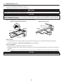
• The wires may be in reverse postion.
• Ensure that the color coded wires have been connected to
their appropriate places.
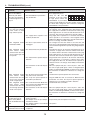
• Jump the OL and OC NO C NC I OC OL Y R G B
terminals. If the unit switch
to high speed, remove the
Dehumidistat or push button VE0098
and test it right beside the unit using another shorter wire.
If it works here, change the wire. If it doesn’t, change the
Dehumidistat or the push button.
• The Dehumidistat or push button
may be defective.
A. The supply motor does • The supply motor may be defective.
not work, but exhaust
motor works on both
high and low speeds.
• The supply motor capacitor or the
PCB may be defective.
B. The integrated control • The door is open and the unit is not
LED flashes RED.
unplugged.
C. The integrated control • The exhaust motor may be defective.
LED
flashes
RED;
exhaust motor does not
work on both high and
low speeds.
• The exhaust motor capacitor may be
defective.
8
• The transformer or the PCB may be
defective.
D. The integrated control
LED
flashes
RED;
exhaust motor does not
work on low speed but
works on high speed.
E. The integrated control
LED
flashes
RED;
exhaust motor does not
work on high speed but
works on low speed.
• Plug supply motor to J5 connector and exhaust motor to
J4 connector. If the integrated control LED flashes RED,
the supply motor is defective. If exhaust motor works, plug
back supply motor to J4 connector and exhaust motor to J5
connector, then check for supply motor capacitor validity.
• Plug supply motor capacitor to J7 connector and exhaust
motor capacitor to J6 connector. If the integrated control
LED flashes RED, the supply motor capacitor is defective. If
there is no change, the PCB is defective.
• Put a magnet over the door switch or close the door and
press once on the integrated control push button to reset the
unit. Check both high and low speeds using integrated push
button.
• Plug exhaust motor to J4 connector and supply motor to J5
connector. If supply motor works but exhaust motor does
not, exhaust motor is defective. If exhaust motor works, plug
back supply motor to J4 connector and exhaust motor to J5
connector, then check for exhaust motor capacitor validity.
• Plug exhaust motor capacitor to J6 connector and exhaust
motor capacitor to J7 connector. If exhaust motor works
but supply motor does not, the exhaust motor capacitor is
defective. If there is no change, check validity of transformer
or PCB.
• Move JU1 jumper from pins 2 and 3 to pins 1 and 2. Set
the unit on high speed (press 2 times on integrated push
button, the LED will light GREEN). If exhaust motor works,
the transformer is defective. If it still does not, change the
PCB.
• Check both low speed capacitor wires connections.
• The 18 µF low speed capacitor wires
may have a loose connection.
• The 18 µF low speed capacitor or • Plug the RED wire from J9 connector to RED wire from
the PCB may be defective.
transformer. If it works, the 18 µF low speed capacitor is
defective. If it is not working, the PCB is defective.
• The connection between BLUE wire • Check BLUE wires connection.
from J9 connector to BLUE wire from
transformer may be loose.
• The transformer or the PCB may be • Move JU1 jumper from pins 2 and 3 to pins 1 and 2. Set
defective.
the unit on high speed (press 2 times on integrated push
button, the LED will light GREEN). If exhaust motor works,
the transformer is defective. If it still does not, change the
PCB.
9
The defrost cycle does
• Ice deposits may be hindering the • Remove the ice.
not work (the fresh air
damper operation.
duct is frozen) OR the
• The damper rod or the port damper • Inspect these parts and replace if necessary.
fresh air distributed is very
itself may be broken.
cold.
• The damper actuator or circuit board • See point 5.
may be defective.
10
The integrated control • The 30-second boot sequence is not • See Section 3.1.1 Boot Sequence.
push button does not work.
completed.
18