1
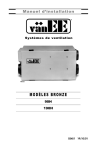
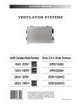
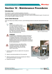
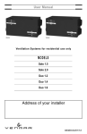
Installation Manual Ventilation Systems VB0014 MODELS Constructo 1.5 Constructo 2.0 03335 13/06/01 TABLE OF CONTENTS 1.0 TECHNICAL DATA . . . . . . . . . . . . . . . . . . . . . . . . . . . . . . . . . .3 1.1 1.2 1.3 Air Distribution (Normal Operation) . . . . . . . . . . . . . . . . . . . . . . . . . .3 Air Distribution (Defrost) . . . . . . . . . . . . . . . . . . . . . . . . . . . . . . . . . .3 Dimensions . . . . . . . . . . . . . . . . . . . . . . . . . . . . . . . . . . . . . . . . . . . . .3 2.0 TYPICAL INSTALLATIONS . . . . . . . . . . . . . . . . . . . . . . . . . . . . .4 2.1 2.2 2.3 Fully Ducted System . . . . . . . . . . . . . . . . . . . . . . . . . . . . . . . . . . . . .4 Exhaust Ducted System (Source Point Ventilation) . . . . . . . . . . . . .4 Simplified (Volume Ventilation) . . . . . . . . . . . . . . . . . . . . . . . . . . . . .4 3.0 INSTALLATION . . . . . . . . . . . . . . . . . . . . . . . . . . . . . . . . . . . .5 3.1 3.2 3.3 3.4 3.5 3.6 3.7 Locating and Mounting the Unit . . . . . . . . . . . . . . . . . . . . . . . . . . . .5 Planning of the Ductwork . . . . . . . . . . . . . . . . . . . . . . . . . . . . . . . . .5 Calculating Duct Size . . . . . . . . . . . . . . . . . . . . . . . . . . . . . . . . . . . . .6 Installing Ductwork and Registers . . . . . . . . . . . . . . . . . . . . . . . . . .7 Connecting Duct to the Unit . . . . . . . . . . . . . . . . . . . . . . . . . . . . . . .9 Installing Exterior Hoods . . . . . . . . . . . . . . . . . . . . . . . . . . . . . . . . . .9 Connecting the drain . . . . . . . . . . . . . . . . . . . . . . . . . . . . . . . . . . . .10 4.0 INSTALLATION OF THE CONTROLS . . . . . . . . . . . . . . . . . . . . . .11 4.1 4.2 4.3 Electrical Connection to Constructo Control . . . . . . . . . . . . . . . . .11 Electrical Connection to Optional Controls . . . . . . . . . . . . . . . . . . .11 Electrical Connection to the furnace . . . . . . . . . . . . . . . . . . . . . . . .11 5.0 AIR FLOW BALANCING . . . . . . . . . . . . . . . . . . . . . . . . . . . . .12 6.0 OVERALL VERIFICATION . . . . . . . . . . . . . . . . . . . . . . . . . . . .13 6.1 6.2 3-Position Switch . . . . . . . . . . . . . . . . . . . . . . . . . . . . . . . . . . . . . . .13 Optional Controls . . . . . . . . . . . . . . . . . . . . . . . . . . . . . . . . . . . . . . .13 7.0 MAINTENANCE . . . . . . . . . . . . . . . . . . . . . . . . . . . . . . . . . . .14 8.0 REFERENCES . . . . . . . . . . . . . . . . . . . . . . . . . . . . . . . . . . . .14 9.0 TROUBLESHOOTING . . . . . . . . . . . . . . . . . . . . . . . . . . . . . . .15 2 1.0 TECHNICAL DATA 1.1 Air Distribution (Normal Operation) STALE AIR TO OUTSIDE FRESH AIR TO BUILDING STALE AIR FROM BUILDING FRESH AIR FROM OUTSIDE VF0022 1.2 Air Distribution (Defrost) FILTERED AIR TO BUILDING STALE AIR FROM BUILDING VF0023 Outside Temperature Celsius (°C) -5 -15 -30 Fahrenheit (°F) 23 5 -22 Defrost Cycles Extended Defrost Cycles* Defrosting (min.) Operation time (min.) Defrosting (min.) Operation time (min.) between each defrost cycle 6 6 6 32 32 20 between each defrost cycle 10 10 10 30 20 15 * In a cold region, setup EXTENDED DEFROST by removing jumper JU1F on the circuit board. 1.3 Dimensions 6" (152 mm) 30 1/4" (768 mm) 17 1/8" (435 mm) 16 1/2" (419 mm) VK0029 3 2.0 TYPICAL INSTALLATIONS There are three (3) common installation methods. 2.1 Fully Ducted System (Primarily for homes with radiant hot water or electric baseboard heating. See figure 1.) Moist, stale air is exhausted from the high humidity areas in the home, such as bathrooms, kitchens and laundry rooms. Fresh air is supplied to bedrooms and principal living areas. The use of bathroom fans and range hood is suggested to exhaust stale air. Homes with more than one level require at least one exhaust register at the highest level. VH0002 2.2 Exhaust Ducted System figure 1 See 3.4.1 for details (Source Point Ventilation) (For homes with forced air heating. See figure 2.) Moist, stale air is exhausted from the high humidity areas in the home, such as bathrooms, kitchen and laundry room. Fresh air is supplied to the cold air return or the supply duct of the furnace.The use of bathroom fans and a range hood is suggested to exhaust stale air. See 3.4.2 Homes with more than one level require at least for details figure 2 one exhaust register at the highest level. NOTE: For this type of installation, it is not essential that the furnace blower runs when the unit is in operation, but we recommend it. VH0006 2.3 Simplified (Volume Ventilation) (For homes with forced air heating. See figure 3 or 4.) Fresh air and exhaust air flow through the furnace ducts which simplifies the installation.The use of bathroom fans and a range hood is suggested to exhaust stale air. NOTE: For this installation type shown in figure 4, furnace blower must be running when the unit is in operation. OR VH0032 figure 3 See 3.4.3 for details VH0007 4 figure 4 See 3.4.3 for details 3.0 INSTALLATION INSPECT THE CONTENTS OF THE BOX • Inspect the exterior of the unit for shipping damage. Ensure that there is no damage to the door, door latches, door hinges, dampers, duct collars, cabinet, etc. • Inspect the interior of the unit for damage. Ensure that the fan motor assembly, heat recovery core, insulation, dampers, damper actuator, and drain pan are all intact. • If the unit was damaged during shipping, contact your local distributor. (Claim must be made within 24 hours after delivery). • Use checklist included with the unit to ensure that no parts are missing. 3.1 Locating and Mounting the Unit Choose an appropriate location for the unit: • Within a heated area of the house (10°C / 50°F or more), usually the basement (in a furnace room, a laundry room, etc). • Away from living areas (dining room, living room, bedroom), if possible. • So as to provide easy access to the interior cabinet and to the control panel on the side of the unit. • Close to an exterior wall, so as to limit the length of the insulated flexible duct to and from the unit. • Close to a drain. (If no drain is close by, use a pail to collect run-off.) • Away from hot chimneys, electrical panel and other fire hazards. • Allow for a power source (standard outlet). VD0037 figure 5 VD0038 figure 6 CAUTION Make sure the unit is level. Hang the unit with the 4 chains and springs provided (see figures 5 and 6). 3.2 Planning of the Ductwork a) Follow the instructions in section 3.3 below to determine the appropriate duct diameters for your system. b) Keep it simple. Plan for a minimum of bends and joints. Keep the length of insulated duct to a minimum. c) Do not use wall cavities as ducts. Do not use branch lines smaller than 4”(102 mm) Ø. d) Do not ventilate crawl spaces or cold rooms. Do not attempt to recover the exhaust air from a dryer or range hood. This would cause clogging of the recovery core. Use sheet metal for the kitchen exhaust duct. e) Be sure to plan for at least one exhaust register on the highest lived-in level of the house if it has 2 floors or more. 5 3.0 INSTALLATION (CONT’D) 3.3 Calculating Duct Size Use the table below to ensure that the ducts you intend to install will be carrying air flows at or under the recommended values. Avoid installing ducts that will have to carry air flows near the maximum values and never install a duct if its air flow exceeds the maximum value. Duct Diameter Recommended Air flow end branches 5”Ø 70 cfm Maximum Air flow 40 cfm (19 l/s or 68 m3/h) 60 cfm (28 l/s or 102 m3/h) 75 cfm (35 l/s or 127 m3/h) 110 cfm (52 l/s or 187 m3/h) 120 cfm (57 l/s or 204 m3/h) 180 cfm (85 l/s or 306 m3/h) 185 cfm (87 l/s or 314 m3/h 270 cfm (127 l/s or 459 m3/h) 260 cfm (123 l/s or 442 m3/h) 380 cfm (179 l/s or 645 m3/h) 4”Ø (102 mm) 5”Ø (127 mm) 6”Ø (152 mm) 7”Ø (178 mm) 8”Ø (203 mm) main branch 6”Ø 140 cfm figure 7 140 cfm VI0003 NOTE: Examples 3.3.1 and 3.3.2 use imperial measures. The same calculation applies to metric measures. 3.3.1 Example of calculation Problem: My installation requires two exhaust registers (one for the kitchen, one for the bathroom). I will connect these registers to a main duct which will connect to the unit (high speed performance value of 140 cfm). What size of duct should I use for the main exhaust duct and for the two end branches leading to the registers? (See figure 7). Solution: Simplified method. (For a more detailed method of calculating duct size refer to the ASHRAE or HRAI HANDBOOK). Main duct: Table indicates for a 6”Ø duct: recommended air flow: 120 cfm; maximum air flow: 180 cfm. The high speed air flow of 140 cfm is close enough to the recommended value (120) and far enough away from the maximum value (180). Therefore a 6”Ø duct or larger is an appropriate choice for the main exhaust duct. End branches: Each end branch will have to transport an air flow of 70 cfm (140 divided by 2). Table indicates for a 5”Ø duct: recommended air flow: 75 cfm; maximum air flow: 110 cfm. The high speed air flow of 70 cfm is close enough to the recommended value (75) and far enough away from the maximum value (110). Therefore a 5”Ø duct or larger is an appropriate choice for the 2 end branches. N.B.: A 4”Ø duct would have been too small because the maximum acceptable value for a 4”Ø duct is 60 cfm. 3.3.2 Example of a design for a fully ducted system for a unit having a high speed performance of 222 cfm 4” 4” 5” 4”Ø 42 cfm 5”Ø 64 cfm 4”Ø 42 cfm 5”Ø 65 cfm 6”Ø 129 cfm 6”Ø 84 cfm 6” 7” 6” 6” 7” 6”Ø 93 cfm VI0004 6”Ø 96 cfm 4” 4” 6” 6”Ø 138 cfm figure 8 7”Ø 222 cfm 7”Ø 222 cfm 6 3.0 INSTALLATION (CONT’D) 3.4 Installing Ductwork and Registers ! WARNING 0 Never install a stale air exhaust register in a room where a combustion device is, such as a gas furnace, a gas water heater or a fireplace. 3.4.1 Fully ducted system (as illustrated in Section 2.1) Stale air exhaust ductwork: • Install registers in areas where contaminants are produced: kitchen, bathrooms, laundry rooms, etc. • Install registers 6 to 12 inches (152 to 305 mm) from the ceiling on an interior wall OR install them in the ceiling. • Install the kitchen register at least 4 feet (1.2 m) from the range top. • If possible, measure the velocity of the air flowing through the registers. If the velocity is higher than 400 ft/min (122 m/min), then the register type is too small. Replace it with a larger one. Fresh air distribution ductwork: • Install registers in bedrooms, dining room, living room and basement. • Install registers either in the ceiling or high on the walls with air flow directed towards the ceiling. (The cooler air will then cross the upper part of the room, and mix with room air before descending to occupant level.) • If a register must be floor installed, direct the air flow up the wall. 3.4.2 Exhaust ducted system (Source Point Ventilation) (as illustrated in Section 2.2) Stale air exhaust ductwork (same as for Fully Ducted System, described on point 3.4.1) Fresh air distribution: There are two methods for connecting the unit to the furnace: Method 1: supply side connection • Cut an opening into the furnace supply duct at least 18 inches (0.5 m) from the furnace. • Connect this opening to the fresh air distribution port of the unit as shown (use steel duct, see figure 9). • Make sure that the unit duct forms an elbow inside the furnace ductwork. • If desired, interlock (synchronize) the furnace blower operation with the unit operation (see section 4.3). Steel duct minimum 18’’ (0.5 m) VD0040 figure 9 7 3.0 INSTALLATION (CONT’D) Method 2: return side connection • Cut an opening into the furnace return duct at least 6 feet (1.8 m) from the furnace or at a minimum distance of 10 linear feet where the furnace return duct connects to the furnace cabinet. VD0041 figure 10 minimum 6’ (1.8 m) or 10’ (3.1 m) • Connect this opening to the fresh upstream air distribution port of the unit (see figure 10). NOTE: For Method 2, it si not essential that the furnace blower runs when the unit is in operation, but we recommend it. If desired, synchronize the furnace blower operation (see Section 4.3). 3.4.3 Simplified installation (Volume Ventilation) (as illustrated in Section 2.3) There are two methods (figures 11 and 12) for connecting the unit to the furnace: Method 1: return-supply Method 2: return-return Steel duct VD0042 figure 11 minimum 18’’ (0.5 m) minimum 6’ (1.8 m) VD0043 figure 12 minimum 3’ (0.9 m) minimum 6’ (1.8 m) or 10’ (3.1 m) upstream Stale air intake: • Cut an opening into the furnace return duct (at least 6 feet (1.8 m) from the furnace). • Connect this opening to the stale air intake port on the unit as shown. Fresh air distribution: (same instructions as for Method 1 or Method 2, Section 3.4.2). For method 2 (return-return), make sure there is a distance of at least 3 feet (0.9 m) between the 2 connections to the furnace. CAUTION If using Method 2, make sure the furnace blower operation is synchronized with the unit operation! See Section 4.3. NOTE: For Method 1, it is not essential to synchronize the furnace blower operation with the unit operation, but we recommend it. 8 3.0 INSTALLATION (CONT’D) 3.5 Connecting Duct to the Unit Insulated flexible duct: Use the following procedure for connecting the insulated flexible duct to the ports on the unit (exhaust to outside and fresh air from outside). a) Pull back the insulation to expose the flexible duct. b) Connect the interior flexible duct to the opening using a duct tie. c) Carefully seal the connection with duct tape. d) Pull the insulation over the joint and tuck it between the inner and outer rings of double collar. e) Pull the vapor barrier over the insulation and over the outer ring of the double collar. f) Apply duct tape to the joint making an airtight seal. Avoid compressing the insulation when you pull the tape tightly around the joint. A compressed insulation loses its R value and causes water dripping due to condensation on the exterior surface of the duct. CAUTION Make sure that the vapor barrier on the insulated ducts does not tear during installation to avoid condensation within the duct. a) VJ0001 b) VJ0002 c) d), e) VJ0003 VJ0004 f) VJ0005 Rigid duct: Use duct tape to connect the rigid ducts to the ports. CAUTION Do not use screws to connect rigid ducts to the ports. Make sure that the 2 balancing dampers are left in a fully open position before connecting the ducts to these ports (fresh air distribution port and stale air exhaust port as shown on figure 13 beside). VJ0011 figure 13 3.6 Installing Exterior Hoods Choose an appropriate location for installing the exterior hoods: • a minimum distance of 6 feet (1.8 m) between hoods to avoid cross-contamination • a minimum distance of 18 inches (457 mm) from the ground 9 3.0 INSTALLATION (CONT’D) Make sure the intake hood is at least 6 feet (1.8 m) away from any of the following: • dryer exhaust, high efficiency furnace vent, central vacuum vent • gas meter exhaust, gas barbecue-grill • any exhaust from a combustion source • garbage bin and any other source of contamination Refer to figure 14 for connecting the insulated duct to the hoods. Place the “FRESH AIR INTAKE” sticker, provided in the installation kit, on corresponding hood. An “Anti-Gust Intake Hood” should be installed in regions where a lot of snow is expected to fall. 6”Ø (152mm) Exhaust hood Intake hood 18” (457 mm) 18” 6’ (457 mm) (1.8 m) 6’ (1.8 m) Optional duct location 18” (457 mm) Tape and duct tie Caulking figure 14 VD0028 3.7 Connecting the Drain Inside view 12"(305 mm) 1 VO0010 To install the drain fittings, punch the 2 knock-out sections located at the bottom of the unit. 2 VO0003 In order to keep the drain pan intact, hand tighten the 2 plastic drain fittings to the unit using the gaskets, washers and nuts as shown. Join the 2 short sections to the tie wrap “T” junction and main tube as shown. VO0005 4 to drain VO0011 10 5 VO0004 3 Cut 2 sections of the plastic tube, about 12” (305 mm) long and attach them to each drain fitting. Make a water trap loop in the tube to prevent the unit from drawing unpleasant odors from the drain source. Make sure this loop is situated BELOW the “T” as shown. This will prevent water from being drawn back up into the unit in case of negative pressure. Run the tube to the floor drain or to an alternative drain pipe or pail. Be sure there is a slight slope for the run-off. 4.0 INSTALLATION OF THE CONTROLS 4.1 Electrical Connection to CONSTRUCTO Control OFF MIN MAX NOTE: Disregard other terminals (they are not used). F F I OC OL Y VE0042 R G B 4.2 Electrical Connection to Optional Controls MAIN PC BOARD 9 8 7 OL 5 OC 4 I 3 J3 J1 1 4 7 2 5 8 3 6 9 0L CRANK TIMER (Optional) PUSH-BUTTON SWITCHES (5 SWITCHES MAXIMUM) 0C I REAR VIEW PUSH-BUTTON SWITCHES VE0043A 4.3 Electrical Connection to the Furnace (optional) ! WARNING Never connect a 120-volt AC circuit to the terminals of the furnace interlock (standard wiring). Only use the low voltage class 2 circuit of the furnace blower control. W 4 WIRES R G Y THERMOSTAT TERMINAL Unit Control Module 9-PIN AMP PLUG J1 2 WIRES heating only wiring nuts W 4 7 2 5 8 3 6 9 GRAY R E D B R O W N GREEN RR N C G BLUE C YY F U R N A C E 24-VOLT TERMINAL BLOCK 1 N O C O M *FURNACE INTERLOCK RELAY 2 WIRES COOLING SYSTEM *FURNACE INTERLOCK RELAY, PART # 12658 VE0009A 11 5.0 AIR FLOW BALANCING WHAT YOU NEED TO BALANCE THE UNIT • A magnehelic gauge capable of measuring 0 to 0.5 inches in water (0 to 125 Pa) and 2 plastic tubes. • The balancing chart of the unit. PRELIMINARY STAGES TO BALANCING THE UNIT VP0009 • Seal all the unit ductwork with tape. Close all windows and doors. • Turn off all exhaust devices such as range hoods, dryers and bathroom fans. • Make sure the balancing dampers are fully open. • Make sure all filters are clean (if it is not the first time you balance the unit). VD0051 BALANCING PROCEDURE 1. Set the unit to high speed: Make sure that the furnace blower is ON if the installation is in any way connected to the ductwork of the cold air return. If not leave furnace blower OFF. If the outside temperature is below 0°C / 32°F, make sure the unit is not running in defrost while balancing. (By waiting 10 minutes after plugging the unit in, you are assured that the unit is not in a defrost cycle.) 2. Place the magnehelic gauge on a level surface and adjust it to zero. 3. Connect tubing from gauge to EXHAUST air flow pressure taps (see diagram). Be sure to connect the tubes to their fresh air flow appropriate high low fitting. If the gauge drops below zero, reverse the tubing connections. NOTE: It is suggested to start with the exhaust air flow reading because the exhaust has typically more restriction than the fresh air, especially in cases of fully ducted exhaust air flow and exhaust ducted installations. Place the magnahelic gauge upright and level. Record equivalent AIR FLOW of the reading according to the balancing chart. VP0010 4. Move tubing to FRESH air flow pressure taps (see diagram). Adjust the fresh air balancing damper until the FRESH air flow is approximately the same as the EXHAUST air flow. If Fresh air flow is less than EXHAUST air flow, then go back and adjust the exhaust balancing damper to equal the FRESH air flow. 5. Secure both dampers in place with tape or with a fastening screw. 6. Write the required air flow information on a label and stick it near the unit for future reference (date, maximum speed air flows, your name, phone number and business address). NOTE • Use conversion chart provided with the unit to convert magnehelic gauge readings to equivalent cfm values. • The unit is considered balanced even if there is a difference of +/- 10 cfm or +/- 5 l/s or +/-17 m3/h (+/- 0.015 inch in water) between the 2 air flows. VD0052 12 6.0 OVERALL VERIFICATION 6.1 3-Position Switch This procedure allows the installer to verify that all modes of operation are fully functional. During the verification of the 3-position switch, make sure that all optional remote controls are inactive. Set switch to Results expected fan speed / damper LOW HIGH low speed / open high speed / open REMOTE motor off / closed 6.2 Optional Controls First, set 3-position switch (located on the side of unit) to “REMOTE” position before checking the remote optional controls. CONSTRUCTO (6 different control scenarios to be tested) Results expected Fan speed / damper motor off / closed motor off / closed low speed / open high speed / open high speed / open high speed / open CO VC0014 Activate the push button. Note: To stop activation, push one time. ON VC0030 60-minute crank timer TURN PAST 20 OFF 10 Activate the timer. 20 30 Results expected: 1. Motor speed: high for up to 60 minutes. 60 13 40 50 VC0017 -5°C 23°F -20°C -4°F 20-minute push-button timer Results expected: 1. Motor speed: high for 20 minutes. 2. Indicator light on timer goes “ON”. M F O R T Z O NE 5°C 41°F #XXXXX Set dehumidistat dial to maximum counterclockwise maximum clockwise maximum counterclockwise maximum clockwise maximum counter-clockwise maximum clockwise 01/ 98 1 2 3 4 5 6 Set the slider switch to Off Off Min Min Max Max OFF MIN MAX 7.0 MAINTENANCE ! WARNING 0 Risk of electrical shocks. Before performing any maintenance or servicing, always disconnect the unit from its power source. • Review with the user the steps required for regular maintenance of his/her ventilation system. These steps are described in detail in the user manual: FOUR TIMES A YEAR: • • • • Inspect the intake hood, and clean if needed. Clean the filters. Clean the interior of the cabinet, and clean the door. Clean the condensation tray, and inspect the drain tubing. ONCE A YEAR: • Clean the heat recovery core. • Clean the blades of the blower wheels if needed. • Warn the user of the necessity to rebalance the system following a major house renovation or following the installation of any extra registers. • Make sure the user understands how to use the controls as described in the user manual. CAUTION Do not oil the motor. It is permanently lubricated. 8.0 REFERENCES • HVI, “Installation Manual for Heat Recovery Ventilators”, 1987 edition. • ASRHAE 1984 Systems Handbook, chapter 11, “Air Distribution Design for Small Heating and Cooling Systems”. R 2000 C LISTED Accepted in R-2000 Venmar Quality Assurance homes when installed according to R-2000 standards 14 C US LISTED Member of Home Ventilating Institute division of AMCA 9.0 TROUBLESHOOTING Note: Be sure to unplug and inspect the unit before proceeding with these steps. Start with point 1,then point 2 and so on. Start-up troubleshooting: Problems Possible causes 1. Unit doesn't work. • Erratic operation of the electronic circuit. • Unplug the unit. Wait for 30 seconds. Plug it back in. • The breaker in the electrical • Reset breaker. If it trips again, unplug the unit and call panel may be tripped. an electrician. • The door switch may be defective. • Using a multimeter, check for power across the switch (the door switch must be pushed in for this test). If there is no power, replace the switch. • The circuit board may be defective. • Jump BLACK and GREEN terminals and check if the motor runs on high speed (or jump BLACK and RED terminals and check if the motor runs on low speed) and the damper opens, the circuit board is not defective. (The door switch must be pushed in for this test). Replace the board if no voltage is detected. • The fan motor may be defective. • Unplug the unit and disconnect the fan motor (4 wires). Supply 120V directly to the GREY and ORANGE wires of the fan motor. Replace the motor if not working. • The 9-pin connector may have • Unplug the unit and check to make sure all the crimp connections a loose connection. are sound. Check the fan motor and the damper actuator connections as well. You should try this 2. The damper actuator doesn't work. • The 9-pin connector may have a loose connection. • The damper actuator may be defective. • The circuit board may be defective. 3. The wall control will not function. • The wire in the wall OR the wall control may be defective. • The wires may be in reverse position. • The wires may be broken. • There may be a short-circuit. 4. The 20-minute push-button switch doesn't work OR its indicator light doesn't stay on. • Switch may be defective. • Unplug the unit and check to make sure all the crimp connections are secured. Check the damper actuator connections as well. • Feed 120V directly to the damper actuator. If the problem persists, replace that damper actuator. • Replace the circuit board if the problem is not solved by the above. • Remove the wall control and test it right beside the unit using another shorter wire. If the wall control works there, change the wire. If it doesn’t, change the wall control. • Ensure that the color coded wires have been connected to their appropriate places. • Inspect every wire and replace any that are damaged. • With the help of a multimeter, check for continuity. • Jump the OL and OC terminals. If the unit switches to high speed then the wires are not the problem. Replace the push button. • Ensure that the color coded wires have been connected to their appropriate places. • The wires may be defective or may not be connected properly. 15 9.0 TROUBLESHOOTING Problems Possible causes You should try this 5. The defrost cycle • Ice deposits may be hindering • Remove the ice. doesn't work the damper operation. (the fresh air duct is • The damper rod or the port • Inspect these parts and replace if necessary. frozen OR damper itself might be broken. the fresh air distributed • The damper actuator might be defective. • Plug in the unit and select “OFF”. Press the door switch and is very cold.) see if the port damper closes. If it doesn’t close, feed 120 V directly to the damper actuator. If the port damper still doesn’t close, replace the damper actuator. • The circuit board might be defective. • Unplug the unit. Unplug the defrost sensor wire (see J4 on electrical diagram). Plug the unit back in. Select “MIN” and make sure the unit is adjusted for low speed operation (turn dial on Constructo control maximum counterclockwise). Wait 3 minutes. The unit should switch to high speed and the damper at the fresh air intake port should close (defrost mode). If this doesn’t happen, then replace the circuit board. 6. Unit on high speed • The thermistor may be defective. • If the defrost mode works well after having disconnected the every 20 min. per hour. thermistor wire (above test), then this means the thermistor is probably defective. You should replace it. Long term troubleshooting: Problems Possible causes 7. Cold air at registers. You should try this • The registers are poorly located. • Relocate the registers according to instructions in Section 3.4. • Unit continously on high speed. • Tell owner to set to low speed, especially during cold weather. • The temperature outside is extremely cold. • Suggest adding a ‘’duct heater” in the system. Consider connecting the “extended defrost” option (see electrical diagram). • The system needs rebalancing. • Rebalance the system (see Section 5). • The defrost is not working. • See point 5 above. 8. Persistent condensation • on windows. • • • • Refer to the user’s manual section 3.0. Dehumidistat defective. Occupants might need more controls. Hot tubs or pools present. Firewood in the house. • Unheated crawl space. 9. Noisy unit. • Fan wheel is out of adjustment. • Blower wheel dirty. • • • • • Refer to user’s manual section D. See point 4 on page 13. Suggest installing additional timers or dehumidistat. Cover these sources of humidity. Store wood in a closed room with a dehumidifier or have the room well vented with outside air or store the wood outside. • Prevent circulation of air from the crawl space to the house. If the crawl space has an earth floor, cover it with a vapor barrier and 2 to 3 inches (5 to 8 cm) of gravel. • Remove the fan assembly and tighten the loose parts. • Remove, clean and review with user the maintenance requirements in his manual. • Replace. • Replace. • Damaged fan assembly. • Unbalanced wheel. 10. Noisy registers at “max” • The air ducts are too short. speed. • The register is too small. • Install a silencer. • Replace with larger register. 11. Very little or no air flow. • Dirty filters, exterior hoods clogged up. • Clean filters and/or hoods and review with user the maintenance instructions in his manual. • Rebalance (see Section 5). • The system may need rebalancing. 12. Snow in the unit. • The exterior intake hood is poorly located. • Clear snow away from hoods and warn user he/she should regularly remove snow from near the exterior hoods. • Install the “Anti-Gust Intake Hood”, part number 12570. • Turn off the unit during snow storms. 13. Condensation, frost or ice inside the insulated ducts. • The duct insulation is defective and /or the vapor barrier is torn. • Make sure there are no tie ducts or duct tape compressing the insulation. Check the insulated ducts for any damaged or weak spots. 16