1
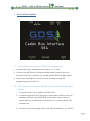
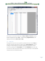
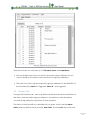
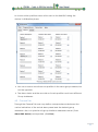
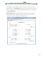
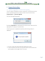
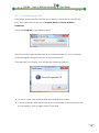
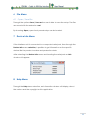
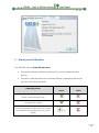
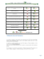
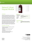
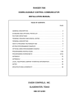
CBI-064 Caddx to KNX-BUS Interface User Manual GDS Intelligence in Buildings El. Venizelou 116 Nea Erithrea 14671 Tel: +30 2108071288 Email: [email protected] Web: gds.com.gr Contents 1 Device Description....................................................................................................... 2 1.1 Unit interface connection CBI-064 for programming ................................ 2 1.2 Unit interface connection CBI-064 for operation with the alarm system .................................................................................................................................. 2 2 Basic Device features ................................................................................................. 3 3 Communication elements ......................................................................................... 3 4 Programming with the Serial Alarm application ................................................. 4 4.1 Zones Tab................................................................................................................ 5 4.2 Partitions Tab.......................................................................................................... 6 4.3 General Tab ........................................................................................................... 7 5 Program Device Menu ............................................................................................... 9 5.1 Software upgrade per unit (Firmware Upgrade) ........................................ 9 5.2 Commissioning the Unit .................................................................................... 10 6 File Menu....................................................................................................................... 11 6.1 Open / Save File ................................................................................................. 11 7 Device Info Menu ....................................................................................................... 11 8 Help Menu .................................................................................................................... 11 9 Alarm panel indicators ............................................................................................. 12 10 Remote device restart .......................................................................................... 13 11 Remote device restart .......................................................................................... 14 12 Filtering data in the exported Commands of KNX-BUS ............................... 14 13 Remote access to the keypad .......................................................................... 15 14 Unit electrical characteristics.............................................................................. 15 1 1 Device Description 1.1 Unit interface connection CBI-064 for programming 1. Connect the unit’s interface power supply (6-12 VDC). 2. Connect the RS-232 port (Program mode/Alarm Mode) of the unit interface with the Computer via a male-female RS-232 straight cable. The power of KNX BUS connection is not necessary during the programming of the device. 1.2 Unit interface connection CBI-064 for operation with the alarm system 1. Connect the device to KNX BUS (20-33 VDC). 2. Connect the port RS-232 (program mode/alarm mode) of the unit interface with the subunit NX-587E of the alarm system (which is connected to the data BUS of the alarm) via a male-male RS -232 crossed wire. 3. Connect the power supply of the unit CBI-064 Interface (6-12 VDC). 2 2 Basic Device features Sending the state of each zone (Transmits on change) Selectively sending each zone’s status at start-up Provides the partition status (armed/disarmed) – (troubled/not troubled) Sending of states can be enabled/disabled in runtime New firmware can be loaded when available Communication error with alarm system is indicated with individual object Safety feature overwrites attempt to affect real zone status if another device writes to same group address Alarm keypad display messages can be transferred over the BUS Alarm keypad status LEDs and sound notifications can be transferred over the BUS LED indicators to show operating state of the device Remote restart of the device Alarm Keypad and display emulation 3 Communication elements i. ii. iii. Zones: 1 bit elements. Each element is assigned to a group address. The device transmits value 1 if the respective zone changes from normal (closed state) to disturbed (open) and vice versa. Transmission of each zone’s status upon power up can be controlled individually for each zone Partition alarm status (All 8 partitions are supported): 1 bit elements. Each element is assigned to a group address. The device transmits 1 if the respective partition generates an alarm and 0 when returning from alarm to not alarmed state. Transmission of each partition’s status upon power up can be controlled individually for each partition Partition arm status (All 8 partitions are supported): 1 bit elements. Each element is assigned to a group address. The device transmits 1 if the respective partition is changing from not armed to armed state and 0 when changing from armed to not armed state. Transmission of each 3 iv. v. vi. vii. viii. ix. x. xi. xii. xiii. xiv. xv. xvi. partition’s status upon power up can be controlled individually for each partition. Alarm KNX device: 14 bytes element. Used to send commands to the central alarm unit via KNX. (See detailed description below) Keyboard buzzer: 1 bit element following the keypad’s buzzer state. Value 1 to the respective group address means buzzer is sounding and value 0 means not sounding, Error: 1 bit element. Device is writing value 1 to the assigned group address to indicate that communication between the device and the alarm unit is broken and 0 when communication is restored. Armed LED: 1 bit element following the Armed Led status. Value 1 means led is lit Value 0 means led is off. Fire LED: 1 bit element following the Fire Led status. Value 1 means led is lit Value 0 means led is off. Stay LED: 1 bit element following the StayLed status. Value 1 means led is lit Value 0 means led is off. Exit LED: 1 bit element following the Exit Led status. Value 1 means led is lit Value 0 means led is off. Cancel LED: 1 bit element following the Cancel Led status. Value 1 means led is lit Value 0 means led is off. Ready LED: 1 bit element following the Ready Led status. Value 1 means led is lit Value 0 means led is off. Power LED: 1 bit element following the Power Led status. Value 1 means led is lit Value 0 means led is off. Chime: 1 bit element following the Chime status. Value 1 means chime is activated Value 0 means chime is off. Bypass LED: 1 bit element following the Bypass Led status. Value 1 means led is lit Value 0 means led is off. Display elements: 14 bytes elements. Each element is assigned to a group address. Device writes to the respective group address the string showing to the respective keypad’s LCD display line. This Information can be used either for visualization or for further processing of various alarm system conditions. If combined with keypad emulation a virtual alarm keypad can be created in a visualization program. 4 Programming with the Serial Alarm application Through Serial alarm application, the device is assigned with the various group addresses corresponding to the Caddx alarm system functions. While the Serial Alarm application is running displays the following window: 4 The window is structured in three tabs ( Zones, Partitions, General) and the folder management menus (File) , programming (Program Device) and displayed information (Device Info , Help) 4.1 Zones Tab Through the Zones tab, user may define matches between zones ( Zone) of the alarm and the desired group address field ( Group Addresses). Also it is possible to add descriptive comments regarding the operation of each zone/Group address (field Description). The field Initialization allows the user to choose for which zone alarm the device will send the status to the KNX-BUS during the device’s initialization phase. 5 With this software we can plan up to 192 alarm zones and 8 partitions. We can assign more than one zone in the same group address, but we cannot assign to the same zone more than one group addresses. The state is sent through the respective group addresses to the KNX-BUS of the (Faulted/Ok) (Value 1= Triggered, Value 0 = Not triggered. 4.2 Partitions Tab Through the Partitions tab, user may define relations between the partitions of the alarm and the desired group address. It is possible to add descriptive comments regarding the operation of each partition. The status of each partition is described in two parts, which are the alarm status (alarm partition status) and the arm status. The field Init, allows the user 6 to choose which partition status will be sent to the KNX-BUS during the device’s initialization phase. We can connect more than one partition in the same group address, but not the opposite. The alarm status and the arm status of each partition must have different Group Addresses. 4.3 General Tab Through the General Tab user may define correspondences between the various indications of the actual alarm panel and the desired group addresses. Also, two special unit group interface addresses are set ( field Alarm KNX device) and reported ( field Error ). 7 On the Leds table the addresses for the various lights on the actual alarm keyboard are set. The Initialization fields allows the user to select which values will be sent automatically during the initialization phase of the unit (excluding the Alarm KNX device) . Update Wrong Values field enables/disables the automatic overwriting. If a group address receives a different value than the actual alarm system, it immediately transmits a telegram with the right value. 8 5 Program Device Menu 5.1 Software upgrade per unit (Firmware Upgrade) If the PC and the CBI-064 are correctly connected via RS-232 port and you have a valid firmware file for the device, then choose from the menu: Program Device -> Firmware Upgrade Then the following Dialog opens: By pressing Download the valid update file can be chosen. Then select the appropriate PC serial port communication. Once the process is completed successfully, the following window is displayed: On error, make sure that the serial port settings are correct. If the error persists then reboot the unit (disconnect and reconnect the power supply), and try again after 15 seconds. 9 5.2 Commissioning the Unit If the alarm panel and the CBI-064 are correctly connected via the RS-232 port, then choose from the menu Program Device->Group Address Download. Then press Program in the display panel: Then choose the appropriate serial port communication for your computer, and the programming process of the unit commences. If the process is successful, you will see the following window: On error, make sure that the serial port settings are correct. If the error persists then reboot the device (disconnect and reconnect the power supply), and try again after 15 seconds. 10 6 File Menu 6.1 Open / Save File Through the options Save / Save as the user is able to save the setup. The files are saved with the extension .xml. By choosing Open, a previously saved setup can be loaded. 7 Device Info Menu If the interface unit is connected to a computer's serial port, then through the Device Info menu selection, is possible to get information on the specific device like the product number and production date. After selecting the Device Info menu and inserting the serial port an Info window will appear: 8 Help Menu Through the Help Menu selection, an information window will display, about the version and the copyright on this application. 11 9 Alarm panel indicators The CBI-064 unit has three LED indicators. The green indicator indicates that the DC power is supplied to the device. The yellow and red indicators, indicate different operating statuses as shown in the following table: Operating status Yellow LED Red LED status status Basic operation/readiness status all the communications work Initializing phase (duration approximately 2 seconds after restart) Restart Phase 1 – checking for available software upgrade (duration about 4 seconds immediately after applying the DC power supply) Low 12 Restart Phase 2 – check for available software upgrade (duration about 2 seconds from restart. Low Low Group Addresses programming ( Group Address Download ) Download new software tool Phase ( Firmware Download) High Control of righteousness logged operating software Phase( Firmware Check) Low Communication Error with KNX-BUS(requires a reboot of the device during the correction) Low Communication error with the alarm system Communication Error with the alarm system and with the KNX-BUS Low Low Low Initialization Unit Error Explanation Of Symbols =On , =Off , High/Low = Flashing Fast/slow 10 Remote access to the device If a value is written to the device not following the CT$ format described above, the transmitted value is sent to the alarm central unit as if it was transmitted from the keypad. In order to use this function we must first assign a Group address to the required field (Alarm KNX device). We must also use the APR-PRT3 unit in order to communicate with the alarm panel. For example, to send the pin number «1234» through the ETS program we select 14 Bytes telegram, 16.000 data type, ASCII and "1234" as value. 13 11 Remote device restart For the remote Unit restart it is required to send a 5 characters telegram with the value “RESET “ to the Group Address indicated by the Alarm KNX device field described above. In ETS application select the telegram length to 14 Bytes, 16.000 data type, and word "RESET" as value. 12 Filtering data in the exported Commands of KNX-BUS The user via an appropriate telegram to KNX-BUS, can filter the transmitted events from the device. The structure of the telegram must be the following: “CT$ XY” where XY is a 2 digits decimal number calculated as follows: XY calculation Transmit the messages on the alarm keypad screen Transmit the alarm keypad LED status and sound notifications 8 4 Add the values corresponding to the desired filtering Transmit the changing to the status of the alarm zones Transmit the partitions state changing 2 1 Configuration Number = Sum of the corresponding values For example, if only the zones and partitions in KNX-BUS are required we will calculate the configuration number: 2+1=3 So the string "XY" is "03" and we must send a telegram with content “CT$03” to activate the desired filter. 14 If we need to activate the filter from an ETS command we should define telegram length 14 Bytes, 16.000 data types ASCII and to send “CT$ 03” as value for this example. The device factory default is 15 (all active) 13 Remote access to the keypad If a value is written to the device not following the CT$ format described above, the transmitted value is sent to the alarm central unit as if it was transmitted from the keypad For example, send the pin number «1234» through the ETS program we select 14 Bytes telegram, 16.000 data type, ASCII and "1234" as value. 14 Unit electrical characteristics Operating temperature: 5 ⁰C up to 45⁰C Storage Temperature: 0 ⁰C up to 55⁰C Maximum operating voltage: 12 V DC Max current : 100 mA 15