1
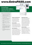
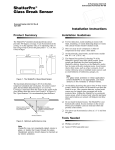
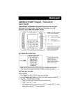
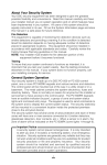
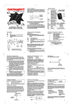
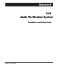
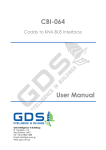
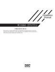
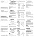
800-04965 8/09 Rev. A
ADEMCO CE3
Code Encryptor 3
INSTALLATION AND SETUP GUIDE
GENERAL INFORMATION
CODE
ENCRYPTOR 3
The Code Encryptor 3 (CE3) provides wireless control for
arming/disarming a security system, opening/closing a garage door, and
activating a relay output (ex. turning on a light). The CE3 consists of a
Receiver and wiring harness, remote control keyfob, and a status LED
with optional mounting plate.
The most important factor for range and reliability is the mounting
location of the Receiver. Select a location that is as centrally located as
possible. Keep in mind that the user will want to control the operation of
the garage door from the driveway, and will also expect the use of the
remote for alarm on/off in the area of entry and exit.
REMOTE
KEYFOB
Although you can wire the Receiver to the panel, it may reduce labor by
installing the CE3 Receiver at the point of entry and wire it to a nearby
keypad. In most cases this is the garage entry, which will provide an easy
installation for garage door open/close, status indicator, and alarm
controls through the keypad.
CODE ENCRYPTOR 3
RECEIVER
WIRE
HARNESS
LED AND
MOUNTING
PLATE
IMPORTANT: Do not mount the Receiver module inside the alarm panel
enclosure; it will reduce the reception of the remote keyfob.
LED STATUS INDICATOR
Red = Armed
Green = Disarmed
Yellow = Alarm
CE3-006-V0
Installation Steps
1. Connect the CE3 Receiver to the control panel.
2. Program the CE3:
a. Associate the Receiver with the connected control using Automatic Recognition.
b. Program a user code for the Remote Keyfob.
3. Wire optional features, if used (Status LED, Garage Door Opener, Relay Outputs).
4. Test the System.
CONNECTING THE RECEIVER TO THE CONTROL PANEL
The Receiver can be wired either to the control’s terminals
or to a keypad’s terminals.
CODE
1. Unplug the Receiver from the wire harness.
ENCRYPTOR 3
PROGRAM
BUTTON
NOTE: You can make these connections at the control or
at the keypad itself. If you place the Code Encryptor 3 in
the garage or any other location away from the control,
you may choose to wire the Code Encryptor 3 directly to
the keypad.
Summary of Basic Connections
Wire Color
Connection
Red
Keypad Red or Aux (+)
Black
Keypad Black or Aux (-)
Green
Keypad Green (control Data In)†
Yellow
Keypad Yellow (control Data Out)
† not used on GE Caddx NX panels
YELLOW
GREEN
RED
2. Connect the Red, Black, Yellow and Green wires to the
keypad or control’s terminals as shown in the diagram.
BLACK
RECEIVER
LED
ALARM PANEL
IN
AUX
OUT
DATA
ARMED
1
OFF
2
AWAY
3
STAY
READY
4
MAX
5
TEST
6
BYPASS
7
INSTANT
8
CODE
9
CHIME
READY
0
SYSTEM
KEYPAD
#
CE3-011-V0
PROGRAMMING THE CODE ENCRYPTOR 3
Programming involves first associating the module with the control with which it is being used (auto recognition), and then
programming the remote control’s user code.
Automatic Recognition
1. Make sure the alarm panel is powered up and operating. The wire harness
should still be disconnected from the Receiver.
2. While watching the LED light on the CE3 Receiver, plug the wire harness
connector into the Receiver.
3. The Receiver’s LED will blink one time on power up. After about 2 seconds,
count the flashes that you see. The corresponding flashes indicate which
panel the Code Encryptor 3 has detected. Refer to the table below.
CODE
ENCRYPTOR 3
PROGRAM
BUTTON
RECEIVER
LED
CE3-012-V0
Control Panel Detection Table
No. of Flashes Alarm Panel detected by the CE 3
No Alarm connected (CE3 defaults to relay mode) See “Default Mode”
1
2
Future use
3
**GE/NX4, NX6, NX8, NX8V2
4
Future use
5
Honeywell - Non-Addressable (Vista & 4110, XM, XMP)
6
Honeywell - VISTA Addressable (Vista P series controls 10, 15, 20, 21iP, 40, 50, 128, 250)
7
DSC- PowerSeries 816/832/5010/5020, PC1616/1832
8
DSC PC1550, 2525, 2550, 3000
9
**Napco P816/1632/3200
10
Future use
** For these panels, open top cover and slide switch away from LED
The Code Encryptor 3 on the following panels self-enroll themselves as a specific keypad address code.
Control
Address
Honeywell addressable
3 (VISTA-40, 50, 128, 250)
Honeywell addressable (P controls) 17
IMPORTANT: DO NOT USE ANY OF THESE ADDRESS CODES IF YOU ARE USING ONE OF THE ABOVE CONTROLS.
Example: If you are using a Honeywell Vista P series control, no keypads can use address 17 because the CE 3 will automatically
enroll itself as address 17.
NOTE: If you are using the Honeywell Touchscreens, please remove them when Programming the Code Encryptor 3.
Programming the User Code
A user code for the Code Encryptor 3 must be programmed in the security system and in the CE3 Receiver. This provides the
system with a user code for arming and disarming of the control.
To program a user code into the Receiver, do the following:
1. Verify that the four-digit code you plan to teach the Code Encryptor 3 is a valid four-digit user code. Example: From the
keypad use that four-digit code to arm the panel. If the panel arms, the code is good. If it does not, program that user code into
the alarm panel. – The Code Encryptor 3 uses that four-digit code to arm and disarm the panel, thus that code must be valid.
NOTE: We recommend using a user code that the user cannot change. If the user code that is programmed into the Receiver
module is changed, the Code Encryptor 3 will not disarm the control panel.
2. Press and HOLD the program button on the Receiver. The LED will light. Continue to hold program button until the LED
turns OFF (in about 7 seconds). When the LED turns off, release the program button. The LED will begin to flash rapidly.
3. Using the keypad, slowly and firmly enter the four-digit user code (no other commands). After the fourth entry the LED will
stop flashing. This code has now been entered into the Code Encryptor’s non-volatile memory. The Code Encryptor will
remember this user code in the event of a power failure. To change to a new user code, repeat steps 2 and 3 above.
Adding/Deleting Remotes
To Add a New Remote
To Delete All Remotes
To add a remote to your Code Encryptor 3, do the following:
1. PRESS AND RELEASE the program button on the receiver.
The LED on the receiver will come ON.
2. Immediately PRESS button 1 on the new remote control
THREE TIMES. The LED on the receiver should go OFF
indicating the remote has been learned.
If the LED on the receiver stays ON, the remote has not
been learned. Remove and replace the harness, wait 15
seconds while auto recognition occurs and follow these
instructions again.
–2–
To delete a lost or stolen remote from the Code Encryptor 3,
you must purge the entire memory. This will delete all of the
current remotes. You will then have to add them back into
memory.
To purge, PRESS AND HOLD the program button. The LED
will come ON for four seconds, then go OFF, and finally it will
come ON again, indicating that all the remotes in memory
have been purged. Release the program button and follow the
To Add a New Remote instructions.
WIRING FOR OPTIONAL FEATURES AND APPLICATIONS
Summary of Harness Wire Functions
Purpose
Keypad
Connections
LED Status
Relay Output
Button
Garage Door
Opener
Entry/Exit zone
Wire Color
Red
Black
Green
Yellow
Purple
White/Purple
Blue/Green
Brown/White
Brown
White
Red/White
Gray
Function
Keypad Red or Aux (+12VDC)
Keypad Black or Aux (–)
Keypad Green (control Data In); Not Used on GE Caddx NX panels
Keypad Yellow (control Data Out)
LED Status Light Purple wire (Red light)
LED Status Light white/purple (Green light)
Channel 4 N/C (5amp)
Channel 4 N/O (5amp)
Channel 4 Common (5amp)
Channel 3 Common (Garage Door Pushbutton)
Channel 3 N/O relay (Garage Door Pushbutton)
Channel 1 (-) momentary output
Wiring the Status LED
The status LED is a low voltage type and must be wired to
the Code Encryptor 3. If you attempt to connect it any other
way, the LED will burn out and will NOT operate again.
Status LED Indications
LED Action
Red LED Flashing
Red LED Solid
Green LED Flashing
Green LED Solid
Yellow LED Flashing Rapidly
PURPLE (LIGHTS LED RED)
Indication
Away mode
Stay mode
Not Ready
Ready
Alarm occurred
STATUS
LED
BLACK (COMMON)
WHITE / PURPLE (LIGHTS LED GREEN)
CODE
ENCRYPTOR 3
RECEIVER
CE3-004-V0
Wiring to a Garage Door Opener (Channel 3 Application)
When button 3 is pressed, it activates a momentary contact closure for opening and closing a garage door. Occasionally, you may want
to use Channel 3 for control of other optional accessories (i.e., garage door motor, Malibu lighting, sprinklers, X-10 automation).
All garage doors have a wall mounted push button that
activates the door via a two-wire connection. Make your
connection at the push button switch or at the garage door
motor where these two wires terminate. Connect the red/white
and white wires from the CE3 to these two wires as shown. If
you choose to connect to the motor, trace the wires from the
push button to the motor and determine the proper connection
point. Most garage doors (except MOM Crusader models) use
terminals #1 and #2. For MOM Crusader models, use
terminals #2 and #3.
TYPICAL GARAGE DOOR OPENER
TERMINALS
1
2
3
WHITE (CHANNEL #3 COMMON)
RED / WHITE (CHANNEL #3 OUTPUTS)
CODE
ENCRYPTOR 3
RECEIVER
CE3-005-V0
Channel 4 Applications
When Button 4 is pressed, it activates a 5A Form C relay (Common, N/O/, N/C). You can use this output trigger for a 2nd garage
door motor, Malibu lighting, sprinklers, or an X-10 power flash module to interface with lighting, perhaps to illuminate the
walkway as the users leave and return home.
Default Mode
When the Code Encryptor 3 is not connected to the data bus of a control panel, it acts as a 2-relay module.
Button 1 triggers Channel 3 - Relay 1 (momentary).
Button 2 triggers Channel 4 - Relay 2 (momentary).
Channel 1 Momentary (-) Output (Optional)
When you momentarily press button 1 on the Code Encryptor 3 remote, the Gray wire momentarily sends a 500ma (-) output.
You can use this output to trigger an exit/entry zone to ensure the panel goes into Away mode.
PANIC MODE
Press and hold buttons 1 and 2 on the remote control for police panic. This will cause the panel to go into a panic mode. Cancel
Panic at a keypad. THE REMOTE WILL NOT CANCEL A PANIC.
Activating panic mode
NOTE: This is the default setting of the Code Encryptor 3.
If you have previously programmed remote panic “OFF” and would like to turn it back “ON” follow the steps below. If this is a
new installation, Panic “ON” is the DEFAULT setting for the Code Encryptor 3.
1. Unplug the wire harness from the Code Encryptor 3.
2. Press and HOLD the program button.
3. While HOLDING the program button, plug the Code Encryptor 3 harness back in. The LED located on the front will turn ON.
4. Immediately release the program button. Auto recognition will start.
IF NECESSARY, PROGRAM THE ALARM PANEL FOR KEYPAD PANIC.
–3–
Deactivating Panic Mode
In the event the user does not want to access a panic button through the remote control, it can be deactivated from the Code
Encryptor 3’s memory.
1. Unplug the wire harness from the Code Encryptor 3.
2. Press and HOLD the program button.
3. While HOLDING the program button, plug the CE 3 harness back in. The LED located on the front will turn ON.
4. Wait until the LED turns “OFF”.
5. Once the LED has turned “OFF” release the button. Auto recognition will start.
PANIC
HOLD
BOTH
TEST THE REMOTES
Press and Release button 1 to Arm “Away”
Press and Release button 2 to “Disarm”
Press and Hold button 1 for 3 seconds to Arm “Stay” or “Bypass”
Press and Hold buttons 1 and 2 for two seconds to activate “Panic”
NOTE: The Code Encryptor 3 will arm in the AWAY mode even if you
are outside the house. We do however recommend that you Arm the
alarm system within sight of the status LED or keypad to verify that
the system has received and responded to your remote request.
ARMED
GARAGE
DOOR
OPEN/CLOSE
DISARMED
PROGRAMMED
RELAY
OUTPUT
CE3-002-V0
TROUBLESHOOTING
PROBLEM
I press Button 1 but nothing happens.
I press and hold buttons 1 and 2 and I do
not get a panic.
I am using a DSC 1832 or any Power
Series and the alarm will not ARM with
the remote.
I am using a DSC Power Series and the
alarm will not DISARM with the remote.
I am using a GE Caddx NX panel and it
will only ARM in the STAY mode.
Unit does not seem to identify the panel I
am using.
SOLUTION
Did you program a valid four-digit user code to the Code Encryptor 3?
NOTE: The code you program to the Code Encryptor 3 must be a master code or one of
the current user codes.
Press button 3. If you do NOT hear a “click” at the receiver, see To Add a New Remote in
the Adding/Deleting Remotes section and learn that remote into the Code Encryptor 3.
Did you program the panel for keypad panic?
Program the Code Encryptor 3 for panic. Turn ON Panic (see Panic Mode section)
Make sure you program the Alarm panel for “Quick Key Enable,” programming section
015, light #4 is ON. Power down the alarm panel and power it back up. Wait at least 60
seconds before you attempt to use the remote control.
Enter panel programming. Go to programming section 017. Make sure light #1 is on.
Power down the panel, wait at least 60 seconds and power the panel back up.
Reprogram the user code to the CE3 receiver.
Call Technical Support at 800-645-7492.
SPECIFICATIONS
Technical Support: M-F 8AM-5PM EST (800) 645-7492; Sales: (858) 513-1224
• 12VDC Power Input
• Channels 1 & 2 Data outputs
• Channel 3 Relay (N/O, Common) 10amp - momentary
• Channel 4 selectable: Form C Relay (N/O, N/C, Common) 5amp - momentary
• Channel 5 (top 2-buttons at same time) - Keypad panic data output (Programmable On or OFF)
Frequency: 433 MHz
Stand by Power Consumption: 13mA on standby (40mA max)
Temperature Range: -5°F to 160°F (Indoor use only)
Remote Control Battery: 6VDC Mini (2x Part #CR-2032) Replace battery once a year.
Receiver:
FEDERAL COMMUNICATIONS COMMISSION (FCC) PART 15 STATEMENTS
The user shall not make any changes or modifications to the equipment unless authorized by the Installation Instructions or User's Manual. Unauthorized changes or
modifications could void the user's authority to operate the equipment.
CLASS B DIGITAL DEVICE STATEMENT
NOTE: This equipment has been tested and found to comply with the limits for a Class B digital device, pursuant to part 15 of the FCC Rules. These limits are designed
to provide reasonable protection against harmful interference in a residential installation. This equipment generates, uses and can radiate radio frequency energy and, if
not installed and used in accordance with the instructions, may cause harmful interference to radio communications. However, there is no guarantee that interference
will not occur in a particular installation. If this equipment does cause harmful interference to radio or television reception, which can be determined by turning the
equipment off and on, the user is encouraged to try to correct the interference by one or more of the following measures:
• Reorient or relocate the receiving antenna.
• Increase the separation between the equipment and receiver.
• Connect the equipment into an outlet on a circuit different from that to which the receiver is connected.
• Consult the dealer or an experienced radio/TV technician for help.
INDUSTRY CANADA (IC) STATEMENTS
This device complies with RSS210 of Industry Canada. Operation is subject to the following two conditions: (1) This device may not cause harmful interference, and (2)
This device must accept any interference received, including interference that may cause undesired operation.
This Class B digital apparatus complies with Canadian ICES-003.
Cet appareil numérique de la classe B est conforme à la norme NMB-003 du Canada.
Ê800-04965iŠ
800-04965 8/09 Rev. A
2 Corporate Center Drive, Suite 100
P.O. Box 9040, Melville, NY 11747
Copyright © 2009 Honeywell International Inc.
www.honeywell.com/security