1
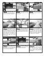
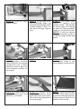
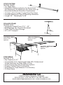
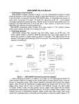
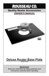
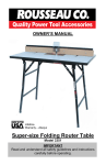
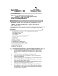
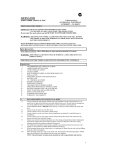
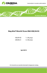
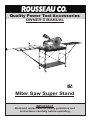
Quality Power Tool Accessories
OWNER’S MANUAL
Miter Saw
Super Stand
Models 2875/2875XL
IMPORTANT
Read and understand all safety guidelines and
instructions carefully before operating.
GENERAL INFORMATION
You have purchased a ROUSSEAU CO. 2875-2875XL MITER SAW SUPER STAND. This
unit is especially useful to the finish carpenter and cabinet or furniture builder. This stand
supports stock while you cut and provides stops out to 84”. It is easy to store, mobile with
locking casters and has instant set up. It fits most 10” - 15” saws up to 27-1/4” wide (36”
wide with 2875XL). Optional right hand stop system is available (3800R) .
WARRANTY
This product has a lifetime warranty to the original purchaser that applies to defects in
materials and workmanship only. We will repair or replace the product or part(s) at our
discretion. This warranty does not apply to product failure or defects due to direct or indirect
misuse, abuse, negligence, accidents, alterations, repairs or lack of maintenance. The
item must be shipped prepaid to our Clarkston, WA location. If items must be returned
for warranty service, call to receive a Return Goods Authorization (RGA) number and
further instruction.
SAFETY GUIDELINES
THIS SECTION CONTAINS IMPORTANT SAFETY INFORMATION CONCERNING A
HAZARD THAT MAY CAUSE SERIOUS INJURY OR DEATH, and/or damage to stand or
equipment if used improperly. Please read the following instructions very carefully.
Always set stand on level ground or floor surface, making sure all legs
are in contact with the ground or floor with casters locked. Failure to do
so could result in tipping or rolling of the table causing saw movement
and injury to the operator or to the equipment.
Be sure saw is bolted in securely. Failure to do so could result in injury
to self or saw.
Make sure top of saw base is level with arms. Failure to do so could
result in kickback, causing injury to self and/or saw.
When using adjustable stops, always hold work tight to table at a safe
distance from blade, until blade has come to a complete stop. Failure to
do so could result in kickback, causing injury to self, saw, or work piece.
When cutting small pieces use a hold down stick to hold work
in place until blade has stopped. Failure to do so could result in
kickback, causing injury to self, saw, or work piece.
Allow blade to stop at bottom of travel before raising. Failure to do
so could result in kickback, causing injury to self, saw, or work piece.
Keep fingers clear of hinge mechanisms when dropping support wings.
Failure to do so could result in pinching
or loss of fingers.
Step 19 Slide the remainder of the tape into the rear
tape groove.
Step 20 Line up the 60”
mark on the tape measure with the hairline
indicator.
Step 21Mark tape with a
pencil 1/4” in from the left
end.
Step 22 Slide the tape
out approximately 18” and
break it off at the pencil
mark.
Step 23 S l i d e i t b a c k
through the extrusion and
out the right side. Repeat
steps 15-18 (substituting
32” with 60”)
Step 24 Make final adjustments if needed by adjusting the hairline indicator
to either the left or right.
Loosen the two mounting
screws, set the hairline,
and retighten the screws
while holding the hairline
firmly in position.
An additional tape measure may be purchased to slide into the groove on the face
of the aluminum extrusions. This tape would be set up to give you actual readings
from the blade, not like the top tapes that give their readings off the hairlines. This
would be used mainly for one of a size cuts. Slide the tape into the groove and
set 24” with 24” on a tape reading from the left side teeth of the saw blade. Mark
and break both ends of the tape and adhere it to the aluminum similar to the other
tapes. The grooves on the back can be used to attach your own accessories like
clip boards for cutting lists and work lights.
Step 10 Line up the 32”
mark on the tape measure
with the hairline indicator.
Step 11 Put a pencil mark
on tape measure 1/4” from
right end...
Step 12 and 1-3/8” from the
left end of the aluminum
extrusion.
Step 13Slide tape to the
left approximately 18” and
break the tape at the pencil
mark by folding the tape
over with the numbers to
the outside. If cut with tin
snips, the ends will need
to be filed.
Step 14 Push the tape out
the right side approximately 18” past the pencil mark.
Break the tape at the mark.
Step 15 Pull off about 2”
of the paper backing from
the right end of the tape
(always the end with the
smaller numbers) exposing
the adhesive material.
Step 16 Slide the tape back
into the extrusion by pulling
the tape on the opposite
end from the adhesive.
Step 17 Position tape so
the 32” line is directly under
the hairline indicator.
Step 18 Double Check
that the 32” line is under the hairline indicat o r. T h e n p u s h t a p e
down above the exposed
adhesive.
RECOMMENDED TOOLS FOR ASSEMBLY
Hammer or mallet
Needle nose pliers
Phillips screwdriver
• Pencil
Safety glasses
• Tape Measure
Straight edge
**bit size slightly larger than bolt
• 1/2” wrench (1)
• 7/16” wrenches (2)
• Drill & drill bit**
•
•
•
•
•
2
4a
1
4b
3a
3b
5
6
UN ASSEMBLED UNIT
1. cross braces
2. 3800 Stop System
3a. top shelf
3b. bottom shelf
4a. left wing
4b. right wing
5. 3” locking casters
6. Assembly hardware
(21 nuts & 21 bolts)
7. 10’ tape measure
Saw Mounting Hardware
7
NOTE: WHEN STAND IS FULLY ASSEMBLED SLOTS ON
WINGS ARE TO THE REAR.
Step 1 Fasten side
frames to bottom shelf
using bolts & nuts
provided in top holes
only. Finger tighten.
Step 2 Connect the two
cross braces through center hole with bolt. Tighten
with fingers.
Step 3 Install cross braces
using bottom hole on bottom shelf bracket & bottom
hole on top shelf bracket.
STEP 4 Measure base
height of saw.
STEP 5 Using tape measure & straight edge, set
top shelf below wings equal
to base height of saw. Insert bolts & finger tighten
nuts.
STEP 6 Turn stand over,
insert 3” casters with
rubber mallet .**Be careful
to center stem & C-Spring
so end of C-Spring doesn’t
crawl out of groove & jam.
NOTE! It may be necessary to compress ends of
C-Spring using needle nose
pliers
STEP 7 Return stand to
upright position. Position
saw to allow for the largest
compound cuts in both
directions and to gain the
most support surface on
the wings.
STEP 8 Mark sites for
drilling.
STEP 9 Remove saw from
stand. Drill holes in top
using slightly oversized bit.
STEP 10 Secure saw to
stand with bolts, nuts, and
washers. (included).
STEP 11 Adjust wing
height as needed to bring
level with miter saw base.
This is the only adjustment
for wing height.
NOTE! Tighten all bolts but
do not overly tighten bolts
at bottom of wing supports.
Wing supports need to be
able to move freely.
MOUNTING INSTRUCTIONS FOR 3800
Instructions for mounting left hand stop system to the 2875 or 2875XL. NOTE: If used
with a radial arm saw (or any other type of machine) keep end of aluminum extrusion at
least 6” from saw blade to prevent any dangerous exposure to the operator.
Step 1 Place Stop System
on wing of miter saw stand.
Align the front edge of the
extrusion with the face of
the saw fence.
Step 2 Determine which set
of slots under the aluminum
extrusion best match the
mounting slots on the wing
for bolting the two together.
Step 3 Slide heads of the
two 5/16” bolts into the appropriate slot on the bottom
of the aluminum extrusion
and line them up over the
two slots in the wing.
Step 4 Roll the extrusion
so the bolts drop thought
the slots. Center the extrusion left to right on the
wing.
Step 5 Align extrusion
and saw face using a
long straight edge, then
fasten nuts tightly.
Step 6 Measure from the
left side of saw blade tooth...
Step 7 ...Out 32” to the
right side of the flip stop,
then lock in place.
Step 8 Similarly set the
telescoping flip stop at 60”
from the blade and lock in
place.
Step 9 Slide the tape that
came with the stop system
in the top front tape groove.
STOP SYSTEM
MODEL 3800R
•For Right Side
•Adjustable Hairline Indicator For Exact Cuts
No Measuring, No Marking & No Visual Line Up
•Extruded Anodized Aluminum Construction
•(2) Heavy Duty Powder Coated Steel Flip Stops
•Includes Measuring Tape & Mounting Hardware
•Length 38” - Telescopes To 84”
ROLLER STAND
MODEL 2200
•Adjustable Height From 27½” - 49”
•Ball Bearings For Smooth Movement
•Folds Flat For Easy-Storage
•20” x 20” Footprint
OUTFEED TABLE
Model 2720
Optional
TABLE EXTENSION
Model 2710ST
Optional
ROUTER EXTENSION
Model 2715ST
Optional
PORTAMAX
MODEL 2775
•Rip Capacity to 27”
•Comfortable 34½” Work Height With HPL Professional Grade Laminate On Both Sides Of Top
•Quick & Accurate Saw Positioning System
•Powder Coated Steel Construction
•Self Adhesive Tape Measure For Accuracy
• Fit Most Saws
1392 Port Drive, Clarkston, WA 99403
800-635-3416 • 509-758-3954 • Fax 509-758-4991
email:[email protected] • www.rousseauco.com
RM3350 REV. 04-01