1
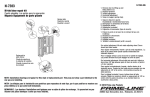
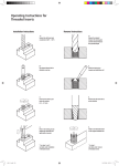
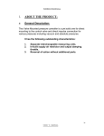
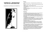
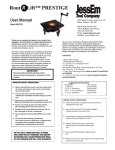
Quality Router Accessories OWNER’S MANUAL Deluxe Router Base Plate Model 3509 IMPORTANT Read and understand all safety guidelines and instructions carefully before operating. GENERAL INFORMATION You have purchased a ROUSSEAU CO. 3509 DELUXE ROUTER BASE PLATE. This plate is designed to make your router much more versatile whether you use it in a table or freehand. It offers removable insert rings for various sized bits and accepts standard 1-1/4” template guides. WARRANTY This product has a lifetime warranty to the original purchaser that applies to defects in materials and workmanship only. We will repair or replace the product or part(s) at our discretion. This warranty does not apply to product failure or defects due to direct or indirect misuse, abuse, negligence, accidents, alterations, repairs or lack of maintenance. The item must be shipped prepaid to our Clarkston, WA location. If items must be returned for warranty service, call to receive a Return Goods Authorization (RGA) number and further instruction. SAFETY GUIDELINES THIS SECTION CONTAINS IMPORTANT SAFETY INFORMATION CONCERNING A HAZARD THAT MAY CAUSE SERIOUS INJURY OR DEATH, and/or damage to stand or equipment if used improperly. Please read the following instructions very carefully. Always follow the safety recommendations and guidelines provided by the manufacturer of your router. When in doubt refer to your owner’s manual. Always wear eye protection. Failure to do so may cause severe injury and/or loss of sight. Always keep fingers clear of cutter. Failure to do so could result in serious injury or loss of fingers. Never wear loose clothing while operating equipment. It may become entangled in router bit causing severe injury or death. Always use guards and hold downs to protect you and your work piece. Operation without guards could result in loss of fingers, severe injury or death. PARTS INCLUDED 9” x 12” Phenolic Resin Base Plate Steel Starting Pin 4-1/16” Dia. Insert Ring 2-7/8” Dia. Insert Ring (4) Corner Snuggers™ w/ Hardware Leveling System Hardware TOOLS NEEDED Hand Drill or Drill Press Phillips Screw Driver 82° Countersink Bit Rubber Mallet Clamps (Wood Clamps or ‘C’ Clamps) Drill Bit (The Same Diameter As Your Mounting Screws) INSTALLING BASE PLATE INTO A BLANK TABLE TOP If you do not have our Base Plate Installation Kit (3509T), follow the instructions below. See back of this manual for more information on accessories. Cutting Thru Hole Straight 1x4 board or equal - Double Stick Taped or Clamped in 4 Places Outer Edge of Base Plate 9 8 32 3 8 Edge of Cutout Router Bit 9 11 32 Offset* Router Base Top To Be Routed Fig. 1 * (Base Diameter - Bit Diameter)/ 2 1. These directions assume your router has a 6 ½“ diameter base and a ½” router bit which creates a 3” offset. The ½” router matches the radius of the Base Plate. Other offsets = (Router Base Diameter –Bit Diameter)/2. 2. Set the Base Plate where you want it located on the table top and mark this location. The through hole will be ¾” smaller than the plate size. 3. Layout 4 straight 1 x 4’s or the equivalent as in Fig. 1 for router guides. 4. Cut the through hole following the guides with the router. An up cut spiral bit will minimize chip out. 5. Make sure smaller dimensions on Base Plate fits easily into through hole. Center Base Plate in through hole. Corner Snuggers can used to hold Base Plate in place. Cutting Rabbeted Edge Offset 9 Move All 4 Sides out 3/8" 12 Cut out dimensions x 1/4" deep 5/16" deep for Leveling system Router Base Top To Be Routed Fig. 2 6. Move guides out 3/8” to the offset (3” from the Base Plate for the 6 ½” router base). 7. Re-stick or re-clamp the guides and set router bit depth to 3/16”. 8. Rout out rabbet 3/8” wide x 3/16” deep following the guides with the ½” diameter bit. 9. Reset the router bit to ¼” if no leveling system will be used (lip of base plate is ¼” thick) or 5/16” if a leveling system will be used (clearance for the leveling system). Rout out rabbet to finished size. 10. Check hole for proper fit to base plate. Sand base plate or rout out a little more material until proper fit is obtained. INSTALLING LEVELING SYSTEM IN TABLE TOP After routing the baseplate hole into your table by following the Baseplate Installation Instructions or using the 3509-T Installation Template, proceed through the following steps to install the leveling system. 1. Mark the location for the six brass inserts. There will be one located in each corner and one on each long side of table top. Fig. A 2. Clamp a block of wood below the location of each hole to eliminate tear-out. Drill each hole using a 7/32” drill bit. Take care to assure that the holes are perpendicular to the tabletop. Fig. B 3. Press one insert into each hole from the top of the table until flush with the surface. This can be done by threading the insert onto the end of a 10-24 screw (the corner snugger mounting screws will work) and driving it gently with a hammer. Fig. C 4. Thread one nylon leveling screw into each insert from the bottom side of table. 5. Place baseplate into the table and adjust each leveling screw to desired height. Fig. D NOTE: The weight of the router should create sufficient resistance to hold leveling screws in place. However, more resistance can be achieved by distorting the leveling screw threads slightly using pliers. Fig. E Drill 6-7/32 Holes Centered In Routed Surface Fig. A Table Top Drill Into Wood Block To Prevent Fig. B Routed & Drilled Table Drive Insert Lightly With 10-24 Metal Screw & Fig. C Table Top Base Plate Leveling Fig. D Plyer Jaws Distort Thread with Plyer to Tighten Fig. E MOUNTING ROUTER TO BASE PLATE If you do not have our Base Plate Centering System, follow the instructions below. The router’s existing base plate will be your drilling jig. 1. Decide how you want the router positioned under the table. Things to consider are switch location, depth adjustment knobs, and the depth lock lever or knob. Large routers may need to be rotated so the handles fit through the opening at all depth settings (Fig. 3). Note: If mounting DeWalt DW621 follow instructions at the end of this section. 2. With your router in the inverted position and turned the direction you want it under the table, place a piece of tape on the front edge of its base plate to insure proper positioning. Remove your router’s base plate. 3. The top and front of the Rousseau base plate is determined by the location of the starting pin holes. These holes are to the right of the bit opening. Place a piece of tape front and center on the Rousseau base plate to keep things from getting turned around (Fig. 4). 4. Center your router’s baseplate on the nearest concentric ridge and if possible line up the mounting holes according to the radial lines. Use 3 or 4 pieces of tape to hold the base plate in position (Fig. 5). 5. Clamp the plates together with ‘C’ clamps or wood clamps. Do not use spring clamps, as they do not exert enough pressure and may allow the parts to move (Fig. 6). 6. Place a piece of scrap material under plate in drilling locations. Drill through back side the size of the holes in your router’s base plate. To achieve the straightest holes use a drill press at highest speed setting (Fig. 7). 7. Remove clamps, flip plate face up and countersink your mounting holes using 82° * countersink bit (Fig. 8). Mounting screws should sit just below flush. Note: For best results use a single flute countersink in a drill press at slow speed. 8. Mount the Rousseau base plate to the router (Fig. 9). If your router’s screws are not long enough, you can find longer screws at hardware stores, car or motorcycle parts departments or from Rousseau Co. * It is very important that you use the cor- rect angled countersink bit. To check, place screw tight against your bit. The angle of the screw head must line up with the angle of the bit (Fig. 10). When mounting the DeWalt DW621 line one edge up with the third concentric ring and the other with the tenth concentric ring (Fig. 11). Tape plate in position and follow steps 5-8 drilling out all 6 holes (4- 4mm and 2- 6mm). Fig. 11 SETUP Corner Snuggers™ are designed to tighten plate position by butting in to the 4 corners. They are not to designed to clamp the plate down to the table. 1.Once router is mounted, place plate in top open ing with starting pin holes to the right side. Assemble Corner Snuggers™ through plate using hardware provided (Fig. 12). 2.To hold plate in position push Corner Snuggers™ into all 4 corners and tighten. I N S E R T R I N G S : T h e i n sert rings are designed to snap together with a tight fit, so that they will stay securely in place. To remove and replace rings you may need to apply considerable force. We recommend tapping the rings gently but firmly using a soft mallet or piece of wood. If you desire a looser fit, you may lightly sand the inside diameter of the plate and red ring. When replacing red ring the tab on underside must line up with one of the two notches in plate. OPERATING INSTRUCTIONS To get the most versatility and safety from your router table we highly recommend our router fences (3301 Basic or 3301DL Deluxe). FREEHAND OPERATION: The starter pin is included for freehand routing of curved pieces, using a pilot bearing bit. Caution: Never rout freehand (w/out a fence) using a non-piloted bit. The starter pin may be used in one of the two predrilled locations in the mounting plate or three locations in the red ring. To store the starter pin use the predrilled hole in the back right of the mounting plate. When using the starter pin, the feed direction of the work piece is always right to left across the front of the bit. Set the work piece against the front of the starter pin and pivot it slowly into the bit. Once work piece has contacted the bit’s pilot bearing move it away from starter pin. While routing, make sure the work piece is always in contact 1392 Port Drive, Clarkston, WA 99403 800-635-3416 • 509-758-3954 • Fax 509-758-4991 email:[email protected] • www.rousseauco.com 3509 REV. 01-07