1
Model No.
TH-50LFB70U
TH-65LFB70U
TH-50LFB70E
TH-65LFB70E
TH-50LFB70W
TH-65LFB70W
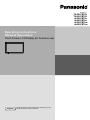
Operating Instructions
Network Operations
Touch Screen LCD Display (for business use)
English
Please read these instructions before operating your set
and retain them for future reference.
Contents
Before use
• Illustrations and screens in this Operating Instructions are images for illustration purposes, and may
be different from the actual ones.
• Descriptive illustrations in this Operating Instructions are created mainly based on the 50 inch model.
Read this first! · · · · · · · · · · · · · · · · · · · · · · · · · · · · · · · · · · · · · · · · · · · · · · · · · · ·
Request Regarding Security · · · · · · · · · · · · · · · · · · · · · · · · · · · · · · · · · · · · · · · · ·
What you can do · · · · · · · · · · · · · · · · · · · · · · · · · · · · · · · · · · · · · · · · · · · · · · · · ·
Notes on Using Wireless Connection · · · · · · · · · · · · · · · · · · · · · · · · · · · · · · · · · ·
Notes on Using Wired LAN · · · · · · · · · · · · · · · · · · · · · · · · · · · · · · · · · · · · · · · · · ·
Check your computerr · · · · · · · · · · · · · · · · · · · · · · · · · · · · · · · · · · · · · · · · · · · · · ·
3
5
6
7
8
9
Necessary environment for computers to be connected · · · · · · · · · · · · · · · · · · · · · · · · · · · · · 9
Connection · · · · · · · · · · · · · · · · · · · · · · · · · · · · · · · · · · · · · · · · · · · · · · · · · · · · 10
Example of Network Connection (Wired LAN) · · · · · · · · · · · · · · · · · · · · · · · · · · · · · · · · · · · · 10
Example of Network Connection (DIGITAL LINK) · · · · · · · · · · · · · · · · · · · · · · · · · · · · · · · · · · 11
Network Settings · · · · · · · · · · · · · · · · · · · · · · · · · · · · · · · · · · · · · · · · · · · · · · · · 12
Displaying the Network Settings menu · · · · · · · · · · · · · · · · · · · · · · · · · · · · · · · · · · · · · · · · ·
Wired LAN · · · · · · · · · · · · · · · · · · · · · · · · · · · · · · · · · · · · · · · · · · · · · · · · · · · · · · · · · · · · · · ·
Wireless LAN · · · · · · · · · · · · · · · · · · · · · · · · · · · · · · · · · · · · · · · · · · · · · · · · · · · · · · · · · · · · ·
Name Change · · · · · · · · · · · · · · · · · · · · · · · · · · · · · · · · · · · · · · · · · · · · · · · · · · · · · · · · · · · ·
Control I/F Select · · · · · · · · · · · · · · · · · · · · · · · · · · · · · · · · · · · · · · · · · · · · · · · · · · · · · · · · · ·
WEB Control · · · · · · · · · · · · · · · · · · · · · · · · · · · · · · · · · · · · · · · · · · · · · · · · · · · · · · · · · · · · ·
AMX D.D. · · · · · · · · · · · · · · · · · · · · · · · · · · · · · · · · · · · · · · · · · · · · · · · · · · · · · · · · · · · · · · · ·
Crestron Connected™ · · · · · · · · · · · · · · · · · · · · · · · · · · · · · · · · · · · · · · · · · · · · · · · · · · · · · ·
Network Status · · · · · · · · · · · · · · · · · · · · · · · · · · · · · · · · · · · · · · · · · · · · · · · · · · · · · · · · · · ·
Password · · · · · · · · · · · · · · · · · · · · · · · · · · · · · · · · · · · · · · · · · · · · · · · · · · · · · · · · · · · · · · · ·
Multi-Live· · · · · · · · · · · · · · · · · · · · · · · · · · · · · · · · · · · · · · · · · · · · · · · · · · · · · · · · · · · · · · · ·
Live mode Cut In · · · · · · · · · · · · · · · · · · · · · · · · · · · · · · · · · · · · · · · · · · · · · · · · · · · · · · · · · ·
DIGITAL LINK status · · · · · · · · · · · · · · · · · · · · · · · · · · · · · · · · · · · · · · · · · · · · · · · · · · · · · · ·
Digital Interface Box · · · · · · · · · · · · · · · · · · · · · · · · · · · · · · · · · · · · · · · · · · · · · · · · · · · · · · ·
DIGITAL LINK mode · · · · · · · · · · · · · · · · · · · · · · · · · · · · · · · · · · · · · · · · · · · · · · · · · · · · · · · ·
Extron XTP · · · · · · · · · · · · · · · · · · · · · · · · · · · · · · · · · · · · · · · · · · · · · · · · · · · · · · · · · · · · · ·
Reset · · · · · · · · · · · · · · · · · · · · · · · · · · · · · · · · · · · · · · · · · · · · · · · · · · · · · · · · · · · · · · · · · · ·
12
13
14
18
19
19
19
19
20
20
20
21
21
21
22
22
22
Connecting with Wired LAN · · · · · · · · · · · · · · · · · · · · · · · · · · · · · · · · · · · · · · · · 23
Computer operation· · · · · · · · · · · · · · · · · · · · · · · · · · · · · · · · · · · · · · · · · · · · · · · · · · · · · · · · 23
Connecting with Wireless LAN · · · · · · · · · · · · · · · · · · · · · · · · · · · · · · · · · · · · · · 23
Computer operation· · · · · · · · · · · · · · · · · · · · · · · · · · · · · · · · · · · · · · · · · · · · · · · · · · · · · · · · 23
Using Web Browser · · · · · · · · · · · · · · · · · · · · · · · · · · · · · · · · · · · · · · · · · · · · · · 24
Accessing from the Web browser · · · · · · · · · · · · · · · · · · · · · · · · · · · · · · · · · · · · · · · · · · · · · 24
Using Web Browser Control · · · · · · · · · · · · · · · · · · · · · · · · · · · · · · · · · · · · · · · · 34
PJLink™ Protocol · · · · · · · · · · · · · · · · · · · · · · · · · · · · · · · · · · · · · · · · · · · · · · · · 36
Trademarks · · · · · · · · · · · · · · · · · · · · · · · · · · · · · · · · · · · · · · · · · · · · · · · · · · · · 37
2
Read this first!
FCC and IC STATEMENT
This equipment has been tested and found to comply with the limits for an Other Class B digital device, pursuant to
Part 15 of the FCC Rules. These limits are designed to provide reasonable protection against harmful interference in
a residential installation. This equipment generates, uses and can radiate radio frequency energy and, if not installed
and used in accordance with the instructions, may cause harmful interference to radio communications. However,
there is no guarantee that interference will not occur in a particular installation. If this equipment does cause harmful
interference to radio or television reception, which can be determined by turning the equipment off and on, the user
is encouraged to try to correct the interference by one or more of the following measures:
• Reorient or relocate the receiving antenna.
• Increase the separation between the equipment and receiver.
• Connect the equipment into an outlet on a circuit different from that to which the receiver is connected.
• Consult the Panasonic Service Center or an experienced radio/Display technician for help.
FCC Caution:
To assure continued compliance, follow the attached installation instructions and use only shielded
interface cables when connecting to peripheral devices. Any changes or modifications not expressly
approved by Panasonic Corp. of North America could void the user’s authority to operate this device.
FCC and Industry Canada (IC) RF Exposure Warning:
• This Display is provided with built-in transmitter: Wireless LAN Adapter with FCC ID:
H8N-WLU5150/IC ID:1353A-WLU5150;
• This transmitter complies with FCC and IC radiation exposure limits set forth for an uncontrolled
environment for mobile use with minimum 8 inches (20 cm) spacing requirement between transmitter
and all person’s body (excluding extremities of hands, wrist and feet) during wireless modes of
operation.
• Other third-party wireless transmitters should not be used as they have not been RF exposure
evaluated for use with this Display and may not comply with RF exposure requirements.
<Only for wireless LAN if capable of transmission in the 5.15 ~ 5.25 GHz frequency band>
This product is restricted to indoor use due to its operation in the 5.15 to 5.25 GHz frequency range.
FCC and IC require this product to be used indoors for the frequency range 5.15 to 5.25 GHz to reduce the
potential for harmful interference to co-channel Mobile Satellite systems. High power radars are allocated as
primary users of the 5.25 to 5.35 GHz and 5.65 to 5.85 GHz bands. These radar stations can cause interference
with and/or damage this product.
FCC Declaration of Conformity
Model:
TH-50LFB70U, TH-65LFB70U
Responsible Party: Panasonic Corporation of North America
Two Riverfront Plaza, Newark, NJ 07102-5490
Contact Source:
Panasonic System Communications Company
of North America
1-877-655-2357
This device complies with Part 15 of the FCC Rules and all applicable IC RSS standards.
Operation is subject to the following two conditions:
(1) This device may not cause harmful interference, and (2) this device must accept any interference received,
including interference that may cause undesired operation.
3
Read this first!
LCD Display
Declaration of Conformity (DoC)
“Hereby, Panasonic Corporation declares that this Display is in compliance with the essential
requirements and other relevant provisions of the Directive 1999/5/EC.”
If you want to get a copy of the original DoC of this Display, please visit the following website:
http://www.doc.panasonic.de
Authorized Representative:
Panasonic Testing Centre
Panasonic Marketing Europe GmbH
Winsbergring 15, 22525 Hamburg, Germany
This Display is intended to be used in the following countries.
Albania, Austria, Belgium, Bulgaria, Cyprus, Czech Republic, Denmark, Estonia, Finland, France,
Germany, Greece, Hungary, Italy, Iceland, Latvia, Lithuania, Luxembourg, Malta, Netherlands, Norway,
Poland, Portugal, Romania, Slovakia, Slovenia, Spain, Sweden, Switzerland, Turkey, United Kingdom
The wireless LAN feature of this Display shall exclusively be used inside buildings.
UAE
Singapore
UAE-TRA
REGISTERED No:
ER0081229/12
DEALER No:
DA0052708/10
Complies with
IDA Standards
DB01017
Thailand
“เครื่ องโทรคมนาคมและอุปกรณ์น้ ีมีความสอดคล้องตาม
มาตรฐานทางเทคนิค เลขที่ กทช. มท. 1012-2551”
■ About built-in wireless LAN
CAUTION:
Be aware of the following limits before using the Wireless LAN Module.
● To use the Wireless LAN Module, an access point needs to be obtained.
● Do not use the Wireless LAN Module to connect to any wireless network (SSID*) for which you do not have
usage rights. Such networks may be listed as a result of searches. However, using them may be regarded as
illegal access.
*SSID is a name for identifying a particular wireless network for transmission.
● Do not subject the Wireless LAN Module to high temperatures, direct sunlight or moisture.
● Do not bend, or subject the Wireless LAN Module to strong impacts.
● Do not disassemble or alter the Wireless LAN Module in any way.
● Do not attempt to install the Wireless LAN Module in any incompatible device.
● Do not remove the Wireless LAN Module from the host product during operations.
● Data transmitted and received over radio waves may be intercepted and monitored.
● To avoid malfunctions caused by radio wave interface, keep the host product away from the devices such as
other wireless LAN devices, microwaves and the devices that use 2.4 GHz and 5 GHz signals when using the
Wireless LAN Module.
● When noises occur due to the static electricity, etc., the host product might stop operating for the protection of
the devices. In this case, turn the host product Off with Mains power On / Off switch, then turn it On again.
● Depending on the area, this Wireless LAN Module may not be available.
4
Request Regarding Security
When using this product, security breaches of the type described below are conceivable.
• Leakage of your private information via this product
• Illegal operation of this product by a malicious third-party
• Harm to or cessation of operation of this product by a malicious third-party
Be sure to implement sufficient security measures.
•
•
•
•
•
Set passwords, and limit the users that are permitted login access.
Make sure the password is as hard to guess as possible.
Change the password periodically.
Panasonic Corporation and its affiliated companies never directly ask customers for their password. Do not give
out your password even if directly asked by a third-party representing themselves as Panasonic Corporation.
Always use on a network that has safety protection such as a firewall implemented.
About Wireless LANs
The advantage of a wireless LAN is that information can be exchanged between a PC or other such equipment and an
access point using radio waves as long as you are within range for radio transmissions.
On the other hand, because the radio waves can travel through obstacles (such as walls) and are available everywhere
within a given range, problems of the type listed below may occur if security-related settings are not made.
• A malicious third-party may intentionally intercept and monitor transmitted data including the content of e-mail and
personal information such as your ID, password, and/or credit card numbers.
• A malicious third-party may access your personal or corporate network without authorization and engage in the
following types of behavior.
Retrieve personal and/or secret information (information leak)
Spread false information by impersonating a particular person (spoofing)
Overwrite intercepted communications and issue false data (tampering)
Spread harmful software such as a computer virus and crash your data and/or system (system crash)
Since most wireless LAN adapters or access points are equipped with security features to take care of these problems,
you can reduce the possibility of these problems occurring when using this product by making the appropriate security
settings for the wireless LAN device.
Some wireless LAN devices may not be set for security immediately after purchase. To decrease the possibility of
occurrence of security problems, before using any wireless LAN devices, be absolutely sure to make all security-related
settings according to the instructions given in the operation manuals supplied with them.
Depending on the specifications of the wireless LAN, a malicious third-party may be able to break security settings by
special means.
Please contact Panasonic if you need help taking care of security settings or other such.
If you cannot perform security settings for your wireless LAN by yourself, please contact the Panasonic Support Center.
Panasonic asks customers to thoroughly understand the risk of using this product without making security settings, and
recommends that the customer make security settings at their own discretion and responsibility.
5
What you can do
This unit supports wired LAN and wireless LAN enabling the network functions as below.
<WEB Control> (See page 19)
The following operations are possible when using Web Browser.
• Setting and adjusting the Display
• Displaying the Display status
<PJLink> (See page 36)
Compatible with PJLink Class 1. The following operations can be performed from a computer when PJLink protocol
is used.
• Setting the Display
• Querying the Display status
<Command control>
Network function of the unit can control the unit in the same way as serial control from a network.
Supported commands
Commands used in the serial control are supported. (See “Operating Instructions, Display Operations”)
• When using [WEB Control], [PJLink] and [Command control], enable LAN in [Control I/F Select] and [DIGITAL LINK
mode] in the [Network Settings] menu, and set [WEB Control] to [On]. (See pages 19 and 22)
• When using [WEB Control] wirelessly, enable wireless LAN in [Wireless LAN], and set [WEB Control] to [On].
(See pages 14 to 15)
Manager (Windows/Mac)
● Wireless
Software for sending the computer screen via wireless/wired LAN.
To use this function, a specialized software is required. Please install this software from the supplied CD-ROM.
This unit does not support the following functions.
Virtual remote control function
USB display function
Display for iOS (Panasonic Wireless Projector for iOS)
● Wireless
Software for sending PDF files/JPEG images etc. saved in an iPad/iPhone/iPod touch to this unit via wireless
LAN (Wi-Fi).
For more information, see the website below. (Wireless Display for iOS)
http://panasonic.net/prodisplays/download/software/index.html
6
Notes on Using Wireless Connection
Wireless connection function of the Display uses radio waves in the 2.4 GHz and 5 GHz bands.
A radio station license is not required, but be sure to read and fully understand the following items before use.
■ Do not use near other wireless equipment.
The following equipment may use radio waves in the same band as the Display.
When the Display is used near these devices, radio wave interference may make communication impossible, or the
communication speed may become slower.
• Microwave ovens, etc.
• Industrial, chemical and medical equipment, etc.
• In-plant radio stations for identifying moving objects such as those used in factory manufacturing lines, etc.
• Designated low-power radio stations
■ If at all possible, avoid the use of cellular phones, TV sets or radios near the Display.
Cellular phones, TV sets, radios and similar devices use different radio bands from the Display, so there is no effect on
wireless communication or the transmission and reception of these devices. However, radio waves from the Display may
produce audio or video noise.
■ Wireless communication radio waves cannot penetrate steel reinforcements, metal, concrete,
etc.
Communication is possible through walls and floors made from materials such as wood and glass (except glass containing
wire mesh), but not through walls and floors made from steel reinforcements, metal, concrete, etc.
■ Avoid using the Display in locations prone to static electricity.
If the Display is used in a location prone to static electricity, such as on a carpet, the wireless LAN or wired LAN connection
may be lost.
If this happens, eliminate the source of static electricity or electromagnetic noise and reconnect to the wireless LAN or
wired LAN.
■ Using the Display outside the country
It is forbidden to take the Display outside the country or region where you purchased it, so use it only in the said country or
region. Also, note that depending on countries or regions there are restrictions on the channels and frequencies at which
you can use the wireless LAN.
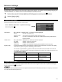
■ Available wireless LAN channels
The channels (frequency range) that can be used differ according to the country or region. Refer to the table below.
Country or region
Global
Standard
Channels used
Frequency band (Center frequency)
IEEE802.11a/n
Passive scanning
5.180 GHz - 5.825 GHz
IEEE802.11b/g/n
Passive scanning
2.412 GHz - 2.472 GHz
¼ The frequency and channel differ depending on the country.
¼ The passive scanning is performed by changing radio to the channel being scanned in each country.
¼ Please use the wireless LAN feature in compliance with the laws of each country.
■ For Mexico:
Operation of this equipment is subject to the following two conditions:
(1) this equipment might not have a harmful interference and
(2) this equipment must accept any interference, including one that might cause it to malfunction
■ For Jamaica:
• This product contains Type Approved Modules by Jamaica.
7
Notes on Using Wired LAN
Use straight or crossover LAN cable that is compatible with category 5 or above.
¼ Whether straight cable, crossover cable or both can be used varies depending on the system configuration. For details,
consult your system administrator.
When setting up the Display at a place, where electric statistic occurs often, take a sufficient anti-static measure before
start using.
¼ When the Display is used at a location, where static electricity occurs often, such as on a carpet, communications of
the DIGITAL LINK and the wired LAN are disconnected more often. In that case, remove static electricity and the noise
source that may cause problems with an antistatic mat, and re-connect the DIGITAL LINK and the wired LAN.
¼ In rare cases, the LAN connection is disabled due to static electricity or noise. In that case, turn off the power of the
Display and the connected devices once and then re-turn on the power. Connect the DIGITAL LINK and the LAN.
The Display may not work properly due to strong radiowave from the broadcast station or the radio.
¼ If there is any facility or equipment, which outputs strong radiowave, near the installation location, set up the Display
at a location sufficiently far from the source of the radiowave. Or, wrap the LAN cable connected to the DIGITAL LINK
terminal by using a piece of metal foil or a metal pipe, of which is grounded at both ends.
8
Check your computer
Necessary environment for computers to be connected
• First, check your computer to see whether or not it has a wired LAN or a built-in wireless LAN function.
• Before connecting the Display to the computer, be sure to check the following settings.
• Operation is not guaranteed for all wireless LAN adapters and built-in wireless LAN adapters.
■ Wired LAN
For LAN cable
Is the cable properly connected?
Use LAN cable that is compatible with category 5 or above.
Check 1
•
•
Wired LAN settings
<Computer with a built-in wired LAN function>
• Is your wired LAN switched on?
<Computer without a built-in wired LAN function>
• Is your wired LAN adapter properly recognized?
• Is your wired LAN adapter switched on?
• Install the wired LAN adapter driver beforehand.
For details on how to install the driver, refer to the instructions accompanying the wired LAN adapter.
Check 2
■ Wireless LAN
Wireless LAN settings
<Computer with a built-in wireless LAN function>
• Is your wireless LAN switched on?
<Computer without a built-in wireless LAN function>
• Is your wireless LAN adapter properly recognized?
• Is the wireless LAN adapter switched on?
• Install the wireless LAN adapter driver beforehand.
For details on how to install the driver, refer to the instructions accompanying the wireless card.
Check 1
Check 2
Computer’s settings
• When security (firewall) software and utilities for network cards are installed, these may prevent connection of
the Display.
<Windows XP/Windows Vista/Windows 7/Windows 8>
• Is Network Bridge enabled?
• Has your firewall been disabled?
■ For Web Browser
• Web Browser is necessary to use WEB control.
• Compatible OS : Windows XP/Windows Vista/Windows 7/Windows 8, Mac OS X v10.4/v10.5/v10.6,
•
OS X v10.7/v10.8
Compatible Web Browser : Internet Explorer 7.0/8.0/9.0/10.0, Safari 4.x/5.x/6.x (Mac OS)
9
Connection
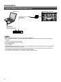
Example of Network Connection (Wired LAN)
COMPUTER
Display (main unit, rear)
LAN cable
(not supplied)
LAN cable
(commercial)
Hub or broadband router
• Make sure the broadband router or hub supports 100BASE-TX.
• Use a LAN cable between the twisted pair cable transmitter and the device that conforms to the following
conditions.
• It meets or exceeds CAT5e standards
• It is a shielded cable (with a connector)
• It is a straight cable
• It is a single wire
• When laying the cable(s), use an instrument such as a cable tester or cable analyzer and check whether the
cable characteristics are CAT5e or above.
• Touching the LAN terminal with a statically charged hand (body) may cause damage due to its discharge.
Do not touch the LAN terminal or a metal part of the LAN cable.
• For instructions on how to connect, consult your network administrator.
10
Connection
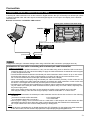
Example of Network Connection (DIGITAL LINK)
A twisted pair cable transmitter such as the Panasonic Digital Interface Box (ET-YFB100G) uses twisted pair cables
to transmit inputted video and audio signals, and these digital signals can be input to the Display via the DIGITAL
LINK terminal.
Network connections via DIGITAL LINK terminal
Display (rear surface of the main body)
PC
DIGITAL LINK terminal
LAN cab
cable
(not supp
upplied)
When a Panasonic ET-YFB100G is used
LAN cable
(commercial)
L
LAN
cable
(commercial)
Hub or broadband router
Configure the settings in “Network Settings when using a DIGITAL LINK connection. (see pages 20 to 22)
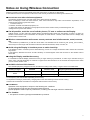
Precautions for use while connecting with a twisted pair cable transmitter
Installing
g / Connecting
g
● Ask the dealer or a qualified technician to carry out the cable wiring work for DIGITAL LINK connections.
Insufficient wiring work may cause the inability to apply the cable transmission characteristics and cropped
or fuzzy images and sounds.
● The transmission distance between the twisted pair cable transmitter and the device is up to 100 meters.
Exceeding this distance can cause cropped images or sounds, as well as LAN communication errors.
● Do not use a hub between the twisted pair cable transmitter and the Display.
● When connecting to the Display using the twisted pair cable transmitter (receiver) of other maker, do not
use another twisted pair cable transmitter between the twisted pair cable transmitter of other maker and
this device. The images and sounds may be interrupted or become unstable.
● If possible, lay the cable so that it is extended and not coiled in order to minimize both external and internal noise.
● Lay out cables of the twist pair cable transmitter and this product away from other cables, especially from
the power supply cable.
● When laying multiple cables, keep them as close together as possible running parallelly and not bundled.
● After laying the cable(s), make sure that the signal quality in “DIGITAL LINK status” is -12 dB or below.
Twisted pair
p cables
● Use a LAN cable between the twisted pair cable transmitter and the device that conforms to the following
conditions.
● It is a straight cable
● It meets or exceeds CAT5e standards
● It is a solid cable
● It is a shielded cable (with a connector)
● When laying the cable(s), use an instrument such as a cable tester or cable analyzer and check whether the cable
characteristics are CAT5e or above. When using a relay connector along the path, also include this in the measurements.
● Do not pull cables hard. Also avoid forcefully bending or folding them.
Other
● This device is compatible with our Digital Interface Box (ET-YFB100G). For the twisted pair cable transmitter
of the other maker, see the website: http://panasonic.net/prodisplays/support/digitallink.html
11
Network Settings
Make the various settings to use the network function.
For network settings, contact your network administrator.
Concerning the touch operation, see “Operating Instructions, Display Operations”.
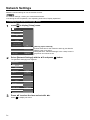
Displaying the Network Settings menu
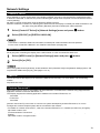
1
Press
to display [Setup] menu.
Setup
Touch Screen Settings
MULTI PIP Settings
Network Settings
Memory Viewer Settings
Signal
Screensaver
ECO Mode settings
Input label
Function Button Settings
On/Off Timer Settings
Day/Time Settings
Component/RGB-in select
Monitor Out
Off
No activity power off
Menu Display Duration
2
RGB
Disable
30 S
OSD Brightness
5
OSD Language
English (UK)
[Starting up the network]
It takes some time for the network to start up just after the
Display power is turned on.
During that time, “Network Settings” in the “Setup” menu is
grayed out and cannot be set.
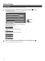
Select [Network Settings] with the ▲▼ and press
The [Network Settings] menu appears.
Network Settings
Network
Wired LAN
Wireless LAN
Name Change
Control I/F Select
RS-232C
WEB Control
On
AMX D.D.
Off
Crestron Connected™
Off
Network Status
Panasonic APPLICATION
Password
Multi-Live
Live mode Cut In
Off
DIGITAL LINK
DIGITAL LINK status
Digital Interface Box
DIGITAL LINK mode
Auto
Extron XTP
Off
Reset
3
12
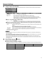
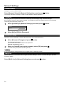
Press ▲▼ to select the item and set with ◄►.
Press
to display sub menu.
button.
Network Settings
Wired LAN
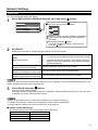
You can make detailed wired LAN settings.
1
Select [Wired LAN] in [Network Settings] menu and press
Wired LAN
1
Save
button.
IP address
Off
DHCP
IP address
192.168. 10.100
Subnet mask
255.255.255. 0
Gateway
Select the item and press
button.
000.192.168.010
192.168. 0. 1
1
2
3
All delete
4
5
6
Delete
7
8
9
0
.
Ok
Cancel
Delete the current numbers. ([Delete] or [All delete])
Enter numbers and dots using numeric keypad on
the screen.
4 Select [Ok] and press
button.
To cancel changing the address, select [Cancel]
and press
button.
2
3
2
Set [DHCP].
When [Off] is selected, IP address and other settings can be set manually.
DHCP
(DHCP client function)
IP address
On:
If a DHCP server exists in the network to which the display
is connected, the IP address will automatically be acquired.
Off:
If a DHCP server does not exist in the network to which the
display is connected, additionally set [IP address], [Subnet
mask] and [Gateway].
Enter the IP address if DHCP server is not used.
(Display of IP address and setting)
Subnet mask
(Displaying and setting the subnet mask)
Gateway
(Display of gateway address and setting)
If not using a DHCP server, enter the subnet mask.
Enter the gateway address if DHCP server is not used.
If [DHCP] is set to [On], the IP address and other items are not displayed. Check the [Network Status] page for the
current IP address and other items. (See page 20)
3
Select [Save] and press
button.
Save the current network settings.
If message indicating a duplicate IP address is displayed in [Network Status] (see page 20), check the same
IP address is not used within the same network.
• Before using the DHCP server, make sure the DHCP server is already functioning.
• For details of IP address, subnet mask, and gateway, ask the network administrator.
• A wired LAN and wireless LAN cannot be used in the same segment.
■ Default wired LAN settings
The following settings are set before the Display leaves the factory.
DHCP
IP address
Subnet mask
Gateway
Off
192.168.10.100
255.255.255.0
192.168.10.1
13
Network Settings
Wireless LAN
You can make detailed wireless LAN settings. (You cannot select AD HOC mode with this display.)
Setting network number
1
2
Select [Wireless LAN] in [Network Settings] menu and press
Select the number to be connected for
[Wireless LAN].
• [Off], [S-DIRECT], [M-DIRECT], [USER1]-[USER3]
button.
Wireless LAN
Save
Wireless LAN
Off
• Selecting [Off] disables the wireless LAN.
• Network number: [S-DIRECT] is available only when connecting via wireless LAN with the application software
the “Wireless Manager”. For details, refer to the operation manual of the “Wireless Manager”.
• Displays that can be connected to [S-DIRECT] or [M-DIRECT] are up to 10.
You can configure more precise network settings, if you select [M-DIRECT] or [USER1] - [USER3] (user) for [Wireless LAN].
Configuration of Wireless LAN [M-DIRECT]
Even if there is no access point, you can still connect the Display to computer via the infrastructure. In addition, the
connection with the iPad / iPhone / iPod touch is much easier.
For more information, see the website below.
http://panasonic.net/prodisplays/download/software/index.html
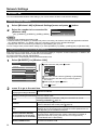
1
Select [M-DIRECT] for [Wireless LAN].
Wireless LAN
1
Save
Wireless LAN
Select the item and press
button.
IP address
M-DIRECT
000.192.168.010
192.168. 10.100
IP address
Subnet mask
255.255.255. 0
SSID
Channel
Key
2
3
All delete
4
5
6
Delete
7
8
9
0
.
Ok
Cancel
1
Delete the current numbers. ([Delete] or [All delete])
Enter numbers and dots using numeric keypad on
the screen.
4 Select [Ok] and press
button.
To cancel changing the address, select [Cancel] and
press
button.
2
3
********
Wireless Network Standby
Wireless WEB Control
2
1
Press ▼ to go to the next item.
IP address
(Displaying and setting the IP address)
Subnet mask
(Displaying and setting the subnet mask)
Enter the IP address.
Enter the subnet mask.
SSID
Select [M-DIRECT] in [Wireless LAN], then the SSID can be set.
Entering characters
page 18
Channel
Select [M-DIRECT] in [Wireless LAN], then the Channel can be set.
Select a channel for the access point ( page 8).
Select [M-DIRECT] in [Wireless LAN], then the Key can be set
Setting a key for the access point. Input either 8 to 63 alphanumerics or
a 64 digit string in the hexadecimal format.
Set to [On] when using wireless web control or command control to turn
Wireless Network Standby
the power off/on. When set to [On], power consumption in standby is
(for TH-50LFB70U, TH-65LFB70U,
higher than when set to [Off]. (This function is not supported by
TH-50LFB70W and TH-65LFB70W)
TH-50LFB70E and TH-65LFB70E.)
Set to [On] when controlling the display from a web browser on a PC
Wireless WEB Control
connected via wireless LAN.
Key
14
Network Settings
3
Select [Save] and press
button.
Save the current network settings.
■ Default settings of [M-DIRECT]
The following settings as [M-DIRECT] in the [Wireless LAN] are set before the Display leaves the factory.
IP address
Subnet mask
SSID
Channel
Key
Wireless Network
Standby
Wireless WEB Control
•
•
•
•
192.168.12.100
255.255.255.0
M-DIRECT + The last 4 digits of the Display ID
1
The same string as the SSID
Off (for TH-50LFB70U, TH-65LFB70U,
TH-50LFB70W and TH-65LFB70W)
Off
The authentication method is WPA2-PSK, and the encryption method is AES. Both methods are fixed.
When you need to change initial configuration of [M-DIRECT], please contact your network administrator.
Make sure the initial Key is changed for safety.
As the DHCP server is already functioning, select [ON] before connecting a computer.
Configuration of Wireless LAN [USER1] - [USER3]
1
Select [USER1] – [USER3] for [Wireless LAN].
Wireless LAN
1
Save
button.
IP address
Wireless LAN
USER1
000.192.168.11
Name Change
Off
DHCP
1
2
3
All delete
4
5
6
Delete
7
8
9
.
IP address
192.168.11.100
0
Subnet mask
255.255.255. 0
Ok
Gateway
192.168.11.1
SSID
2
Select the item and press
2
3
4
Cancel
Delete the current numbers. ([Delete] or [All delete])
Enter numbers and dots using numeric keypad on the screen.
Select [Ok] and press
button.
To cancel changing the address, select [Cancel] and
press
button.
Set [DHCP].
When [Off] is selected, IP address and other settings can be set manually.
Name Change
DHCP
(DHCP client function)
IP address
(Display of IP address and setting)
You can change the user name. Entering characters
page 18
On:
If a DHCP server exists in the network to which the display is
connected, the IP address will automatically be acquired.
Off: If a DHCP server does not exist in the network to which the
display is connected, additionally set [IP address], [Subnet mask]
and [Gateway].
Enter the IP address if DHCP server is not used.
Subnet mask
(Displaying and setting the subnet mask) If not using a DHCP server, enter the subnet mask.
Gateway
(Display of gateway address and setting) Enter the gateway address if DHCP server is not used.
• If [DHCP] is set to [On], the IP address and other items are not displayed. Check the [Network Status] page for
the current IP address and other items. (See page 20)
• Before using the DHCP server, make sure the DHCP server is already functioning.
• For details of IP address, subnet mask, and gateway, ask the network administrator.
• A wired LAN and wireless LAN cannot be used in the same segment.
15
Network Settings
3
Press ▼ to go to the next item.
Make the settings related to the wireless connection between the Display and the network.
SSID
Authentication
Open
Encryption
None
● SSID
: Enter the SSID registered at the access point.
Entering characters
page 18
• SSID has to be entered in alphanumeric letters.
• You cannot set “any” or “ANY” for SSID.
● Authentication
: Set the user authentication method used by the network to be connected.
Open
: Select when the access point authentication method is OpenSystem.
Shared
WPA-PSK
WPA2-PSK
WPA-EAP/
WPA2-EAP
WPA-EAP
WPA2-EAP
: Select when the access point authentication method is Shared Key.
● Encryption
None
WEP
TKIP
AES
: Select the encryption method to be used for communication between the
Display and the network.
: Select when transmit without encryption. It is selectable only when
[Authentication] is [Open] or [Shared].
: Select when Encryption is WEP.
: Select when Encryption is TKIP.
Selectable when [Authentication] is either [WPA-PSK], [WPA2-PSK],
[WPA-EAP], [WPA2-EAP].
: Select when Encryption is AES.
Selectable when [Authentication] is either [WPA-PSK], [WPA2-PSK],
[WPA-EAP], [WPA2-EAP].
Important video/audio data is protected because AES encryption programming takes place in advance for
all network numbers, even if [Encryption] is set to [None].
16
Network Settings
4
Press ▼ to go to the next item.
In addition, further perform the following setting depending on [Authentication] and [Encryption] settings.
Default Key
Key 1
1
*******
Key 2
*******
Key 3
*******
Key 4
*******
● method:
Default Key
Key1 – 4
: Set 1 – 4 numerals for the default key.
: Set a WEP key to the key number selected with [Default Key].
Either the 64-bit or 128-bit WEP key can be set. For the 64-bit key, input five
alphanumerics (or a 10-digit string for the hexadecimal format) for the 128-bit key,
input 13 alphanumerics (or a 26-digit string for the hexadecimal format).
● When using [WPA-PSK] or [WPA2-PSK] :
Set a key.
Input either 8 to 63 alphanumerics or a 64 digit string in the hexadecimal format.
● When the authentication method is [WPA-EAP/WPA2-EAP], [WPA-EAP], [WPA2-EAP]:
Set [EAP], [User name], and [Password].
EAP:
Select the EAP setup in the RADIUS server. Types of EAP that can be selected are as
follows.
PEAP (MS-CHAPv2), PEAP (GTC), EAP-TTLS (MD5),
EAP-TTLS (MS-CHAPv2), EAP-FAST(MS-CHAPv2), EAP-FAST(GTC)
User name:
Input a user name used for authentication (excluding spaces)(maximum 64 characters).
Password:
Input a password used for authentication (maximum 64 characters).
Entering characters
page 18
• If you are unable to connect to the wireless LAN through the access point, contact the manufacturer of
•
•
5
the access point.
When using EAP, the display needs to be set according to the setting of the RADIUS server. Check with
the network administrator for the setting of the RADIUS server.
When using an EAP together with an access point with invalid SSID broadcast, select WAP-EAP or
WAP2-EAP for the authentication method even if the authentication method of the access point is WPAEAP/WPA2-EAP.
Select [Save] and press
button.
Save the current network settings.
■ Default settings of [USER1] - [USER3]
The following settings as [USER1] - [USER3] in the [Wireless LAN] are set before the Display leaves the
factory.
SSID
DHCP
IP address
Subnet mask
Gateway
Panasonic Display
Off
192.168.11.100
255.255.255.0
192.168.11.1
Authentication
Encryption
Open
None
17
Network Settings
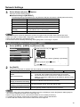
Name Change
You can change the Display name to be displayed on the network.
1
Select [Name Change] in [Network Settings] menu and press
button.
The keyboard is displayed.
Up to 8 characters can be entered for the Display name.
Name Change
Name0000█
A B C
N O P
a b c
n o p
0 1 2
!
” #
_ `
|
D
Q
d
q
3
$
~
E
R
e
r
4
%
<
Ok
F
S
f
s
5
&
>
G
T
g
t
6
’
(
H
U
h
u
7
)
I
V
i
v
8
+
[
J
W
j
w
9
–
]
K
X
k
x
L M
Y Z
l m
y z
Space
/ = ?
{
}
,
Cancel
All delete
Delete
@
.
\
;
ˆ
:
1 select
2 set
[Entering characters]
To enter text, select characters in the on-screen keyboard.
Example: Specifying “LCD 01”
1 Select “All delete”.
Name0000Ű
All text is deleted.
To delete individual characters, select “Delete”.
2 Select “L”.
L█
Repeat this process to enter the next character.
3 Select “C” and “D”.
LCD█
4
Select “Space”.
LCD
5
█
Select “0” and “1”.
LCD 01█
2
18
When you finished entering the Display name, select [Ok] and press
To cancel saving the Display name, select [Cancel].
.
Network Settings
Control I/F Select
Select whether to control via RS-232C of the Display's SERIAL terminal or with the DIGITAL LINK/LAN terminal.
If “DIGITAL LINK/LAN” is selected, the power indicator lights orange when the power is turned off with the remote
control (standby).
RS-232C: Controls via RS-232C using the Display's SERIAL terminal.
DIGITAL LINK/LAN: Controls via LAN using the LAN terminal of the Display or twisted pair cable transmitter or via
RS-232C using the SERIAL (RS-232C) terminal of twisted pair cable transmitter.
1
2
●
●
Select [Control I/F Select] in [Network Settings] menu and press
button.
Select [RS-232C] or [DIGITAL LINK/LAN].
If “RS-232C” is selected, HDMI communication via twisted pair cable transmitter becomes possible.
For the case of “DIGITAL LINK/LAN”, see “DIGITAL LINK mode” (see page 22).
WEB Control
Set to [On] when controlling the display from a web browser on a PC connected via wired LAN.
1
2
Select [WEB Control] in [Network Settings] menu and press
button.
Select [On] or [Off].
When using [WEB Control] wirelessly, enable wireless LAN in [Wireless LAN] in the [Network Settings] menu, and
set [Wireless WEB Control] to [On]. (See pages 14 to 15)
AMX D.D.
This function allows the Display to be detected by AMX Device Discovery. For more details, visit the following
website.
http://www.amx.com/
Crestron Connected™
When this function is set to on, the Display can be monitored or controlled via the network using equipment and
application software of Crestron Electronics, Inc.
This Display supports the following application software from Crestron Electronics, Inc.
● RoomView® Express
● Fusion RV®
● RoomView® Server Edition
[Crestron Connected™] is a function to connect to a system developed by Crestron Electronics, Inc. which
manages and controls multiple system devices connected to the network.
• For details of “Crestron Connected™”, refer to the Crestron Electronics, Inc. website (Provided only in English).
http://www.crestron.com/
For the download of “RoomView® Express”, refer to the Crestron Electronics, Inc. website (Provided only in
English).
http://www.crestron.com/getroomview
19
Network Settings
Network Status
Displays the current network status.
Select [Network Status] in [Network Settings] menu and press
button.
The Display information, settings of wired LAN and wireless LAN are displayed.
Password
Set to [On] to perform password check when connecting with the Display using “Wireless Manager”.
By controlling connection with password setting, it is possible to prevent an external device from accidentally
connecting and interrupting images, etc.
1
Select [Password] in [Network Settings] menu and press
button.
Password
Password
Off
Password Change
2
Select [On] or [Off] for [Password].
Password Change
Password can be registered or changed. No password is set in the default setting.
1
Select [Password Change] and press
button.
The keyboard is displayed.
Up to 8 characters can be entered for the password.
Entering characters
page 18
2
When you finished entering the password, select [Ok] and press
.
To cancel saving the password, select [Cancel].
It is recommended to change password on a regular basis for keeping it private.
Multi-Live
Switch to the MULTI-LIVE mode when using the “Wireless Manager”. See the “Wireless Manager” operation
manual for details.
Select [Multi-Live] in [Network Settings] menu and press
20
button.
Network Settings
Live mode Cut In
Set this [ON] to allow interrupt of the Live mode by other users while the Live mode is active (sending image) by the
“Wireless Manager”. For details, refer to “Wireless Manager” operating manual.
1
2
Select [Live mode Cut In] in [Network Settings] menu and press
button.
Select [On] or [Off].
DIGITAL LINK status
Display the DIGITAL LINK connection environment.
DIGITAL LINK status
Select “DIGITAL LINK status” in [Network Settings]
menu, and press
LINK status
HDMI status
Signal quality
.
LINK status
No Link
HDMI status
No HDMI
Signal Quality
Minimum
-XX dB
Maximum
-YY dB
: Either “No link”, “DIGITAL LINK”, or “Ethernet” will be displayed.
No link
: No LAN connection, etc.
DIGITAL LINK
: Connected to the DIGITAL LINK device by LAN
Ethernet
: The PC is connected to the DIGITAL LINK terminal of this product and is
LAN connected
: Either “No HDMI”, “HDMI ON”, or “HDCP ON” will be displayed.
No HDMI
: DIGITAL LINK not connected
HDMI ON
: DIGITAL LINK connected
HDCP ON
: A signal with an HDCP is flowing with a DIGITAL LINK connection.
: It is the quantified minimum and maximum numbers of errors that have occurred. The display
colors are red, yellow, or green, depending on the number.
The number is represented by yellow or red if the LAN cable is disconnected or the cable is
not shielded. This signal quality shows figures between the twisted pair cable transmitter that is
connected and the display.
Signal Quality
Display Colors
Reception Status
-12dB or below
Green
The reception is normal
-11 to -8dB
Yellow
Part of the received
data is corrupted
-7dB or above
Red
There are reception
difficulties
Digital Interface Box
A switch will be made to the Set up Digital Interface Box menu when “Digital Interface Box” in [Network Settings]
menu is selected and
is pressed.
This function can only be selected when the Digital Interface Box (ET-YFB100G) made by our company is connected
to a LAN terminal and its power is on.
21
Network Settings
DIGITAL LINK mode
You can switch the setting of DIGITAL LINK/LAN terminal.
LAN: Enables LAN communication via the Display's LAN terminal.
Auto (LAN): Enables automatic selection between LAN communication via the Display's LAN terminal and HDMI/
LAN communication via the twisted pair cable transmitter.
DIGITAL LINK (LAN): Enables HDMI/LAN communication via the twisted pair cable transmitter.
DIGITAL LINK (RS-232C): Enables HDMI/RS-232C communication via the twisted pair cable transmitter.
• To use the control methods shown in pages 24 to 36, select “LAN”, “Auto (LAN)” or “DIGITAL LINK (LAN)”.
• Power consumption during standby is slightly larger if you set to any other setting than “LAN”.
Extron XTP
To carry out connection settings with XTP Transmitter made by Extron. Visit the following website for details.
http://www.extron.com
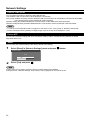
Reset
You can reset the network setting to the factory default of the Display.
1
Select [Reset] in [Network Settings] menu and press
button.
Network Settings
Reset
Yes
2
No
Select [Yes] and press
.
It takes some time to restart network while the network settings are initialized.
During that time, “Network Settings” in the “Setup” menu is grayed out and cannot be set.
22
Connecting with Wired LAN
To use the network function, make the necessary settings in [Network Settings] and be sure to set LAN to enabled
in [Control I/F Select] and [DIGITAL LINK mode]. (See page 20)
Computer operation
Connection can be made with wired LAN. However, confirm to your system administrator on network settings
before changing any settings.
1
Turn on the computer.
2
Make the network setting according to your system administrator.
If the Display settings are the default settings (See page 13), the computer can be used with the following
network settings.
IP address
Subnet mask
Gateway
192.168.10.101
255.255.255.0
192.168.10.1
Connecting with Wireless LAN
Computer operation
1
Make the network setting according to your system administrator.
• If you select [M-DIRECT] for [Wireless LAN] in the [Network Settings] menu, the IP address will
•
automatically be acquired.
If you select default settings of [USER1] - [USER3] for [Wireless LAN] in the [Network Settings] menu (see
page 17), then the computer can be used with the following network settings.
IP address
Subnet mask
Gateway
2
192.168.11.101
255.255.255.0
192.168.11.1
Connect to the wireless network that has the same [SSID] set with the Display.
When you select default settings of [M-DIRECT] for [Wireless LAN] in the [Network Settings] menu, the
SSID is [M-DIRECT + The last 4 digits of the Display ID].
When you select default settings of [USER1] - [USER3] for [Wireless LAN] in the [Network Settings] menu,
the SSID is [Panasonic Display].
• If you use any wireless utility other than Windows [Wireless Network Connection], follow its operation
procedure for connection.
• If you use the access point, configure the Display and each network setting of the computer following the
instruction of the network administrator.
23
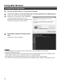
Using Web Browser
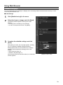
Accessing from the Web browser
1
2
3
Activate the Web browser in the personal computer.
Enter the IP address set by the Display into the URL input field of the Web browser.
Enter your “User name” and “Password”.
The factory default settings are user1 (user
privileges) or admin1 (administrator privileges) for the
user name and panasonic for the password.
4
Click [OK] to display the Display status
page.
TH-50LFB70
“Display status” page is displayed.
• Avoid activating two or more Web browser simultaneously to work out setting or control actions.
• Change the password first of all.
• Administrator privileges enable the use of all functions. User privileges enable the use of only “Display status”,
“Network status”, “Basic control”, “Advanced control”, and “Change password”.
• If the password is incorrectly entered three times in a row, the lock is set for several minutes.
• If you want to control the Display using a Web browser, set [WEB Control] in [Network Settings] menu to [On].
24
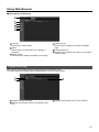
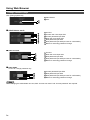
Using Web Browser
■ Description of each item
1
TH-50LFB70
2
3
4
5
6
Page tab
Click these to switch pages.
2 Status
Click this item, and the status of the Display is
displayed.
3 Display control
Click this item to display the Display control page.
1
Detailed set up
Click this item to display the advanced settings
page.
5 Change password
6 Click this item to display the Crestron Connected™
operation page.
4
Display status page
Click [Status], then [Display status] to display the Status information page.
This page displays the Display statuses established for the items shown below.
1
2
1
2
TH-50LFB70
Displays the type of Display.
Displays the firmware version of the Display main
unit.
3
3
Displays the firmware version of the network.
25
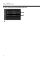
Using Web Browser
Network status page
Click [Status], then [Network status] to display the Status information page.
Displays the current configuration information of the network.
1
2
26
1
Displays the configuration details of wireless LAN.
2
Displays the configuration details of wired LAN.
Using Web Browser
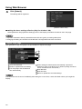
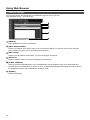
Basic control page
To move from another page, click [Display control], then [Basic control].
1
Miracast(TM)
2
3
4
1
2
Power On/Off control
Use these to select the input signals
3
4
Operation of AV mute
Switches aspect mode
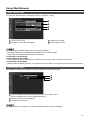
The following points will be different when connected wirelessly.
• Switching to Miracast™ and MEMORY VIEWER input will not be possible.
• Control will not be possible with Crestron Connected™.
TH-50LFB70U, TH-65LFB70U,
TH-50LFB70W, TH-65LFB70W
• When [Wireless Network Standby] is off, operation for turning the power on/off will not be shown.
TH-50LFB70E, TH-65LFB70E
• [Wireless Network Standby] function is not supported, and operation for turning the power on/off will not be shown.
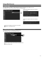
Detail control page
Click [Display control], then [Advanced control] to display the Detail control page.
1
2
3
Enter a command. Use the same command used for the serial control.
(refer to “Operating Instructions, Display Operations”)
2 Response from the unit is displayed.
3 Command is sent and run.
1
After the settings are changed, it may take a while till the display status is displayed.
27
Using Web Browser
Change Password page
Click [Change password].
Administrator
2 User
1
1
2
■ Administrator mode
1
2
3
4
5
6
7
1
2
3
4
5
6
7
Account
Current user name input field
Current password input field
New user name input field
New password input field
New password input field (re-enter for confirmation)
Button for executing password change
■ User account
1
2
3
4
5
Account
New user name input field
3 New password input field
4 New password input field (re-enter for confirmation)
5 Button for executing password change
1
2
■ User mode
A user can change password only.
Current password input field
2 New password input field
3 New password input field (re-enter for confirmation)
4 Button for executing password change
1
1
2
3
4
When changing the administrator account, both “Current user name” and “Current password” are required.
28
Using Web Browser
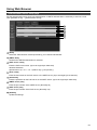
Network config page
You can make detail network settings on Display, when connecting without the administrator authority or when
connecting with Wireless LAN.
■ LAN settings
1
Click [Detailed set up] in the menu.
2
Select the items to change and click [Next].
3
Complete the detailed settings and click
[Next].
The settings window appears, showing the current
settings.
• To change the LAN settings, click [Change].
• To return to the previous window, click [Back].
When [Next] is clicked, the next page appears, enabling
you to complete the detailed settings as desired.
Settings performed here are the same as the settings
performed with the [Network Settings] menu of the
Display.
• Wired LAN (See page 13)
• Wireless LAN (See page 14)
After all required items have been entered, a confirmation
window appears.
(Wireless LAN screen)
29
Using Web Browser
4
Click [Submit].
The settings will be registered.
(Wireless LAN screen)
■ Making the above settings effective (Only for wireless LAN)
Select [Wireless LAN] in [Network Settings] menu of the Display, and select the network set in this page.
• Important video/audio data is protected because AES encryption processing takes place.
• Changing the setting of LAN while connected with LAN might disconnect the connection.
Adjust clock page
Click [Detailed set up], then [Adjust clock] to display the Adjust clock page.
1
2
3
4
5
6
7
Time zone selection
Button to update time zone setting
3 Turn this [ON] to set the date and
time automatically.
1
2
When setting the date and time automatically, input the IP
address or name of the NTP server. (When inputting the server
name, the DNS server must be set.)
5 New date field
6 New time field
7 Button to update time and date settings
4
If the time becomes incorrect immediately after setting the correct time, contact the dealer where you bought the
Display.
30
Using Web Browser
Ping test page
This page makes it possible to check whether the network is connected to the DNS server, etc.
Click [Detailed set up], then [Ping test] to display the Ping test page.
Display which appears when the connection
was successful.
1
2
Display which appears when the connection
failed.
1
2
Enter the IP address of the server to be tested.
Button for conducting the test.
Command port set up page
Set the port number to be used with command control.
Click [Detailed set up] → [Command port set up].
1
2
1
Input the port number to be used with command control
2
Setting update button
31
Using Web Browser
E-mail set up page
You can send image data displayed by the whiteboard function using an E-mail.
Click [Detailed set up] → [E-mail set up].
1
2
3
4
5
6
1
[ENABLE]
Select [Enable] to use the e-mail function.
2
[SMTP SERVER NAME]
Enter the IP address or the server name of the e-mail server (SMTP). To enter the server name, the DNS
server needs to be set up. (Up to 63 single-byte characters)
3
[MAIL FROM]
Enter the e-mail address of the display. (Up to 63 single-byte characters)
4
[SUBJECT]
Enter the subject of the e-mail. (Up to 63 single-byte characters)
5
[E-MAIL ADDRESS]
Enter the recipient email addresses. Up to 64 addressees can be registered using up to 2048 characters.
Separate each e-mail address by a comma. A list of set addresses is displayed through the e-mail function of
the whiteboard function and is available for sending e-mails.
6
[SUBMIT]
Update the settings.
32
Using Web Browser
Authentication server setup page
Set the authentication items when POP authentication or SMTP authentication is necessary to send an e-mail.
Click [Detailed set up] → [Authentication set up].
1
2
3
4
5
6
7
8
1
[Auth]
Select the authentication method specified by your network administrator.
2
[SMTP Auth]
Set when the SMTP authentication is selected.
3
[POP server name]
Enter the POP server name. (Up to 63 single-byte characters)
Allowed characters:
Alphanumerics (A - Z, a - z, 0 - 9) Minus sign (-) and period (.)
4
[User name]
Enter the user name for the POP server or the SMTP server. (Up to 63 single-byte characters)
5
[Password]
Enter the password for the POP server or the SMTP server. (Up to 63 single-byte characters)
6
[SMTP server port]
Enter the port number of the SMTP server. (Normally 25)
7
[POP server port]
Enter the port number of the POP server. (Normally 110)
8
[Submit]
Update the settings.
33
Using Web Browser Control
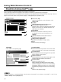
Crestron Connected™ page
You can monitor or control the Display using Crestron Connected™.
When you click [Crestron Connected™], the Crestron Connected™ operation page is displayed.
If Adobe Flash Player is not installed in your computer, or if the browser does not support Flash, this page does not
appear. In this case, return to the previous page by clicking [Back] in the operation page.
Operation page
Panasonic LCD Display
1
1
2
2
3
4
3
5
4
6
7
5
6
7
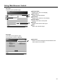
Tools page
Click Tools on the operation page.
1
Panasonic LCD Display
1
2
2
3
3
4
4
5
5
Tools, Info, Help
Switches the pages for tools, information, help
using the tab.
POWER
Switches between on and off of the power.
VOL DOWN, AV MUTE, VOL UP
Sets the volume, AV mute. When the power of the
Display is turned off, VOL DOWN, AV MUTE and
VOL UP are not available.
Input Select
Sets the input selection. When the power of
the Display is turned off, this operation is not
available.
Operation buttons on the menu screen
Operates on the menu screen.
Image quality adjustments
Operate items related to image quality.
Back
Returns to the previous page.
Control system
Sets the information required for the communication
with the controller that is connected to the Display.
User Password
Sets the password for the user rights in the operation
page of Crestron Connected™.
Admin Password
Sets the password for the administrator rights in the
operation page of Crestron Connected™.
Network status
Displays the setting of LAN.
DHCP: Displays the value in the current setting.
IpAddres: Displays the value in the current setting.
SubnetMask: Displays the value in the current setting.
DefaultGateway: Displays the value in the current setting.
Exit
Return to the operation page.
When you monitor or control the Display using Crestron Connected™, set “Crestron Connected™” to “On” in the
“Network Settings” menu. (see page 19)
34
Using Web Browser Control
Info page
Click Info on the operation page.
1
Panasonic LCD Display
4
1
Name1234
5
2
3
2
3
4
6
5
6
Display Name
Displays the name of the Display.
Mac Address
Displays the MAC address.
Resolution
Displays the resolution of the Display.
Power Status
Displays the status of the power.
Source
Displays the selected video input.
Exit
Return the operation page.
Help page
Click Help on the operation page.
The Help Desk screen is displayed.
Panasonic LCD Display
1
1
Help Desk
Sends or receive messages to the administrator who
uses Crestron Connected™.
Name1234
35
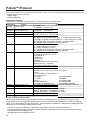
PJLink™ Protocol
The network function of the unit conforms with PJLink™ class 1 and you can operate the following actions from your
computer using PJLink™ protocol.
• Display setup
• Display status query
Supported commands
Commands to control the unit with PJLink™ protocol are shown in the table below.
Command
Control
POWR
Power control
POWR?
Power status query
INPT
INPT?
AVMT
Input switch
Input switch query
Shutter control
AVMT?
Shutter control query
ERST?
Error status query
LAMP?
INST?
Lamp status query
Input switch list query
NAME?
INF1?
INF2?
Display name query
Manufacturer name query
Model name query
INFO?
CLSS?
Other information query
Class information query
Remark
Parameter
0 = Standby 1 = Power “On”
Parameter
0 = Standby 1 = Power “On”
Parameter
See the parameter for command INST?
Parameter
10 = Picture On (picture mute deactivated), 11 = Picture Off (picture on mute)
20 = Audio On (audio mute deactivated), 21 = Audio Off (audio on mute)
30 = Shutter mode Off (picture and audio mute deactivated)
31 = Shutter mode On (picture and audio on mute)
Parameter
11 = Picture Off (picture on mute)
21 = Audio Off (audio on mute)
30 = Shutter mode Off (picture and audio mute deactivated)
31 = Shutter mode On (picture and audio on mute)
Parameter
First byte: Means fan error. 0 or 2.
Second byte: 0
Third byte: 0
Fourth byte: 0
Fifth byte: 0
Sixth byte: Means other error. 0 or 2.
Meaning of the 0 – 2 settings:
0 = Error is not detected, 2 = Error
Not supported
■INST ?Command
%1INST=11 12 13 21 22 31 32 33 34 35 51 52 53
11: PC
12: SLOT INPUT or SLOT INPUT A
13: SLOT INPUT B
21: VIDEO
22: COMPONENT
31: HDMI1
32: HDMI2
33: DVI
34: DIGITAL LINK
35: WHITEBOARD
51: Miracast(TM)
52: Panasonic APPLICATION
53: MEMORY VIEWER
The name set for [Name Change] in [Network Settings] is returned.
Returns “Panasonic”
Returns “50LFB70U” / “65LFB70U” (U model)
Returns “50LFB70E” / “65LFB70E” (E model)
Returns “50LFB70W” / “65LFB70W” (W model)
Returns version number
Returns “1”
PJLink™ security authentication
When using PJLink with security authorization, either of the password set for administrator privileges and the
password set for user privileges with Web browser control can be used as the password for PJLink (See page 24).
When using PJLink without security authorization, set use without the password for administrator privileges and the
password for user privileges of Web browser control.
• PJLink™ is a pending trademark in Japan, the United States, and other countries and regions.
Concerning the specification of PJLink™, see the website of Japan Business Machine and Information System
Industries Association (JBMIA) below:
http://pjlink.jbmia.or.jp/english/index.html
36
Trademarks
• VGA is a trademark of International Business Machines Corporation.
• Microsoft®, Windows®, Windows Vista®, and Internet Explorer ® are the registered trademarks or trademarks of
•
•
•
•
•
•
•
•
Microsoft Corporation in the United States and/or other countries.
Macintosh, Mac, Mac OS, OS X and Safari are the trademarks of Apple Inc. registered in the United States and
other countries.
SVGA, XGA, SXGA and UXGA are registered trademarks of the Video Electronics Standard Association.
Even if no special notation has been made of company or product trademarks, these trademarks have been fully
respected.
PJLink is a pending trademark in Japan, the United States and other countries and regions.
HDMI, the HDMI logo and High-Definition Multimedia Interface are trademarks or registered trademarks of HDMI
Licensing LLC.
RoomView, Crestron RoomView and Fusion RV are registered trademarks of Crestron Electronics, Inc, and
Crestron Connected is the trademark of Crestron Electronics, Inc.
Miracast is the trademark of Wi-Fi Alliance.
Android is the trademark of Google Inc.
iPad, iPhone, iPod touch are trademarks or registered trademarks of Apple Inc. registered in the United States
and other countries.
USA only: Disposal may be regulated in your community due to environmental considerations. For disposal or
recycling information, please visit Panasonic website:
http://www.panasonic.com/environmental
or call 1-888-769-0149.
Customer’s Record
The model number and serial number of this product can be found on its rear cover. You should note this serial
number in the space provided below and retain this book, plus your purchase receipt, as a permanent record of
your purchase to aid in identification in the event of theft or loss, and for Warranty Service purposes.
Model Number
Serial Number
For TH-50LFB70U and TH-65LFB70U
Panasonic System Communications Company of North America
Unit of Panasonic Corporation of North America
Executive Office :
Two Riverfront Plaza, Newark, New Jersey 07102-5490
Panasonic Canada Inc.
5770 Ambler Drive
Mississauga, Ontario
L4W 2T3
Web Site : http://panasonic.net
© Panasonic Corporation 2014
![MC67 with Android OS Regulatory Guide [English] (P/N](http://vs1.manualzilla.com/store/data/006084956_1-8e27f4789c5d6b385775ffdddd01c56d-150x150.png)
![TC55 Regulatory Guide [English] (P/N MN000016A03 Rev. A)](http://vs1.manualzilla.com/store/data/006084957_1-919751c600ce55e2e6481c06e14d0eb9-150x150.png)