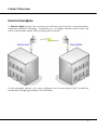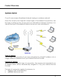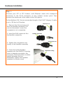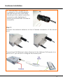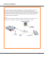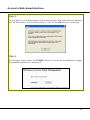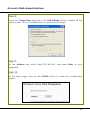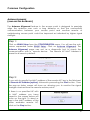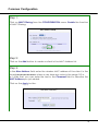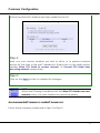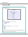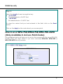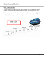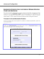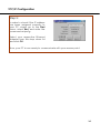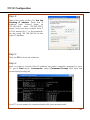
1
NETKROM OUTDOOR AP/BRIDGE MODELS AIR-BR500G/GH AIR-BR500AG User’s Manual May-06 v1.36 CHAPTER 1: PRODUCT OVERVIEW .............................................1 Introduction ..........................................................................................................1 Features and Benefits ..........................................................................................2 When to use which mode ...................................................................................3 Access Point Mode............................................................................................ 3 Access Point Client Mode ................................................................................ 4 Point to Point Mode ........................................................................................... 5 Point to Multiple point Mode ........................................................................... 6 Wireless Routing Client Mode .......................................................................... 7 Gateway Mode.................................................................................................. 8 Wireless Adapter Mode .................................................................................... 9 CHAPTER 2: HARDWARE INSTALLATION...................................10 Warnings .............................................................................................................10 Package contents .............................................................................................11 Setup Requirements...........................................................................................12 Outdoor ap installations....................................................................................13 Mounting ap in the pole or tower................................................................. 17 CHAPTER 3: ACCESS TO WEB-BASED INTERFACE....................18 Access to the Web interface with uConfig......................................................18 Verify the IP address of the Access Point with NpFind ...................................22 Manual access to web-based interface via Internet Explorer .....................23 CHAPTER 4: COMMON CONFIGURATION ..............................28 Management Port Setup ...................................................................................28 Setting up your LAN ......................................................................................... 29 To view the active DHCP leases .................................................................... 32 To reserve specific IP addresses for predetermined DHCP clients.......... 33 WLAN Setup ........................................................................................................36 To configure the Basic setup of the wireless mode ................................... 38 To configure the Security setup of the wireless mode............................... 52 To configure the Advanced setup of the wireless mode ......................... 52 Statistics.............................................................................................................. 55 WAN Setup..........................................................................................................62 (only supported by Wireless Routing Client and Gateway) ..........................62 SNMP Setup ........................................................................................................70 Table of Contents STP Setup.............................................................................................................71 (Only available in Access Point, Point to Point and Point to Multiple Point modes)................................................................................................................71 MAC Filtering......................................................................................................75 CHAPTER 5: WLAN SECURITY....................................................79 How to set up WEP .............................................................................................80 How to set up WPA-PSK/WPA2-PSK/WPA-PSK-AUTO (Only available in Access Point mode) ..........................................................................................81 How to set up 802.1x/RADIUS (Only available in Access Point mode) ........83 How to set up WPA EAP/WPA2-EAP/WPA-EAP-AUTO (Only Access Point mode supports WPA2-EAP and WPA-EAP-AUTO) ...........................................85 CHAPTER 6: WIRELESS EXTENDED FEATURES ............................88 Access Control – The Wireless Pseudo VLAN (Only in Access Point mode) .............................................................................................................................88 Wireless Pseudo VLAN Per Node ................................................................... 89 Wireless Pseudo VLAN Per Group.................................................................. 92 Wireless Setup - The Wireless Distributed System (WDS) (Only in Access Point mode) ...................................................................................................... 96 Long Distance Parameters ........................................................................... 102 CHAPTER 7: ADVANCED CONFIGURATION ..........................105 Routing (only supported by Wireless Routing Client and Gateway) ..........105 To configure Static Routing of The Access Point ...................................... 106 NAT (only supported by Wireless Routing Client and Gateway) ................107 To configure Virtual Servers based on De-Militarized Zone (DMZ) Host 108 To configure Virtual Servers based on Port Forwarding .......................... 110 To configure Virtual Servers based on IP Forwarding .............................. 112 Bandwidth Control (only supported by Wireless Routing Client and Gateway) .........................................................................................................114 To enable or disable Bandwidth Control................................................... 114 To configure WAN Bandwidth Control Setting ......................................... 115 To configure LAN Bandwidth Control Setting ........................................... 116 Remote Management (only supported by Wireless Routing Client and Gateway) .........................................................................................................118 To set up Remote Management................................................................. 118 Parallel Broadband (only supported by Gateway)......................................119 To enable Parallel Broadband on the Access Point................................ 120 iii Table of Contents Email Notification.............................................................................................121 Static Address Translation (only supported by Wireless Routing Client and Gateway) .........................................................................................................123 DNS Redirection (only supported by Wireless Routing Client and Gateway) ...........................................................................................................................125 To enable/disable DNS Redirection............................................................ 127 Dynamic DNS Setup.........................................................................................127 To enable/disable Dynamic DNS Setup..................................................... 128 To manage Dynamic DNS List (DDNS)........................................................ 128 CHAPTER 8: SECURITY CONFIGURATION...............................134 Packet Filtering ................................................................................................134 To configure Packet Filtering........................................................................ 134 URL Filtering.......................................................................................................138 To configure URL Filtering .............................................................................. 138 Firewall Configuration .....................................................................................139 To configure SPI Firewall................................................................................ 139 Firewall Logs .....................................................................................................143 To view Firewall Logs...................................................................................... 143 CHAPTER 9: SYSTEM UTILITIES .................................................144 Using the SYSTEM TOOLS Menu.......................................................................144 Ping Utility......................................................................................................... 144 System Identity................................................................................................ 145 Set System’s Clock ......................................................................................... 146 Firmware Upgrade ......................................................................................... 147 Backup or Reset Settings .............................................................................. 149 Reboot System................................................................................................ 152 Change Password.......................................................................................... 153 Logout .............................................................................................................. 154 Using the HELP menu .......................................................................................155 About System.................................................................................................. 155 APPENDIX I: FIRMWARE RECOVERY.......................................156 APPENDIX II: TCP/IP CONFIGURATION..................................158 For Windows 95/98/98SE/ME/NT .................................................................. 158 iv Table of Contents For Windows XP/2000..................................................................................... 161 APPENDIX III: PANEL VIEWS & DESCRIPTIONS .......................163 APPENDIX IV: TECHNICAL SPECIFICATIONS .........................165 v Chapter 1: Product Overview INTRODUCTION The AIRNET 54Mb Outdoor AP/Bridge series is a high-performance Access Point and Bridge designed for enterprises and outdoor users. It is compatible with IEEE 802.11a/b/g and supports high-speed data transmission up to 54Mb. Housed in a waterproof casing, AIRNET 54Mb Outdoor AP/Bridge series is designed to withstand any extreme climatic conditions, making it the ideal solution for outdoor applications. The AIRNET 54Mb Outdoor AP/Bridge series has the ability to operate in 7 different modes and can be used in a wide variety of wireless applications like Point-to-Point, Point-to-Multipoint, Wireless ISP, Hot Spot and Mesh Network applications. The integrated WDS (Wireless Distribution System) feature creates a virtually larger wireless network infrastructure by linking up other access points. Perfect for applications requiring high bandwidth at a fraction of the cost of T1/E1 leased-line, with the additional advantage of zero monthly recurring cost from the service carrier. Typical usages include bridging satellite offices, corporate LANs, school campus, as well as wireless Internet services, at distances up to 25 miles or 40 Km (using 1 watt amplifier). The Airnet 54Mb Outdoor Bridge High Power also represents the perfect solution for bridging networks that are impossible to connect using wired alternatives, including networks separated by difficult terrains, railroads, or bodies of water. The AIRNET 54Mb Outdoor AP/Bridge series is based in Atheros eXtended Range (XR) chipset and provides powerful features such as High Power, higher throughput, Long Range Parameter Settings, high security 64/128/152 WEP and WPA2, DHCP Server, Spanning Tree Protocol, Web-based Configuration and QOS feature which allows media files to be delivered over the network more efficiently. Designed for outdoor use, the AIRNET 54Mb Outdoor AP/Bridge series is able to draw power through Cat-5 Ethernet cable from our DC injector. This ensures that power is available wherever you need it, without the need of expensive electrical work often associated with outdoor installations. 1 Product Overview FEATURES AND BENEFITS • • • • • • • • • • • • • Outdoor and Waterproof Design Full IEEE 802.11a/b/g compatibility allows inter-operation among multiple vendors. High speed data transfer rate up to 54Mbps WDS - Wireless Distribution System Long-Range Parameter Settings Power over Ethernet - PoE Supports 64/128/152 WEP, WPA and WPA2 SNMP, Web base Management System and Windows-based utility Supports Atheros extended Range (XR) technology Spanning Tree Protocol DHCP Server Bandwidth control SPI Firewall and packet/URL filtering 2 Product Overview WHEN TO USE WHICH MODE The access point is versatile in the sense that it may operate in seven different types of modes: Access Point Mode, Client Mode, Point to Point, Point to Multiple Point, Wireless Routing Client , Gateway and Wireless Adapter. This section presents a brief outline of the different network applications that can be accommodated through the different modes of the access point. ACCESS POINT MODE This is the default mode of your access point. The Access Point mode enables you to bridge wireless clients to access the wired network infrastructure and to communicate with each other. In the example above, the wireless users will be able to access the file server connected to the switch through the access point in Access Point mode. 3 Product Overview ACCESS POINT CLIENT MODE In Access Point Client mode, the access point acts as a wireless client that can operate wirelessly with another access point to perform bridging between two Fast Ethernet networks. The Access Point client cannot communicate directly with any other wireless device. In the example above, the workgroup PCs will be able to access the PCs connected to the access point in Access Point Client mode. 4 Product Overview POINT TO POINT MODE In Point to Point mode, the access point allows point-to-point communication between different buildings. It enables you to bridge wireless clients that are miles or kilometers apart while unifying the networks. In the example above, you may configure two access points (AP) to perform transparent bridging between two buildings 5 Product Overview POINT TO MULTIPLE POINT MODE In Point to Multiple Point mode, this mode is similar to that of the Point to Point mode. But the access point located at one facility is able to connect to up to 8 access points (AP) installed in any direction from that facility. The above illustration describes how this mode operates. 6 Product Overview WIRELESS ROUTING CLIENT MODE An application of this mode would be for the Ethernet port of the Wireless Routing Client to be used for connection with other devices on the network while access to the Internet would be achieved through wireless communication with wireless ISP. The above illustration describes how this mode operates. 7 Product Overview GATEWAY MODE Or put it more simply, Broadband Internet sharing in a wireless network! Since the access point supports several types of broadband connections, the first step in setting up the access point as a Broadband Internet Gateway is to identify the type of broadband Internet access you are subscribed to. Static IP address Use this type of connection if you have subscribed to a fixed IP address or to a range of fixed IP addresses from your Internet Service Provider. Dynamic IP address When powered using this type of connection, the access point requests for an IP address which will be automatically assigned to it by your Internet Service Provider. This type of connection applies for instance, to: • Singapore Cable Vision subscribers • @HOME Cable Service users 8 Product Overview PPP over Ethernet (PPPoE) Select this type of connection if you are using ADSL services in a country utilising standard PPP over Ethernet for authentication. For instance: If you are in Germany which uses T-1 connection or If you are using SingNet Broadband or Pacific Internet Broadband in Singapore. PPTP Select this type of connection if you are using ADSL services in a country utilising PPTP connection and authentication. WIRELESS ADAPTER MODE Similarly to the Access Point Client mode, the access point used in this mode, is able to communicate wirelessly with another access point to perform transparent bridging between two networks. However here, the Wireless Adapter connects a single wired workstation only. No client software or drivers are required while using this mode. 9 Chapter 2: Hardware Installation WARNINGS • Do not work on the system or connect or disconnect cables during periods of lightning activity. • Do not locate the antenna near overhead power lines or other electric light or power circuits, or where it can come into contact with such circuits. When installing the antenna, take extreme care not to come into contact with such circuits, as they may cause serious injury or death. • Only trained and qualified personnel should be allowed to install, replace, or service this equipment. • To meet regulatory restrictions, the radio and the external antenna must be professionally installed. The network administrator or other IT professional responsible for installing and configuring the unit is a suitable professional installer. Following installation, access to the unit should be password protected by the network administrator to maintain regulatory compliance. •The outdoor access point and PoE injector can be damaged by incorrect power application. Read and carefully follow the installation instructions before connecting the system to its power source. 10 Hardware Installation PACKAGE CONTENTS Take a moment to ensure you have all of the following parts in your Outdoor Waterproof Unit installation kit before you begin installing the product. If any parts are missing, please contact your local vendor or contact us at 3054182232. 1 3 5 4 2 6 KIT CONTAINS 1. Airnet Outdoor Access Point 2. Mounting bracket (include: 2 stainless steel U-Bolt, 2 Brackets and 4 screw nuts 3. PoE Injector 4. 100-240v Power supply 5. RJ45 Waterproof Connector System 6. CD ROM 11 Hardware Installation SETUP REQUIREMENTS Before starting, please verify that the following is available: • CAT5/5e or FTP Outdoor Ethernet cable (from the Outdoor AP to PoE Injector) • At least one computer is installed with a Web browser and a wired or wireless network interface adapter • TCP/IP protocol is installed and IP address parameters are properly configured on all your network’s nodes Important! • Configure and verify the outdoor access point operations first before you mount the unit in a remote location. • You may need to install a lightning arrestor to protect your outdoor Access Point from the lightning. • For choosing the best location for your outdoor access point choose an elevated location where trees, buildings and large steel structures will not obstruct the antenna signals and which offers maximum line-of-sight propagation with the users. • Select an appropriate antenna to improve range and/or coverage and the access point also lets you fine-tune parameters such as the transmit power to achieve the best results. 12 Hardware Installation OUTDOOR AP INSTALLATIONS The diagram below shows the overall setup of Outdoor Access Point. 13 Hardware Installation Step 1: Connect your UTP or FTP Outdoor cat.5 Ethernet cable with waterproof connector to the RJ-45 connector on the outdoor access point. Then connect the other end of the cable to the PoE injector. For the Netkrom PoE, the recommended length of the RJ45 Category 5 cable is up to 150 feet or 50 meters. enclosure nut 1.- Remove the thin enclosure nut from the feedthru assembly. This can be discarded. Loosen the compression nut completely 2.- Insert the RJ45 connector thru the feedthru assembly 3.- Tighten the compression nut loosely to the feedthru assembly 4.- Screw the entire feedthru assembly into the RJ45-ECS housing which is already mounted in the enclosure. There should be a rubber gasket between the two assemblies. Tighten the feedthru assembly to create a seal. feedthru assembly compression nut RJ45-ECS housing 14 Hardware Installation 5.- The final step is to tighten the compression nut until the gaskets are tight around the Cat5 cable. Always push the cable toward the connector while tightening to ensure good strain relief of cable to connector. Step 2: Connect the external antenna to the N Female connector of the access point. Connect the RJ45 Ethernet cable attached to the Netkrom PoE Injector to a switch or PC you will use to configure the access point. 15 Hardware Installation Connect the power adapter supplied in the Netkrom PoE kit to the main electrical supply and the power plug into the socket of the injector. Now, turn on your power supply. Notice that the POWER LED has lighted up. This indicates that the access point is receiving power through the Netkrom PoE Injector and that connection between your access point and your network has been established. Note: Please use the power adapter provided in the package. Using a power adapter with a different voltage rating will damage this product. 16 Hardware Installation MOUNTING AP IN THE POLE OR TOWER Outdoor Access Point device can be mounted on the pole or tower as shown in following: 1.-Mount the bracket to the pole with the U-bolts. 2.- Attach the radio to the bracket which was mounted on the pole with the supplied nuts and U-bolts. 3.- Tighten the U-bolts and nuts with hand tools. 17 Chapter 3: Access to Web-based Interface There are two methods to access to the web-based Interface of your access point: • Through our Utility – uConfig You can access to the web-based interface directly without the need to assign a different IP address to your PC. • By entering the IP address of Access point in the address bar of Internet Explorer You need to assign an IP address to your PC, such as 192.168.168.x, where x can take any value from 2 to 254, so that it is in the same subnet as Access point. ACCESS TO THE WEB INTERFACE WITH UCONFIG The powerful uConfig utility has been designed to give you direct access to the Web interface. Step 1: Insert the Product CD into your CD-ROM drive. The CD will run automatically. Step 2: From the Utilities section, select to install the uConfig utility to your hard disk. 18 Access to Web-based Interface Step 3: When the utility has been installed, double-click on the uConfig icon. The following screen will appear, click on the Yes button to proceed. Step 4: Select Wireless-AG Access Point in the Products List section and click on the Open Web button. To retrieve and display the latest device(s) in the list, click on the Refresh button. 19 Access to Web-based Interface Step 5: Do not exit the uConfig program while accessing to the web-based interface. This will disconnect you from the device. Click on the OK button to proceed. Step 6: At the login page, press the LOGIN! button to enter the configuration page. The default password is “password”. 20 Access to Web-based Interface Step 7: You will then reach the home page of your access point’s web-based interface. 21 Access to Web-based Interface VERIFY THE IP ADDRESS OF THE ACCESS POINT WITH NPFIND Another utility program NpFind, intended to help you verify the IP address of your product. Follow the next steps to check the IP address of your access point. Step 1: Insert the Product CD into the CD-ROM drive. It will automatically run. Step 2: Click on Utilities and select NpFind program to run it. The screen will then display the IP address of the device detected. 22 Access to Web-based Interface MANUAL ACCESS TO WEB-BASED INTERFACE VIA INTERNET EXPLORER For this method, you need to assign an IP address to your PC so that it belongs to the same subnet as your access point. In this example, we are using Windows XP for illustration. For Windows 98/98SE/2000/NT/ME, kindly refer to Appendix II “TCP/IP Configuration”. Step 1: Go to your desktop, right-click on My Network Places icon and select Properties. Step 2: Go to your network adapter icon, right click and select Properties. 23 Access to Web-based Interface Step 3: Highlight Internet Protocol (TCP/IP) and click on the Properties button. Step 4: Select the radio button for Use the following IP address. Enter the IP Address and Subnet Mask as 192.168.168.x and 255.255.255.0, where x can be any number from 2 to 254, except 1. In this example, we are using 192.168.168.160 as the static IP Address. 24 Access to Web-based Interface Step 5: Click on the OK button to close all windows. Step 6: Next, in order to check if the IP address has been correctly assigned to your PC, go to Start menu, Accessories, select Command Prompt and type the command ipconfig/all. Your PC is now ready to configure your access point. Step 7: Launch your Web browser. Under the Tools tab, select Internet Options. 25 Access to Web-based Interface Step 8: Open the Connections tab and in the LAN Settings section, disable all the option boxes. Click on the OK button to update the changes. Step 9: At the Address bar, enter http://192.168.168.1 and press Enter on your keyboard. Step 10: At the login page, click on the LOGIN! button to enter the configuration pages. 26 Access to Web-based Interface You will then reach the home page of your access point’s Web interface. 27 Common Configuration Chapter 4: Common Configuration This chapter illustrates the following features, which are available in ALL the operating modes of your access point, unless stated otherwise. • Management Port • WLAN Basic Setup • WLAN Security • STP Setup • SNMP • MAC Filtering • Antenna Alignment MANAGEMENT PORT SETUP This section shows you how to customize the parameters of your access point to suit the needs of your network. It also explains how to make use of the built-in DHCP server of your access point. 28 Common Configuration SETTING UP YOUR LAN You can opt to adjust the default values of your access point and customize them to your network settings. Step 1: Click on Management Port from the CONFIGURATION menu. In the Management Port Setup page, refer to the table below to replace the default settings of Access point with appropriate values to suit the needs of your network. Step 2: Click on the Apply button to save your new parameters. This table describes the parameters that can be modified in the Management Port Setup page. 29 Common Configuration Parameters IP Address Description When the DHCP server of the access point is enabled (unless you set a different DHCP Gateway IP Address), this LAN IP Address would be allocated as the Default Gateway of the DHCP client. The IP address of your Access point is set by default to 192.168.168.1. Network Mask The Network Mask serves to identify the subnet in which your Access point resides. The default network mask is 255.255.255.0. Management Gateway IP (Optional) As a bridge Access Point, the access point does not usually communicate with devices on other IP subnets. However, the Management Gateway here acts as the equivalent of the Default Gateway of a PC, to allow the access point to communicate with devices on different subnets. For instance, if you want to access the access point from the Internet or from a router on the LAN, you can set the IP address of the access point as the Management Gateway IP. The Management Gateway IP address of your access point is set to nil by default. The next two fields (DHCP Start IP Address and DHCP End IP Address) allow you to define the range of IP addresses from which the DHCP Server can assign an IP address to the LAN. DHCP Start IP This is the first IP address that the DHCP server will assign. The Address value that you input here should belong to the same subnet as your access point. For example, if the IP address and network mask of your access point are 192.168.168.1 and 255.255.255.0 respectively, the DHCP Start IP Address should be 192.168.168.X, where X can take any value from 2 to 254. It is pre-set to 192.168.168.100. DHCP Address End IP This is the last IP address that the DHCP server can assign. It should also belong to the same subnet as your access point. For instance, if the IP address and network mask of your access point are 192.168.168.1 and 255.255.255.0 respectively, the DHCP End IP Address should be 192.168.168.X, where X can take any value from 2 to 254. It is pre-set as 192.168.168.254. Parameters DHCP Gateway IP Address Description Though usually, the DHCP server also acts as the Default Gateway of the DHCP client, the access point gives you the option to define a different DHCP Gateway IP Address, which will be allocated as the Default Gateway of the DHCP client. The 30 Common Configuration DHCP client will thus receive its dynamic IP address from the access point but will access to the Internet or to the other LAN through the Default Gateway defined by the DHCP Gateway IP Address. For instance, if the access point is used in Access Point Client mode and connects to an Internet gateway, X, a PC wired to the access point will be unable to obtain a dynamic IP address directly from X. But if you can enable the DHCP server of the access point and set the IP address of X as the DHCP Gateway IP Address, the PC will then obtain its IP address from the access point and access the Internet through X. Always use DNS servers Primary Address these DNS IP Enable this checkbox if you want the access point to only use the DNS server(s) you have specified below. The IP address of the DNS server is usually provided by your ISP. Secondary DNS IP Address This optional field is reserved for the IP address of a secondary DNS server. DHCP Server If you disable the DHCP server, you will need to manually configure the TCP/IP parameters of each computer in your network. 31 Common Configuration TO VIEW THE ACTIVE DHCP LEASES The following will guide you to a page display of the active IP address leases that have been allocated by the built-in DHCP server of Access point. Step 1: Click on Management Port from the CONFIGURATION menu. Step 2: Go to the Advanced DHCP Server Options section, click on the Show Active DHCP leases button. The DHCP Active Leases table displays: • The Host Name of the DHCP client • The IP Address that has been allocated to the DHCP client • Its Hardware (MAC) Address • The date and time at which the IP address leased expires NOTE Invalid date and time displayed in the Lease Expired Time column indicates that the clock of your access point has not been properly set. Please refer to the SYSTEM TOOLS section for more details on how to set the system clock. 32 Common Configuration TO RESERVE SPECIFIC IP ADDRESSES FOR PREDETERMINED DHCP CLIENTS Making an IP address reservation lets you inform the DHCP server to exclude that specific address from the pool of free IP addresses it draws on for dynamic IP address allocation. For instance, if you set up a publicly accessible FTP/HTTP server within your private LAN, while that server would require a fixed IP address, you would still want the DHCP server to dynamically allocate IP addresses to the rest of the PCs on the LAN. The following shows you how to reserve a particular IP address. Step 1: From the Advanced DHCP Server Options section, click on the DHCP Server Reservations button. Step 2: Click on Add button. Step 3: Fill in: The host portion of the IP Address to reserve. The Hardware Address, in pairs of two hex values Press the Apply button to make your new entry effective. 33 Common Configuration The DHCP Server Reservations page will then be refreshed to illustrate the currently reserved IP addresses. DELETE DHCP SERVER RESERVATION If you do not need the DHCP server to reserve an IP address anymore, you can delete the DHCP Server Reservation. Step 1: Click on the reserved IP address that you wish to delete, e.g. 192.168.168.20. Step 2: Click on the Delete button. 34 Common Configuration The DHCP Server Reservations table will then be refreshed to reflect your changes. 35 Common Configuration WLAN SETUP This section shows how to perform the following functions: Basic: This function performs a basic setup of the wireless modes of operation: Access Point mode, Access Point Client mode and other operating modes. Security: This function performs data encryption and protection for the access point. Kindly refer to Chapter 5 on WLAN Security for details. Advanced: This function furthers the basic configuration of the access point by setting the system’s additional parameters: Wireless Pseudo VLAN, WDS Configuration and Long Distance Parameters. Kindly refer to Chapter 6 on Wireless Extended Features for details. Statistics: This function uses the Scan Feature to monitor and interpret the statistics data collected. MAC Filtering (only applicable to Access Point mode): MAC Filtering acts as a security measure by restricting the users accessing to the network through their MAC address. Antenna Alignment: It is a tool for aligning outdoor antenna between 2 access points over long distances. The signal level can be checked from the web page and also from the DIAG LED indicator. The DIAG LED indicates the signal strength as described below: Signal Strength Above 20dBm Status of DIAG LED Stays turned ON 36 Common Configuration Between 19 and 17 dBm Flashes 6 times Between 17 and 14 dBm Flashes 3 times Between 13 and 10 dBm Flashes ONCE Below 10dBm Turns OFF NOTE The signal strength of below 10dBm is not recommended for outdoor long distance connection. 37 Common Configuration TO CONFIGURE THE BASIC SETUP OF THE WIRELESS MODE The following will guide you to configure the basic setup of the wireless mode you have selected. Step 1: Click on WLAN Setup from the CONFIGURATION menu. You will see the submenus expanded under WLAN Setup. Click on Basic. The default operating mode of the access point is the Access Point mode. AIR-BR500G/GH AIR-BR500AG 38 Common Configuration Step 2: (Optional: Change Current mode) If you wish to change the current mode of your access point, click on Change, select your Operation Mode and click on the Apply button to access the setup page of your selected mode. Then you are prompted to reboot the access point so as to effect the mode setting. Step 3: Enter the parameters in their respective fields, click on the Apply button and reboot your device to let your changes take effect. Note that the WLAN Basic Setup page for the Client mode is different from that of the Access Point mode. AIR-BR500G/GH AIR-BR500AG If you wish to set the access point in the Point to Point mode, click on Change to select Point to Point, and then you will see the page below. 39 Common Configuration AIR-BR500G/GH AIR-BR500AG If you wish to set the access point in the Point to Multiple Point mode, click on Change to select Point to Multiple Point, and then you will see the page below. AIR-BR500G/GH AIR-BR500AG To create a new peer MAC, click on the Peer MAC List button. The page will appear. ( Please take note that PtMP stands for Point to Multiple Point ). Click on Add, and then you are prompted to key in Hardware Address and Comment. 40 Common Configuration This table describes the parameters that can be modified in the WLAN Basic Setup page. Parameters The Current Mode Description The default operating mode of the access point is the Access Point mode. The access point can operate in 7 modes: • Access Point • Client • Point to Point • Point to Multiple Point • Wireless Routing Client • Gateway • Wireless Adapter You can toggle the mode by clicking on the Change button. ESSID Enter a preferred name for the wireless network. Your wireless clients must be configured with the same ESSID. This case-sensitive entry can consist of a maximum of 32 characters. Site Survey A list of wireless devices that are detected by your access point in the WLAN. Information such as MAC address, channel, SSID, algorithm and signal strength can 41 Common Configuration be found in the listing. This feature is supported by the Access Point Client and Wireless Routing Client modes. Wireless Profile A selection of network environment types in which to operate the access point: • 802.11a only (only for AIR-BR500AG) This mode supports wireless A clients with data rates of up to 54 Mbps in the frequency range of 5.8 Ghz. • 802.11b only (Available for AIR-BR500G/GH and AG) This mode supports wireless B clients with data rates of up to 11Mbps in the frequency range of 2.4GHz. 802.11b/g mixed (Available for AIR-BR500G/GH and AG) This mode supports both wireless B and G clients. • • 802.11g only (Available for AIR-BR500G/GH and AG) This mode supports wireless-G clients that offer transmission rates of up to 54Mbps in the 2.4GHz frequency band. Peer Mac ( Only in Point-to-Point mode ) This mode can support more than one access point. This feature allows you to create a new peer MAC for another access point so that the router operating in the access point mode can connect to another access point. Peer MACs (Only in Point-toMultiple Point mode) This mode can support up to 15 access points. This feature allows you to create up to 15 peer MAC addresses so that the router can connect to this number of the access points. Country Choose the Country where you are located. Channel This option allows you to select a frequency channel for the wireless communication. This parameter is only available in the Access Point, Point to Point and Point to Multiple Point modes. 42 Common Configuration Tx Rate Allow you to choose the rate of data transmission from 1Mbps to Fully Auto (AIR-BR500G/GH) and from 6Mbps to Fully Auto (AIR-BR500AG) Closed System The access point will not broadcast its WLAN name (ESSID) when Closed system is enabled. By default Closed system is disabled. Channel Survey A list of channels that are detected by your access point in the WLAN. Information such as frequency, channel, MyQuality, NeighQuality, APCount and Recommendation can be found in the listing. The Access Point and Gateway modes support this feature. 43 Common Configuration SCAN FOR SITE SURVEY (ONLY FOR CLIENT MODE AND WIRELESS ROUTING CLIENT MODE ) Step 1: In the Mode Setup page, click on the Site Survey button. The Site Survey provides a list of the MAC addresses (BSSID) and SSID of neighbouring access points detected, the Chan (channels), Auth (Authentication), Alg (Algorithm) used, and the strength of the Signal received. 44 Common Configuration Site Survey on the 2.4 Ghz frequency band Step 2: To connect the access point client to one of the access points detected: Select the radio button corresponding to the access point you want to connect to. Step 3: Click on the Apply button to effect the change and return to the setup page. Step 4: Click on the Refresh button to update this screen. This table describes the read-only parameters of neighbouring access points that can be viewed from the Site Survey page. 45 Common Configuration Parameters Bssid Description In an infrastructure wireless network, the BSSID refers to the wireless MAC address of the access point. SSID Refers to the network name that uniquely identifies the network to which the access point is connected. Chan Refers to the channel being used for transmission. Auth Refers to the types of authentication, such as WPA, WPAPSK, etc being used by the access point. Alg Refers to the types of algorithm, such as WEP, TKIP, etc being used by the access point. Signal Describes the percentage. strength of the signal received in NOTE The purpose of using Site Survey is to scan and display all access points based on the current security setting of your access point. For instance, the following information supplied by the Site Survey according to the security setting is explained: • If the security mode is set to None or WEP, the scan will show all available access points that have no security or WEP security • If the security mode is set to WPA-PSK, the scan will show all available access points having all types of security from no security, WEP security to WPA-PSK security. 46 Common Configuration SHOW LINK INFORMATION (ONLY FOR CLIENT MODE AND WIRELESS ROUTING CLIENT MODE) Step 1: To view the connection status when the access point client is linked to another access point, click on the Show Link Information button. The Link Information table illustrates the following data: This table describes the parameters that can be viewed from the Link Information page. Parameters Description State Refers to the MAC address of the BSS (AP to which the access point client is connected). Current Channel The channel that is being presently used for transmission. Tx Rate Signal Strength The rate of data transmission in Mbps. Given in percentage, showing the intensity of the signal received. 47 Common Configuration SCAN FOR CHANNEL SURVEY (AVAILABLE FOR ACCESS POINT MODE AND GATEWAY MODE ) Channel Survey provides a list of all channels that are supported by the access point. This feature will show relative interference of all channels and recommend the least congested channel. When the users want to scan for and find the best channel, they can use Channel Survery. Step 1: In the Mode Setup page, click on the Channel Survey button. The Channel Survey provides a list of the Freq (frequency) and Channel of the access point detected, the APCount, MyQuality (your access point’s interference from your access point’s channel signal) recieved and NeighQuality (interference from the neighbouring access points’ channel signals) received. 48 Common Configuration Channel Survey on the 2.4 Ghz frequency band Please take note that the MYQuality and NeighQuality are RSSI values. If the value is higher which means that you receive the stronger signal strength from several APs, it indicates that the higher interference from these APS will occur as well. The value of zero indicates no interference. Step 2: To connect the access point client to one of the channels detected, select the radio button corresponding to the channel you want to connect to. Step 3: Click on the Apply button to effect the change and return to the setup page. Step 4: Click on the Refresh button to update this screen. This table describes the read-only parameters of all channels that can be viewed from the Channel Survey page. 49 Common Configuration Parameters Freq Description Refers to the frequency of the channel at which your access point is operating. Channel Refers to the channel of the access point being used for transmission depending on its origin of country. MyQuality Refers to the interference having a RSSI value caused by the current channel at which your access point is operating. APCount Refers to the total number of access points operating at the current channel. NeighQuality Refers to the interference having a RSSI value caused by the neighbouring channels. Recommendation Means that you can recommend the best (preferably least congested) channel. 50 Common Configuration ANTENNA ALIGNMENT (AVAILABLE FOR ALL MODES ) The Antenna Alignment feature in the access point is designed to precisely align the antenna over such a long distance so that the connectivity communication between your access point and another remote or neighbouring access point could be improved as indicated by higher signal strength. Step 1: Click on WLAN Setup from the CONFIGURATION menu. You will see the submenus expanded under WLAN Setup. Click on Antenna Alignment. The Antenna Alignment page can act as a diagnostic tool to check the communication with a remote device. The remote AP MAC Address is preset to all zeros by default. Step 2: If you wish to specify the MAC address of the remote AP, key in the field next to Remote AP Address (option), followed by executing the Start button. Then the pop-up status screen will show up, allowing you to monitor the signal strength received from the remote access points. If there is no specified AP with its MAC address you have keyed in, the screen below will show on the right. To abort or key in the MAC address of the other available remote AP, click on the Stop button. 51 Common Configuration NOTE If no MAC address is entered, the Antenna Alignment tool will make use of the SSID to align the antenna. Please make sure that the correct SSID is entered. If more than one access point (AP) share the same SSID, the Antenna Alignment tool will show the strongest signal AP. TO CONFIGURE THE SECURITY SETUP OF THE WIRELESS MODE Kindly refer to Chapter 5 on WLAN Security for details on setting the different security modes of the access point. TO CONFIGURE THE ADVANCED SETUP OF THE WIRELESS MODE The following will guide you to configure the advanced setup of the wireless mode you have selected. Step 1: Click on WLAN Setup from the CONFIGURATION menu to expand into the four sub-menus. From here, click on Advanced. Step 2: In the WLAN Advanced Setup page, enter the parameters. Step 3: Click on the Apply button to update the changes. 52 Common Configuration This table describes the parameters that can be modified in the WLAN Advanced Setup page. Parameters Description Beacon Interval The Beacon Interval is the amount of time between (Only in Access beacon transmissions. A beacon is a guidance signal Point mode) sent by the access point to announce its presence to other devices in the network. Before a client enters the power-save mode, it needs the beacon interval to know when to wake up to receive the beacon (and learn whether there are buffered frames at the access point). Data Beacon Rate (DTIM) (Only in Access Point mode) The Data Beacon Rate (DTIM) determines how often the beacon contains a delivery traffic indication message (DTIM). The DTIM identifies which clients (in power-save mode) have data frames waiting for them in the access point’s buffer. If the beacon period is set at 100 (default value), and the data beacon rate is set at 1 (default value), then the access point sends a beacon containing a DTIM every 100 Kμsecs (1 Kμsec equals 1,024 μsec). RTS/CTS Threshold The RTS/CTS Threshold value determines the minimum size of a packet in bytes that would trigger the RTS/CTS mechanism. 53 Common Configuration Frag Threshold The Frag Threshold value indicates the maximum size that a packet can reach without being fragmented. This value extends from 256 to 2346 bytes, where a value of 0 indicates that all the packets should be transmitted using RTS. Transmit Power The Transmit Power drop-down list lets you pick from a range of transmission power. For details on how to configure Wireless Pseudo VLAN, WDS and Long Distance Parameters, kindly refer to Chapter 6 on Wireless Extended Features. NOTE The values illustrated in the examples are suggested values for their respective parameters. 54 Common Configuration STATISTICS The following shows you the information on the wireless device that is connected to the WLAN. IN ACCESS POINT MODE Step 1: Click on WLAN Setup from the CONFIGURATION menu. You will see the submenus expanded under WLAN Setup. Click on Statistics. Wireless clients that are connected to the WLAN are shown in the WLAN Station List. Step 2: Click on the Refresh button to get the latest information on the availability of wireless clients in the wireless network. Step 3: To check the details on individual wireless client, click on the MAC Address in the WLAN Station List. The following screen will show the statistics of the selected wireless client. 55 Common Configuration 56 Common Configuration IN CLIENT MODE Click on WLAN Setup from the CONFIGURATION menu. You will see the submenus expanded under WLAN Setup. Click on Statistics. In Client mode, you are not allowed to view other wireless clients’ statistics. To view other wireless clients information, you need to change to Access Point mode. 57 Common Configuration IN POINT TO POINT MODE Click on WLAN Setup from the CONFIGURATION menu. You will see the submenus expanded under WLAN Setup. Click on Statistics. In Point to Point mode, you are not allowed to view other wireless clients’ statistics. To view other wireless clients information, you need to change to Access Point mode. 58 Common Configuration IN POINT TO MULTIPLE POINT MODE Click on WLAN Setup from the CONFIGURATION menu. You will see the submenus expanded under WLAN Setup. Click on Statistics. In Point to Multiple Point mode, you are not allowed to view other wireless clients’ statistics. To view other wireless clients information, you need to change to Access Point mode. 59 Common Configuration IN WIRELESS ROUTING CLIENT MODE Click on WLAN Setup from the CONFIGURATION menu. You will see the submenus expanded under WLAN Setup. Click on Statistics. In Wireless Routing Client mode, you are not allowed to view other wireless clients’ statistics. To view other wireless clients information, you need to change to Access Point mode. 60 Common Configuration IN GATEWAY MODE Click on WLAN Setup from the CONFIGURATION menu. You will see the submenus expanded under WLAN Setup. Click on Statistics. In Gateway mode, you are not allowed to view other wireless clients’ statistics. To view other wireless clients information, you need to change to Access Point mode. 61 Common Configuration WAN SETUP (ONLY SUPPORTED BY WIRELESS ROUTING CLIENT AND GATEWAY) A correct WAN Setup allows you to successfully share your Internet connection among the wired and wireless clients of the access point. To do so, you need to identify the type of broadband Internet access you are subscribed to. If you are using : • Cable Internet where your ISP dynamically assigns a WAN IP address to you, refer to WAN Setup - Cable Internet with Dynamic IP Assignment. • Cable Internet where your ISP provides you with a fixed WAN IP address (or a range of fixed IP addresses), refer to WAN Setup - Cable Internet with Static IP Assignment. • ADSL Internet that requires standard PPP over Ethernet (PPPoE) for authentication, refer to WAN Setup - ADSL Internet using PPP over Ethernet (PPPoE). • ADSL Internet that requires standard Point to Point Tunneling Protocol (PPTP) for authentication, refer to WAN Setup – ADSL Internet using Point to Point Tunneling Protocol (PPTP). WAN Setup - Cable Internet with Dynamic IP Assignment The access point is pre-configured to support a WAN type that dynamically obtains an IP address from the ISP. However, you may verify the WAN settings with the following steps: Step 1: Setup. Under CONFIGURATION on the command menu, click on WAN 62 Common Configuration Step 2: On the WAN Dynamic Setup screen that follows, verify that the WAN Type reads Dynamic (DHCP) in red colour. Otherwise, click on the Change button. Step 3: Simply select Dynamic IP Address and hit the Apply button. Please remember to click Reboot System under SYSTEM TOOLS and hit the Reboot button to let the settings take effect. Note: There are exceptional cases where additional configuration is required before an IP address will be allocated by your ISP to the access point. a. Certain ISPs log the MAC address of the first device used to connect to the broadband channel and will not release a WAN IP address unless the MAC address matches the one in their log. Therefore, if yours is not a new Cable Internet subscription (i.e. your PC was formerly connected directly to your cable modem), refer to steps 4 - 5 to clone the “approved” MAC address onto the access point. b. Certain ISPs require authentication through a DHCP Client ID before releasing a public IP address to you. The access point uses the System Name in the System Identity as the DHCP Client ID. Therefore, if this is the case, refer to your ISP for the correct DHCP Client ID to be set and follow steps 6 - 7 to accomplish the setup. 63 Common Configuration Step 4: Steps 4 - 5 are for those who need to clone their Ethernet adapter’s MAC address. In the WAN Setup found under the CONFIGURATION command menu, you will see the Advanced WAN Options. Click MAC Clone to continue. Step 5: Simply click on the Clone button so that your access point clones the ISPrecognized MAC address of your Ethernet adapter. Please remember to click Reboot System under SYSTEM TOOLS and hit the Reboot button to let the settings take effect. Take note: (If required, you may reset the access point’s MAC address to its factory default by clicking Reset on that same page) Step 6: Steps 6 - 7 are for those who need to set up the System Name in System Identity so that your ISP can authenticate it as a valid DHCP Client ID. Click on System Identity under the SYSTEM TOOLS command menu. 64 Common Configuration Step 7: On the following screen, key in the ISP assigned DHCP Client ID as the System Name (You may also like to key in a preferred Systems Contact person and the System Location of the access point). Click the Apply button to complete. Please remember to click Reboot System under SYSTEM TOOLS and hit the Reboot button to let the settings take effect. 65 Common Configuration WAN Setup - Cable Internet with Static IP Assignment If you have an ISP that leases a static WAN IP for your subscription, you will need to configure your access point’s WAN type accordingly. For example, if the ISP provided you with the following setup information, you can set up your WAN as described below: IP Address : 203.120.12.240 Network Mask : 255.255.255.0 Gateway IP Address : 203.120.12.2 Step 1: Under CONFIGURATION on the command menu, click on WAN Setup. Step 2: Access the Select WAN Type page and choose Static IP Address before clicking the Apply button. You will then be brought to the following page requiring your inputs. Step 3: Fill in the information provided by your ISP in the IP Address, Network Mask and Gateway IP Address fields, before clicking the Apply button. Please remember to click System under SYSTEM TOOLS the Reboot button to let the take effect. Reboot and hit settings 66 Common Configuration WAN Setup - ADSL Internet using PPP over Ethernet (PPPoE) If you subscribe to an ADSL service using PPP over Ethernet (PPPoE) authentication, you can set up your access point’s WAN type as follows. For example, you may configure an account whose username is ‘guest’ as described below: Step 1: Under CONFIGURATION on the command menu, click on WAN Setup. Step 2: Access the Select WAN Type page and choose PPP over Ethernet before clicking the Apply button. You will then be brought to the following page requiring your inputs. Step 3: For Username, key in your ISP assigned account name (e.g. guest for this example), followed by your account Password. Step 4: Select Always-On if you want your access point to always maintain a connection with the ISP. Otherwise, you may select On-Demand. The access point will then connect to the ISP automatically when it receives Internet requests from the PCs in your network. 67 Common Configuration The Idle Timeout setting is associated with the On-Demand option, allowing you to specify the value (in seconds) after which the access point will disconnect from the ISP after the last Internet activity. A value of “0” will disable idle timeout. Reconnect Time Factor is associated with the Always-on option and specifies the maximum time the access point will wait before re-attempting to connect with your ISP. Hit the Apply button and Reboot the access point. WAN Setup – ADSL Internet using PPTP If you subscribe to an ADSL service using Point to Point Tunneling Protocol (PPTP) authentication, you can set up your access point’s WAN type from the steps that follow. For example, if the ISP provided you with the following set up information, you can set up your WAN as described below: IP Address : 203.120.12.47 Network Mask : 255.255.255.0 VPN Server : 203.120.12.15 Step 1: Under CONFIGURATION on the command menu, click on WAN Setup. Step 2: Access the Select WAN Type page and choose PPTP before clicking the Apply button. You will then be brought to the following page requiring your inputs. Step 3: Fill in the information provided by your ISP in the IP Address, Network Mask and VPN Server fields, followed by clicking the Apply button. Please remember to click Reboot System under SYSTEM TOOLS and hit the Reboot button to let the settings 68 Common Configuration take effect. The Idle Timeout setting allows you to specify the value (in seconds) after which the access point will disconnect from the ISP after the last Internet activity. A value of “0” will disable idle timeout. 69 Common Configuration SNMP SETUP Simple Network Management Protocol (SNMP) is a set of communication protocols that separates the management architecture from the architecture of the hardware devices. Step 1: Click on SNMP from the CONFIGURATION menu. Step 2: Select Enable from the SNMP State drop-down list. The default Read Password is set to public while the default Read/Write Password is private. Step 3: Click on the Apply button. 70 Common Configuration STP SETUP (ONLY AVAILABLE IN ACCESS POINT, POINT TO POINT AND POINT TO MULTIPLE POINT MODES) Spanning Tree Protocol (STP) is a link management protocol that helps to prevent undesirable loops occurs in the network. For an Ethernet network to function properly, only one active path can exist between two stations. If a loop exists in the network topology, duplication of messages will occur and this might confuse the forwarding algorithm and allow duplicate frames to be forwarded. 71 Common Configuration In short, the main purpose of activating STP is to prevent looping when you have redundant paths in the network. Without activating STP, redundant topology will cause broadcast storming. To establish path redundancy, STP creates a tree that spans all of the devices in an extended network, forcing redundant paths into a standby, or blocked, state, but establishing the redundant links as a backup in case the active link should fail. If STP costs change, or if one network segment in the STP becomes unreachable, the spanning tree algorithm reconfigures the spanning tree topology and re-establishes the connection by activating the standby path. Without spanning tree in place, it is possible that more than one connection may be simultaneously live, which could result in an endless loop of traffic on the LAN. Spanning-Tree Protocol operation is transparent to end stations, which are unaware whether they are connected to a single LAN segment or a switched LAN of multiple segments. The path with the smallest cost will be used and extra redundant paths will be disabled. 72 Common Configuration To explain the effect of STP & Pseudo VLAN on the wireless clients, we will compare 3 separate scenarios. Scenario #1 – (No STP, No Pseudo VLAN) Referring to the illustration below, if the Spanning Tree Protocol (STP) and Pseudo VLAN are not implemented in a network, all clients (Notebook#1, #2, #3 & #4,) can access to one another, resulting in low level of data security. Due to the redundant paths found in this network, broadcast packets will be duplicated and forwarded endlessly resulting in a broadcast storm. Scenario #2 – (With STP, No Pseudo VLAN) When STP is enabled, extra redundant network paths between APs will be disabled, hence preventing multiple active network paths in-between any two APs. 73 Common Configuration If one of the APs is down, the STP algorithm will reactivate one of the redundant paths so that the network connection will not be lost. All wireless users will be able to communicate with each other if they are associated to the APs which are in the same WDS zone. s Scenario #3 – (With STP and Pseudo VLAN) In this example, both STP and Pseudo VLAN Per Node are implemented in this network. When Pseudo VLAN Per Node is activated, the wireless users will be unable to access one another. 74 Common Configuration Step 1: Click on STP Setup from the CONFIGURATION menu Step 2: Select Enable from the STP State radio button and click on the Apply button to update the changes. MAC FILTERING MAC Filtering acts as a security measure by controlling the users accessing to the network through their MAC address. You can either keep a list of MAC address corresponding to users who are allowed to access the network or to keep a list of MAC address corresponding to users who are forbidden from network access. 75 Common Configuration Step 1: Click on MAC Filtering from the CONFIGURATION menu. Enable the function of MAC Filtering. Step 2: Click on the Add button to create a client in the MAC Address List. Step 3: In the Mac Address field, enter the wireless MAC address of the client, in the format xx-xx-xx-xx-xx-xx, where x can take any value in the range 0-9 or a-f. After that, you can enter the text in the Comment field to describe the MAC Address you just added. Click on the Apply button. 76 Common Configuration Notice that the MAC Address has been added to the list. Step 4: Next, you can choose whether you wish to allow or to prevent network access for the users in the MAC address list. Simply click on the radio button besides Allow PCs listed to access network, or Prevent PCs listed from accessing network, respectively. Step 5: Click on the Apply button to update the changes. NOTE When Mac Filtering is enabled with the Allow PCs listed to access network policy, the Mac Address list cannot be empty. ADD ANOTHER MAC ADDRESS TO THE MAC ADDRESS LIST Follow the procedures mentioned in Step 2 to Step 3. 77 Common Configuration EDIT/DELETE A MAC ADDRESS FROM THE MAC ADDRESS LIST Step 1: Click on the MAC address in the table as shown below. Notice that there is a column labeled Activation in the MAC Address List. When a tick is present, this shows that action will be taken (either to allow or prevent network access) for the PC holding the corresponding MAC address. Step 2: From the Edit MAC Address page, Click on the Delete button to remove the MAC address, or Click on the Save button after you have edited the entry. 78 Chapter 5: WLAN Security This section illustrates how to make your WLAN more secure. All the nodes in your network MUST share the same wireless settings to be able to communicate. We will illustrate how to configure each type of security mode individually. To start with, follow the common preliminary steps described below to select the most appropriate security approach for protecting your wireless communications. Step 1: Click on WLAN Setup from the CONFIGURATION menu to select Security. Step 2: Make a selection from the Security Mode drop down menu. The Security Mode is set to NONE by default. Click on the Apply button. 79 WLAN Security HOW TO SET UP WEP The guidelines below will help you to set up your access point for using WEP. At the WEP Setup page, Step 1: Specify the key entry type, by selecting either: • Use Hexadecimal: • Use ASCII Step 2: Select the Transmission Key from the pull down menu: • Key 1 • Key 2 • Key 3 • Key 4 The access point lets you define up to four different transmission keys. It defines a set of shared keys for network security. You must enter at least one WEP key to enable security using a shared key. 80 WLAN Security Step 3: Select the length of each encryption key: • 64- bit WEP 10 hexadecimal or 5 ASCII Text • 128-bit WEP 26 hexadecimal or 13 ASCII Text To clear the values that you had entered in the field, click on the Reset button. Click on the Apply button and reboot your access point. HOW TO SET UP WPA-PSK/WPA2-PSK/WPA-PSK-AUTO (Only available in Access Point mode) The guidelines below will help you to set up the access point for using WPA-PSK. Please follow the steps below if you have activated WPA-PSK, WPA2-PSK or WPA-PSK-AUTO security modes. At the WPA1/2-PSK Setup page, 81 WLAN Security Step 1: Specify the key entry type, by selecting either: • Passphrase (Alphanumeric characters) • Hexadecimal Step 2: Fill in the WPA-PSK (Pre-Shared network Key): If you are using the Passphrase format, your entry can consist of a minimum of 8 alphanumeric characters or a maximum of 63 alphanumeric characters. Otherwise, when using the Hexadecimal format, your entry MUST consist of 64 hexadecimal characters. Step 3: For WPA-PSK Set the Cipher Type to TKIP. WPA replaces WEP with a strong encryption technology called Temporal Key Integrity Protocol (TKIP) with Message Integrity Check (MIC). For WPA2-PSK Set the Cipher Type to AES. Advanced Encryption Standard (AES) is a stronger symmetric 128-bit block data encryption technique. AES is a requirement of WPA2 under the IEEE 802.11i standard. For WPA-PSK-AUTO Set the Cipher Type to Auto to allow the access point to automatically detect the cipher type to use. Step 4: Enter the GTK (Group Transient Key) Updates. This is the length of time after which the access point will automatically generate a new shared key to secure multicast/broadcast traffic among all stations that are communicating with it. By default, the value is 600 seconds. 82 WLAN Security Step 5: Press the Apply button and reboot your system, after which your settings will become effective. HOW TO SET UP 802.1X/RADIUS (ONLY AVAILABLE IN ACCESS POINT MODE) The guidelines below will help you to set up the access point for using 802.1x/RADIUS. At the IEEE 802.1x Setup page, Step 1: Key in the IP address of the Primary RADIUS Server in your WLAN. You can optionally add in the IP address of a Secondary RADIUS Server, if any. The RADIUS authentication server MUST be in the same subnet as the access point. Step 2: By default, the value for Authentication Port number is 1812. You can leave this value as it is. This value must be set to be the same as the one in the RADIUS server. 83 WLAN Security Step 3: By default, the value for Accounting Port number is 1813. You can leave this value as it is. This value must be set to be the same as the one in the RADIUS server. Step 4: Enter the Shared Secret Key in the field provided. Step 5: By default, the Broadcast Key Rotation is set as 600 seconds. You may leave this value as its default setting. Step 6: Select the length of each encryption key: • 64- bit 10 hexadecimal or 5 ASCII Text • 128-bit 26 hexadecimal or 13 ASCII Text Step 7: Press the Apply button and reboot your system, after which your settings will become effective. 84 WLAN Security HOW TO SET UP WPA EAP/WPA2-EAP/WPA-EAP-AUTO (ONLY ACCESS POINT MODE SUPPORTS WPA2-EAP AND WPAEAP-AUTO) The guidelines below will help you to set up the access point for using WPA-EAP. Please follow the steps below if you have selected the WPA or WPA1-EAP, WPA2-EAP or WPA-EAP-AUTO. At the WPA1/2-EAP Setup page, Step 1: Key in the IP address of the Primary RADIUS Server in your WLAN. You can optionally add in the IP address of a Secondary RADIUS Server, if any. The RADIUS authentication server MUST be in the same subnet as the access point. Step 2: By default, the value for Authentication Port number is 1812. You can either leave this value as it is or key in a different Authentication Port but it MUST match the corresponding port of the RADIUS server. 85 WLAN Security Step 3: By default, the value for Accounting Port is 1813. You can leave this value as it is. This value must be set to be the same as the one in the RADIUS server. Step 4: Enter the Shared Secret Key used to validate client-server RADIUS communications. Step 5: Select the length of each encryption key: • 64- bit 10 hexadecimal or 5 ASCII Text • 128-bit 26 hexadecimal or 13 ASCII Text Step 6: For WPA-EAP Set the Cipher Type to TKIP. WPA replaces WEP with a strong encryption technology called Temporal Key Integrity Protocol (TKIP) with Message Integrity Check (MIC). For WPA2-EAP (Only in Access Point mode) Set the Cipher Type to AES. Advanced Encryption Standard (AES) is a symmetric 128-bit block data encryption technique. It is a requirement of WPA2 under the IEEE 802.11i standard. For WPA-EAP-AUTO (Only in Access Point mode) Set the Cipher Type to Auto to allow the access point to automatically detect the cipher type to use. 86 WLAN Security Step 7: Enter the GTK (Group Transient Key) Updates. This is the length of time after which the access point will automatically generate a new shared key to secure multicast/broadcast traffic among all stations that are communicating with it. By default, the value is 600 seconds. Step 8: Press the Apply button and reboot your system, after which your settings will become effective. 87 Wireless Extended Features Chapter 6: Wireless Extended Features This section illustrates how to configure the wireless extended features. To start with, follow the common preliminary steps described below. ACCESS CONTROL – THE WIRELESS PSEUDO VLAN (ONLY IN ACCESS POINT MODE) A VLAN is a group of PCs or other network resources that behave as if they were connected to a single network segment although they may be physically located on different segments of a LAN. Those stations which are assigned to the same VLAN share network resources and bandwidth as if they were connected to the same segment. Conversely, only the stations within the same VLAN can access each other. A Wireless Pseudo VLAN acts by segregating a single wireless LAN into multiple VLANs so that communication is possible only among wireless clients within the same VLAN. When operating in the Access Point mode, Access point allows you to define Wireless Pseudo VLAN Per Node and Wireless Pseudo VLAN Per Group. 88 Wireless Extended Features WIRELESS PSEUDO VLAN PER NODE When implemented, this mode isolates each wireless client into its own pseudo VLAN. Wireless clients can therefore access resources on the wired network but are unable to see each other or access each other’s data. 89 Wireless Extended Features The following steps demonstrate how to set up a Wireless Pseudo VLAN per Node. Step 1: From WLAN Setup under Configuration, click on Advanced, which shows the WLAN Advanced Setup page. Step 2: Go to the Extended Features section, and click on the Wireless Pseudo VLAN button. Step 3: The Wireless Pseudo VLAN function is disabled by default. Click on the Change button to make your selection of the type of Pseudo VLAN to implement. 90 Wireless Extended Features Step 4: Select the Per node radio button and click on the Apply button. The Wireless Pseudo VLAN has configured as Per node. 91 Wireless Extended Features WIRELESS PSEUDO VLAN PER GROUP The access point can configure up to 32 ‘groups’ of wireless clients identified by their MAC address. Whenever a wireless client requests network access, the access point will first verify whether its MAC address is present in any of the Pseudo VLAN groups. If it is, the access point will grant it access to the wired system resources and to all other wireless clients belonging to the same Pseudo VLAN group only. 92 Wireless Extended Features The following steps demonstrate how to set up Wireless Pseudo VLAN Groups. CREATE A CLIENT IN A PSEUDO VLAN GROUP Step 1: From the Select Wireless Pseudo VLAN Type page, select Per group and click on the Apply button. Step 2: Click on the Add button to create a client in the Wireless Pseudo VLAN group. Step 3: Select a group number from the Group drop-down list. 93 Wireless Extended Features Step 4: Fill in the Hardware Address field with the MAC address of the client in the format xx-xx-xx-xx-xx-xx, where x is any value within the range 0-9 or a-f. Step 5: Click on the Add button to update the changes. The Pseudo VLAN group has been added to the list as shown below. NOTE A client can be a member of more than one Pseudo VLAN group. For instance, if a client is a member of wireless Pseudo VLAN groups 01 and 02, it will be able to communicate with the other clients in both groups. 94 Wireless Extended Features ADD ANOTHER CLIENT IN A PSEUDO VLAN GROUP Follow the procedures mentioned in Steps 3-5. You can create up to 32 members per Wireless Pseudo VLAN group. EDIT/DELETE A CLIENT IN A PSEUDO VLAN GROUP Step 1: Click on the MAC address in the table as shown below. Step 2: From the Edit Wireless Pseudo VLAN Entry page, Click on the Delete button to remove the client from the group, or Click on the Save button after you had edited the entry. 95 Wireless Extended Features WIRELESS SETUP - THE (Only in Access Point mode) WIRELESS DISTRIBUTED SYSTEM (WDS) A wireless distribution system links up several access points, creating a wider network in which mobile users can roam while still staying connected to the available network resources. In a WDS, the access point can drive a cell of wired and wireless clients while at the same time, connecting to other access points. This requires the operational frequency channel to be the same within the cell controlled by your access point as well as for its wireless links to the other access points. Star Configuration WDS In a star configuration WDS, links are established between one root Access point and several satellite wireless APs positioned to increase the area covered. Here, the root Wireless AP connects to the wired network and maintains three WDS links while each satellite Wireless AP (Access Point) maintain a WDS link for communication with the root. 96 Wireless Extended Features Chain Configuration WDS A chain configuration WDS spans an area in length, for instance a long corridor. Satellite access points are chained together starting from a root access point. The access point at either end of the chain will have only one WDS link enabled, while the access points in the middle will have two WDS links configured to associate with the neighboring Access point upward and downward in the chain. WDS - Chain Configuration 97 Wireless Extended Features The following steps will guide you in setting up WDS in your access point. CREATE A CLIENT IN A WDS Step 1: From WLAN Setup under Configuration, click on Advanced, which shows the WLAN Advanced Setup page. Step 2: Go to the Extended Features section, and click on the WDS Configuration button. Step 3: As illustrated on the WDS Setup, the WDS feature is disabled by default. Click on the Change button. 98 Wireless Extended Features Step 4: From the Enable/Disable WDS page, select Enable and click on the Apply button. Step 5: Click on the Add button to create a MAC address of a client. Step 6: Fill up the Hardware Address field with the wireless MAC address of the device to include in your WDS, using the format xx-xx-xx-xx-xx-xx, where x can take any hexadecimal value 0-9 or a-f. Click on the Add button to update the table. 99 Wireless Extended Features Step 7: From the WDS Configuration page, notice that the MAC Address has been added to the table as shown below. NOTE To configure WDS, all your access points must use the same channel and security mode and both access points at opposite ends of a WDS link must have each other’s wireless MAC address ADD ANOTHER CLIENT IN A PSEUDO VLAN GROUP Follow the procedures mentioned in Step 5 to Step 7. 100 Wireless Extended Features EDIT/DELETE A CLIENT IN A WDS Step 1: Click on the MAC address in the table as shown below. Step 2: From the Edit WDS Entry page, Click on the Delete button to remove the client from the WDS, or Click on the Save button after you have edited the entry. 101 Wireless Extended Features LONG DISTANCE PARAMETERS This setup allows the access point to calculate and display suggested values for certain parameters to use to ensure that wireless communication takes place efficiently and effortlessly between physically distant APs. The following steps demonstrate how to configure the Long Distance Parameters. Step 1: From WLAN Setup under Configuration, click on Advanced, which shows the WLAN Advanced Setup page. Step 2: Go to the Extended Features section, and click on the Long Distance Parameters button. 102 Wireless Extended Features Step 3: As illustrated on the Long Distance Parameters Setup page, the Outdoor feature is disabled by default. Select Enable from the pull down menu. Step 4: The access point can automatically calculate the values of the parameters to input based on the distance between your access point and the other wireless device. Enter the distance in meters and click on Show Reference Data. 103 Wireless Extended Features Step 5: You can enter the parameters according to the recommended values in the pop-up window, click on the Apply button to update the changes. This table describes the parameters that can be modified in the Long Distance Parameters page. Parameters Outdoor Description The Outdoor parameter is disabled by default. If set to Enable, the Outdoor parameters will be configured for outdoor communication over short or long distances as specified. Distance This parameter determines the distance between your access point and the remote access point. It should be entered in meters. Slot Time Time is slotted and each unit of time is called one slot time. ACK Timeout This parameter determines the timeout allowed for the sending client to receive the acknowledgment response from the receiving client. If no acknowledgment packet is received within this period, the sender will assume the receiver has not received the packet and will attempt to re-send. CTS Timeout This Clear-to-Send time is the time the wireless sender will wait for a CTS packet signaling that the channel is idle and it can start data transmission. If no CTS packet is received within this period, the sender will assume the channel is busy and will wait before trying to send again. 104 Chapter 7: Advanced Configuration ROUTING (ONLY SUPPORTED BY WIRELESS ROUTING CLIENT AND GATEWAY) The access point allows the network administrator to add a static routing entry into its routing table so that the access point can re-route IP packets to another network access point. This feature is very useful for a network with more than one access point. Important: You do NOT need to set any routing information if you are simply configuring the access point for broadband Internet sharing. Improper routing configuration will cause undesired effect. The diagram below illustrates a case in which you have two routers in the network. Router A is used for broadband Internet sharing while Router B connects to a remote office. You may then define a static routing entry in the access point to re-route the packets to the remote office. In this network, the main office of subnet 192.168.168.0 contains two routers: the 105 Advanced Configuration office is connected to the Internet via the access point (192.168.168.1) and to the remote office via Router A (192.168.168.254). The remote office resides on a subnet 192.168.100.0. You may add a static routing entry into the access point’s routing tables so that IP packets from the clients in the main office with a destination IP address of 192.168.100.X (where X is any number from 2 to 254) will be routed to Router B, which acts as the gateway to that subnet. TO CONFIGURE STATIC ROUTING OF THE ACCESS POINT With an understanding of how adding a static routing entry can facilitate a network setup such as the one described above, here is how you may configure the access point: Step 1: Under the CONFIGURATION command menu, click on Routing to be brought to the System Routing Table shown (on the right). Initially, the table will contain the default routing entries built into Access point. Step 2: Click on the Static Routing Table button above. On this page, click the Add button. Step 3: You may specify the Destination IP Address, Destination Net Mask and Gateway IP Address here. For this example, they are 192.168.100.0, 255.255.255.0 and 192.168.168.254 respectively. Hit the Add button to finish. When the entry is added, it is 106 Advanced Configuration reflected in the Static Routing Table. NAT (ONLY SUPPORTED BY WIRELESS ROUTING CLIENT AND GATEWAY) The basic purpose of NAT is to share a single public IP address when there are multiple PCs in the private network by using different TCP ports to identify requests coming from different PCs. NAT is enabled by default. Due to NAT, computers in the private LAN behind the access point will not be directly accessible from the Internet. However, employing virtual Servers lets you host Internet servers behind the NAT by way of IP/Port Forwarding as well as DeMilitarized Zone hosting. To learn more about NAT and its complementary technologies, please turn to the NAT Technology Primer found on the Product CD. Step 1: Under the CONFIGURATION command menu, click on NAT. NAT is enabled by default. To disable it, click Disable. Step 2: Click Apply to effect the setting. Important: Do NOT disable NAT unless absolutely necessary. Disabling NAT will disable broadband Internet sharing effectively. 107 Advanced Configuration TO CONFIGURE VIRTUAL SERVERS BASED ON DE-MILITARIZED ZONE (DMZ) HOST Having gone through the NAT Technology Primer on the Product CD, you would now have a good understanding of how DMZ works to make a specific PC in an NAT-enabled network directly accessible from the Internet. When NAT is enabled, an Internet request from a client within the private network first goes to the access point receiving a request, the access point keeps track of which client is using which port number. Since any reply from Internet goes to the access point first, the access point (from the port number in the reply packet) knows to which client to forward the reply. If the access point does not recognize the port number, it will discard the reply. When using DMZ on a PC, any reply not recognized by the access point will be forwarded to the DMZ-enabled PC instead. Step 1: Under the CONFIGURATION command menu, click on NAT. You will find the Advanced NAT Options available near the bottom of the page. Step 2: Click the DMZ button to configure Virtual Servers based on De-Militarized Zone host. 108 Advanced Configuration Step 3: On the NAT DMZ IP Address page, you have to define the Private IP Address of the DMZ host. In this example, we keyed in the private IP address for the PC we wish to place within the DMZ : 192.168.168.55 (Enter 0.0.0.0 as the Private IP Address and it will disable DMZ). Remember button. to click the Apply You may wish to set up a DMZ host if you intend to use a specialpurpose Internet Service such as an online game for which no i NOTE 1. When you enable DMZ, the Static IP Address configuration is recommended for the DMZ host. Otherwise, if the address is allocated by DHCP, it may change and DMZ will not function properly. 2. DMZ allows the host to expose ALL of its parts to the Internet. The DMZ host is thus susceptible to malicious attacks from the Internet. 109 Advanced Configuration TO CONFIGURE VIRTUAL SERVERS BASED ON PORT FORWARDING Virtual Server based on Port Forwarding is implemented to forward Internet requests arriving at the access point’s WAN interface, based on their TCP ports, to specific PCs in the private network. If you require more information on this function, please refer to the NAT Technology Primer on the Product CD. Step 1: Under the CONFIGURATION command menu, click on NAT. You will find the Advanced NAT Options available near the bottom of the page. Step 2: Click the Port Forwarding button to configure Virtual Servers based on Port Forwarding. Step 3: Hit the Add button on the Port Forward Entries page. 110 Advanced Configuration Step 4: On the following Add Port Forward Entry screen, you can set up a Virtual Server for a Known Server type by selecting from a drop-down menu OR you can define a Custom Server. For a more detailed explanation, please refer to the NAT Technology Primer found on the Product CD. Known Server Server Type : Select from the drop-down list of known server types: (HTTP, FTP, POP3 or Netmeeting). Private IP : Address Specify the LAN IP address of your server PC running within the private network. Custom Server Server Type : Protocol : Define a name for the server type you wish to configure. Select either TCP or UDP protocol type from the dropdown list. Public Port : Select whether to define a single port or a range of public port numbers to accept. From : To : Starting public port number Ending public port number. If the Public Port type is Single, this field will be ignored. Private IP : Address Private Port From Specify the IP address of your server PC running within the private network. : Starting private port number. The ending private port number will be calculated automatically according to the public port range. 111 Advanced Configuration As an example, if you want to set up a web server on a PC with IP address of 192.168.168.55, select HTTP as Server Type and enter 192.168.168.55 as the Private IP Address. Click on the Add button. You will see the entry reflected as on the right. TO CONFIGURE VIRTUAL SERVERS BASED ON IP FORWARDING When you have subscribed for more than one IP address from your ISP, you may define Virtual Servers based on IP Forwarding for which all Internet requests, regardless of ports, are forwarded to defined computers in the private network. If you require more information of its function, please refer to the NAT Technology Primer on the Product CD. Here are the steps to set it up: Step 1: Under the CONFIGURATION command menu, click on NAT. You will find the Advanced NAT Options available near the bottom of the page. Step 2: Click the IP Forwarding button to configure Virtual Servers based on IP Forwarding. Step 3: At the next screen Add IP Forward Entry, you have to specify a Private IP Address and a Public IP Address. In this example, we would like all requests for 213.18.213.101 to be forwarded to a PC with Private IP Address 192.168.168.55. 112 Advanced Configuration Step 4: Click the Add button to continue. Step 5: The IP Forward Entries page will reflect your new addition. NOTE For step 3 above, please ensure that you have subscribed to the Public IP Address you intend to forward from. 113 Advanced Configuration BANDWIDTH CONTROL (ONLY SUPPORTED BY WIRELESS ROUTING CLIENT AND GATEWAY) The access point is designed to support simple bandwidth management that makes use of the Bandwidth Control. This feature gives the administrator the choice to manage the bandwidth control of subscribers in case of massive data transfer which causes slowdown problems when surfing the Internet. TO ENABLE OR DISABLE BANDWIDTH CONTROL Only two simple steps are required to enable or disable bandwidth control for the access point. Step 1: Under the CONFIGURATION command menu, click on Bandwidth Control, and you will be brought to the following screen. 114 Advanced Configuration Step 2: By default, Bandwidth Control is disabled. Select Enable, followed by clicking the Apply button. TO CONFIGURE WAN BANDWIDTH CONTROL SETTING The access point can allow you to limit the entire throughput by configuring the Upload / Download Bandwidth Setting option. These values should be set to a positive integer indicating the maximum number of kilobytes transferred per second that will be allowed. The value of zero means unlimited. For example, if you configure the Upload Total Rate to be 640kb/sec (80KB/sec), then the access point will send out packets by this speed no matter how many clients/users are connected to it. Step 1: Under the CONFIGURATION command menu, click on Bandwidth Control to select WAN Bandwidth Control Setup. Step 2: The values for the Download Total Rate and Upload Total Rate Bandwidth Control are preset to zero. The value of zero indicates no limit and is the default. Key in the desired values, followed by clicking the Apply button. 115 Advanced Configuration TO CONFIGURE LAN BANDWIDTH CONTROL SETTING The access point can allow you to limit the LAN user’s throughput by configuring the Bandwidth Control Rule. Step 1: Under the CONFIGURATION command menu, click on Bandwidth Control to select LAN Bandwidth Control Setup. Step 2: Click Add to create the bandwidth rule for LAN user. Step 3: Click Add to create the rule for LAN user’s bandwidth control. 116 Advanced Configuration This table describes the parameters that can be modified in the Add Bandwidth Control Entry page. Parameters Rule Name Committed (kbit) Description The rule describes the type of bandwidth traffic to be controlled and of a specification of what action to take when that bandwidth traffic is encountered. Rate This is the minimum bandwith rate at which a user can get the throughput. Ceiling Rate (kbit) This is the capped bandwith rate to limit a user’s throughput. Rule Type This is the type of rule depending on which IP or MAC address to use to download or upload a user’s throughput. IP/MAC Address This is the type of address to be chosen depending on the rule type. For instance, if you may want to limit an entirely machine address or a user by his router’s MAC address, you can specify the MAC address using that field in the same way that you can limit by IP address. Step 4: After you have completed the parameters, click Add so that the new rule is added in the entry list shown in Step 1. To add more new bandwidth rules, repeat Step 1 through 3. NOTE The sum of Committed Rate of the rules should never exceed the corresponding Total Rate. 117 Advanced Configuration REMOTE MANAGEMENT (ONLY SUPPORTED BY WIRELESS ROUTING CLIENT AND GATEWAY) The advanced network administrator will be delighted to know that remote management is supported on the access point. With this feature enabled, you will be able to access the access point’s web-based configuration pages from anywhere on the Internet and manage your home/office network remotely. TO SET UP REMOTE MANAGEMENT Only two simple steps are required to set up remote management for the access point. Step 1: Under the CONFIGURATION command menu, click on Remote Management, and you will be brought to the following screen. Step 2: By default, Remote Management is disabled. (To disable Remote Management, just enter 0 for Remote Http Port ). To enable Remote Management, enter a port number which is not being used by other applications in the network. Please take note that it is recommended to use a different port number other than port 80 because some ISP block port number 80. NOTE In view of preventing unauthorized management from a remote location, please remember to replace the default password with a new one. You are also advised to change this password from time to time to guard against malicious attackers. 118 Advanced Configuration PARALLEL BROADBAND (ONLY SUPPORTED BY GATEWAY) The access point is equipped with the exclusive Parallel Broadband technology to provide scalable Internet bandwidth with Load Balancing and Fail-Over Redundancy. By installing multiple units of the access point cascaded using Parallel Broadband, you may balance the Internet traffic generated from your private network over multiple broadband connections - providing the network with aggregated bandwidth! In the event of a particular broadband connection failing, The access point in cascade will use the remaining functional broadband channels, giving you an added peace of mind with its Fail-Over Redundancy capability. Parallel Broadband Load Balancing & Fail-Over Redundancy To implement Parallel Broadband, you will need to install two or more access points in the network, each connected to its broadband Internet service account. There is no restriction to the type of broadband Internet accounts they are connected to (whether Cable or ADSL). You may thus have one Access point connected to Cable Internet, and another to an ADSL line. When these access points operate in the Gateway mode using Parallel Broadband, you need to configure them by firstly enabling Parallel Broadband, thus enabling the WDS, and finally setting these access points to the same ESSID. 119 Advanced Configuration TO ENABLE PARALLEL BROADBAND ON THE ACCESS POINT Before you begin, ensure that each of the access point within the network is properly configured to connect to its individual broadband Internet account. Then ensure that either: • each access point is connected to an Ethernet port in the network as illustrated above or • the access points are interconnected by WDS or • the access points are wired to each other. Finally, you are ready to access the web-based configuration of each of your access point to enable the Parallel Broadband feature. You will have to enable all the DHCP servers in all access points before enabling Parallel Broadband. Please note that you need to interconnect all access points Step 1: Under the CONFIGURATION command menu, click on Parallel Broadband. Step 2: Next simply select Enable and click the Apply button to make the changes effective. Step 3: Repeat this for the other access points in your network and they will communicate with each other and assign each new user to the access point that has the smallest load, so that there is approximately the same number of users on each access point. Important: If you have only one unit of the access point, you DO NOT need to implement the Parallel Broadband feature for broadband Internet sharing. 120 Advanced Configuration EMAIL NOTIFICATION The access point provides this feature to notify you by email when there is a change in the WAN IP address that was supplied to you earlier. Step 1: Under the CONFIGURATION command menu, click on WAN PPPoE Setup or WAN PPTP Setup, and you will be brought to the following screen. Step 2: Click on the Email Notification button. Step 3: Click on the Enable button and key in the following fields as described below: 121 Advanced Configuration • Email address of Receiver: This is the email address of the receiver to whom the message would be sent. • IP address of Email Server: This is the IP address of the SMTP server through which the message would be sent out. (Take note that you are encouraged to use your ISP’s SMTP server). • User Name: This is the mail account user’s name that should be entered if authentication is required. • Password: This is the mail account user’s password that should be entered if authentication is required. • Email address of Sender: This is the email address of the sender from whom the message will appear to come. Step 4: By default, the checkbox next to Needs Authentication is not ticked. This option allows you to specify whether the SMTP server requires authentication. Step 5: Then click on the Apply button. 122 Advanced Configuration STATIC ADDRESS TRANSLATION (ONLY SUPPORTED BY WIRELESS ROUTING CLIENT AND GATEWAY) If you use a notebook for work at the office, it is probable that you also bring it home to connect to the Internet and retrieve emails or surf the web. Since it is most likely that your office’s and your home’s broadband-sharing network subnets are differently configured, you would have to struggle with reconfiguring your TCP/IP settings each time you use the notebook in a different place. The access point provides the Static Address Translation (SAT) feature to enable its users to bypass this hassle. Let's say that the IP address of your notebook is set to 203.120.12.47 at the workplace but the access point which is connecting your home network to the Internet, is using an IP address of 192.168.168.1. You have enabled SAT on your router and want to access the Internet without changing the IP address of the notebook as you have to use it at work again on the next day. Since it is still set to the TCP/IP settings used in your office, the notebook will then try to contact the IP address of your office's gateway to the Internet. When the access point finds that the notebook is trying to contact a device which lies in a different subnet from that of the home network, it would then inform the notebook that the gateway to the Internet is in fact itself (Access Point). Once the notebook has been informed that the gateway to the Internet is the access point, it will contact the latter (Access Point) to access the Internet, without any change to its TCP/IP settings required. NOTE For SAT to function properly: 1. The IP address of the notebook should belong to a different subnet from the LAN IP address of your access point. 2. The <Default Gateway> in the TCP/IP settings of your notebook should NOT be left blank. 123 Advanced Configuration Step 1: Under the Home User Features command menu, click on Static Address Translation. Step 2: You may then choose to Enable or Disable Static Address Translation here, followed by clicking the Apply button. (Note: SAT is disabled by default) 124 Advanced Configuration DNS REDIRECTION (ONLY SUPPORTED BY WIRELESS ROUTING CLIENT AND GATEWAY) When you enter a URL in your Internet browser, the browser requests for a name-to-IP address translation from the Domain Name System (DNS) servers to be able to locate the web server hosting the website you want to access. The DNS server, in turn, looks for the answer in its local cache and if an appropriate entry is found, sends back this cached IP address to the browser. Otherwise, it would have to contact other DNS servers until the query can be resolved. When you enable the DNS Redirection feature, DNS requests from the LAN clients will be processed by Access point. Unless in the access point’s LAN Setup you have already assigned a specific DNS server which should always be used, the access point would contact the DNS server allocated by your ISP to resolve DNS requests. When DNS Redirection is enabled, the DNS server used by the access point would override the one defined in the TCP/IP settings of the LAN clients. This allows the access point to direct DNS requests from the LAN to a local or to a closer DNS server it knows of, thus improving response time. The DNS Redirection feature also provides better control to the network administrator. In case of a change in DNS servers, the latter can just indicate the IP address of the actual DNS server in the access point's LAN Setup and enable DNS Redirection, without having to re-configure the DNS settings of each LAN client. 125 Advanced Configuration NOTE For Internet access, please do NOT leave the DNS Server field of the PC’s TCP/IP Properties blank. Simply key in any legal IP address for it (e.g. 10.10.10.10) even though you do not have the exact DNS IP address. 126 Advanced Configuration TO ENABLE/DISABLE DNS REDIRECTION Step 1: Under the Home User Features command menu, click on DNS Redirection. Step 2: Simply choose Enable or Disable for the Status of DNS Redirection. Step 3: Complete the setup by clicking the Apply button. DYNAMIC DNS SETUP It is difficult to remember the IP addresses used by computers to communicate on the Internet. It gets even more complicated when ISPs change your public IP address regularly, as is the case when the Internet connection type is Dynamic IP or PPPoE with Dynamic IP. If you are doing some web hosting on your computer and are using Dynamic IP, Internet users would have to keep up with the changing IP address before being able to access your computer. When you sign up for an account with a Dynamic Domain Name Service (DDNS) provider, the latter will register your unchanging domain name, e.g. MyName.Domain.com. You can configure your access point to automatically contact your DDNS provider whenever the access point detects that its public IP address has changed. The access point would then log on to your account and update it with its latest public IP address. 127 Advanced Configuration If someone types in your address: MyName.Domain.com into their web browser, this request would go to the DDNS provider which would then re-direct that request to your computer, no matter what IP address it has been currently assigned by your ISP. TO ENABLE/DISABLE DYNAMIC DNS SETUP Step 1: Under the Home User Features command menu, click on Dynamic DNS Setup. Step 2: You may then choose to Enable or Disable Dynamic DNS here, followed by clicking the Apply button. (Note: Dynamic DNS is disabled by default) TO MANAGE DYNAMIC DNS LIST (DDNS) Step 1: Under the Home User Features command menu, click on Dynamic DNS Setup. Step 2: If you have already created a list earlier, click on the Refresh button to update the list. 128 Advanced Configuration Step 3: To add a new Dynamic DNS to the list, click on the Add button and you will see the Choice DDNS Provider page appear. There are two default providers which you can use. The following parameters are explained below: • Choice : This allows you to check the radio button of your preferred DDNS provider. • Provider Name : This is the name of your preferred DDNS provider. • Register Now : This allows you to go to the website of your preferred DDNS provider where you can register your account. There are two DDNS providers that are pre-defined for you. Please note that you need to be connected to the Internet to register your DDNS account. To select 2MyDNS – Dynamic DNS Service Provider as DDNS Service Provider Step 1: Under the Choice column in the Choice DDNS Provider check the radio button next to the 2MyDNS – DNS Service Provider. Then click on the Next button to proceed. Step 2: Enter your Domain Name. Step 3: The Auto Detect checkbox is ticked by default. The WAN IP entry box is blank by default. These default settings should be applied if the dynamic WAN IP connection is used. 129 Advanced Configuration For instance, If your ISP connection service uses the dynamic WAN IP, tick the Auto Detect checkbox to let the DDNS server learn your current WAN IP address. Enter your DDNS account Username and Password. However, if you are using a fixed WAN IP connection, enter the IP address in the WAN IP field. Then, un-tick the Auto Detect checkbox. Then the access point will update the DDNS server using that WAN IP entered in its field. Step 4: (Optional) If you enable the wildcard service, your hostname would be allowed multiple identities. For example, if you register: mydomain.2mydns.net, users looking for www.mydomain.2mydns.net or ftp.mydomain.2mydns.net can still reach your hostname. Step 5: (Optional) In the Mail Exchanger field, enter the Static WAN IP address of the mail server configured to handle email for your domain. Select Backup Mail Exchanger to enable this service. 130 Advanced Configuration Step 6: Click on the Add button to save the new addition. Step 7: The new domain is added to the Dynamic DNS list table. Step 8: It will appear as a hyperlink which you can click to go back to the Dynamic DNS Edit page. From this page, you can update any of the parameters, delete the domain name or reset all parameters to be blank again. 131 Advanced Configuration To select DtDNS as DDNS Service Provider Step 1: Under the Choice column in the table of Choice DDNS Provider check the radio button next to the DtDNS. Then click on the Next button to proceed. Step 2: Enter your Domain Name. Step 3: The Auto Detect checkbox is ticked by default. The WAN IP entry box is blank by default. These default settings should be applied if the dynamic WAN IP connection is used. For instance, If your ISP connection service uses the dynamic WAN IP, tick the Auto Detect checkbox to let the DtDNS server learn your current WAN IP address. Enter your DtDNS account Username and Password. However, if you are using a fixed WAN IP connection, enter the IP address in the WAN IP field. Then, un-tick the Auto Detect checkbox. Then the access point will update the DtDNS server using that WAN IP entered in its field. Step 4: Then click on the Add button. 132 Advanced Configuration Step 5: In our example, while the new domain name, cool.3d-game.com is being added to the list, the message ‘Waiting in queue…” will be displayed under the Update Status column of the Dynamic DNS List table. 133 Chapter 8: Security Configuration This chapter describes the security configuration mainly found in the Wireless Routing Client and Gateway modes. PACKET FILTERING As part of the comprehensive security package found on the access point, you may perform IP packet filtering to selectively allow/disallow certain applications from connecting to the Internet. TO CONFIGURE PACKET FILTERING Step 1: Under the Security Configuration command menu, click on Packet Filtering. Step 2: You must first choose the Packet Filter Type by clicking on the Change button. Step 3: Select from three choices: Disabled, Sent, Discarded, then click on the Apply button. The default is Disabled, which allows all packets to be sent. 134 Security Configuration Step 4: Click on the Add button and you will be able to define the details of your Packet Filter Rule from the screen on the right. 4a). Enter Rule Name for this new packet filtering rule. example, BlockCS For 4b). From the IP Address drop down list, select whether to apply the rule to: A Range of IP addresses In this case, you will have to define (From) which IP address (To) which IP address, your range extends. A Single IP address Here, you need only specify the source IP address in the (From) field. Any IP address You may here, leave both, the (From) as well as the (To) fields, blank. Here, the rule will apply to all IP addresses. 4c). At the Destination Port drop down list, select either: 135 Security Configuration A Range of TCP ports In this case, you will have to define (From) which port (To) which port, your rule applies. A Single TCP port Here, you need only specify the source port in the (From) field. Any IP port You may here, leave both, the (From) as well as the (To) fields, blank. Here, the rule will apply to all ports. 4d). From the Day of the Week drop down list, select whether the rule should apply to: A Range of days Here, you will have to select (From) which day (To) which day Any day In this case, you may skip both the (From) as well as the (To) drop down fields. 4e). At the Time of the Day drop down list, you may also choose to apply the rule to: A Range of time In which case, you have to specify the time in the format HH:MM, where HH may take any value from 00 to 23 and MM, any value from 00 to 59. 136 Security Configuration Any time Here, you may leave both (From) and (To) fields blank. Step 5: Click on the Apply button to make the new rule effective. The Filtering Configuration table will then be updated. Step 6: In this example, let us say we would like to block an application called CS from all PCs (any IP address within the network) from Monday to Friday 7am to 6pm, and this application is using the port number 27015. Therefore, for a rule we name BlockCS, and add the entries depicted on the left. Clicking on the Add button will make your packet filter rule effective. 137 Security Configuration URL FILTERING The access point supports URL Filtering which allows you to easily set up rules to block objectionable web sites from your LAN users. TO CONFIGURE URL FILTERING Step 1: Under the Security Configuration command menu, click on URL Filtering. Step 2: You may now define the URL Filter Type by clicking the Change button. Step 3: Select Block or Allow, and then click on the Apply button. The default is Disabled, which allows all websites to be accessed. When you will be returned to the page shown above, then click the Add button. Step 4: For the Host Name field, input the web site address that you wish to block. Then click the Add button to complete your setup. 138 Security Configuration FIREWALL CONFIGURATION More than just a “NAT” firewall, there is a powerful Stateful Packet Inspection (SPI) firewall option that can be activated on the access point. Stateful inspection compares certain key parts of the packet to a database of trusted information before allowing it through. Common hacker attacks like IP Spoofing, Port Scanning, Ping of Death and SynFlood can be easily thwarted with the access point’s SPI firewall. TO CONFIGURE SPI FIREWALL The following steps explain the configuration of the access point’s SPI firewall. As incorrect configuration to the firewall can result in undesirable network behavior, you are advised to carefully plan your firewall security rules. Step 1: Under the Security Configuration. Configuration command menu, click on Firewall Step 2: First, enable the firewall. You can choose among the Default Low, Default Medium or Default High security options for convenient setup. Step 3: Then you may choose the type of network activity information you wish to log for reference. Data activity arising from different types of protocol can be recorded. 139 Security Configuration The packet types that you have selected in the Accepted section will be displayed in the firewall log if they are detected by the firewall. This also applies to the Denied section. Step 4: You may add more firewall rules for specific security purposes. Click on the Add radio button at the screen shown above, followed by the Edit button and the screen on the left will appear. Rule Name : Disposition : Policy Enter a unique name to identify this firewall rule. This parameter determines whether the packets obeying the rule should be accepted or denied by the firewall. Choose between Accept or Deny. Protocols : Users are allowed to select the type of data packet from: TCP, UDP, ICMP, IGMP or ALL. Note: If users select either ICMP or IGMP, they are required to make further selection in the ICMP Types or IGMP Types respectively. 140 Security Configuration ICMP Types : This IP protocol is used to report errors in IP packet routing. ICMP serves as a form of flow control, although ICMP messages are neither guaranteed to be received or transmitted. ICMP Packet Type Echo request Description Determines whether an IP node (a host or a router) is available on the network. Echo reply Replies to an ICMP echo request. Destination Informs the host that a datagram cannot unreachable be delivered. Source quench Informs the host to lower the rate at which it sends datagrams because of congestion. Redirect Informs the host of a preferred route. Time exceeded Indicates that the Time-to-Live (TTL) of an IP datagram has expired. Parameter Informs that host that there is a problem in Problem one the ICMP parameter. Timestamp Information that is from the ICMP data Request packet. Information Information that is from the ICMP data Request packet. Information Reply Information that is from the ICMP data packet. IGMP Types : This IP protocol is used to establish host memberships in particular multicast groups on a single network. The mechanisms of the protocol allow a host to inform its local router, using Host Membership Reports. Source IP : Host Membership Information that is from the IGMP data Report packet. Host Membership Information that is from the IGMP data Query packet. Leave Host Information that is from the ICMP data Message packet. This parameter allows you to specify workstation(s) generating the data packets. Users can either set a single IP address or set a range 141 Security Configuration of IP addresses. Destination IP : This parameter lets you specify the set of workstations that receive the data packets. Users can either set a single IP address or set a range of IP addresses. Source Port : You can control requests for using a specific application by entering its port number here. Users can either set a single port number or a range of port numbers. Destination Port : This parameter determines the application from the specified destination port. Users can either set a single port number or a range of port numbers. Check Options : This parameter refers to the options in the packet header. The available selection options are abbreviated as follows: SEC – Security LSRR – Loose Source Routing Timestamp – Timestamp RR – Record Route SID – Stream Identifier SSRR – Strict Source Routing RA – Router Alert Check TTL : This parameter would let you screen packets according to their Time-To-Live (TTL) value available options are: 1. Equal 2. Less than 3. Greater than 4. Not equal 142 Security Configuration FIREWALL LOGS When the access point’s SPI firewall is in operation, valuable traffic patterns in your network will be captured and stored into the Firewall Logs. From these logs, you can extract detailed information about the type of data traffic, the time, the source and destination address/port as well as the action taken by the SPI firewall. You can choose which type of packets to log from the Firewall Configuration. TO VIEW FIREWALL LOGS Step 1: Under the SECURITY CONFIGURATION command menu, click on Firewall Logs. Step 2: Click the Refresh button to see new information captured in the log. 143 Chapter 9: System Utilities USING THE SYSTEM TOOLS MENU PING UTILITY This feature lets you determine whether your access point can communicate (ping) with another network host. This feature is available only for the Wireless Routing Client and Gateway modes. Step 1: Select Ping Utility under the SYSTEM TOOLS command menu. Step 2: Enter the IP address of the target host where the target host you want the access point to ping to. Step 3: To ping the access point, click Start. Step 4: The Ping messages will be displayed. 144 System Utilities SYSTEM IDENTITY If your network operates with several access points, you would find it useful to have a means of identifying each individual device. You can define the System Identity of your access point to be uniquely identifiable as follows: Step 1: Click on System Identity from the SYSTEM TOOLS menu. Step 2: Enter a unique name in the System Name field. Step 3: Fill in the name of a person to contact in the System Contact field. Step 4: Fill up the System Location field. If there are multiple devices in your network or building, this entry might help to identify the device location. Step 5: Click on the Apply button to effect the changes. 145 System Utilities SET SYSTEM’S CLOCK Step 1: Click on Set System’s Clock from the SYSTEM TOOLS menu. Step 2: Select the appropriate time zone from the Select to Change the Time Zone for the Router Location drop-down list. Step 3: Enable the Auto Time Setting (SNTP) radio button. SNTP stands for Simple Network Time Protocol and is used to synchronise computer clocks. Step 4: Fill in the Time Servers field and click on the Apply button to effect the changes. 146 System Utilities FIRMWARE UPGRADE You can check the types and version of your firmware by clicking on About System from the HELP menu. To begin with, ensure that you have downloaded the latest firmware onto your local hard disk drive. Step 1: Click on Firmware Upgrade from the SYSTEM TOOLS menu. Step 2: Click on the Browse button to locate the file. Step 3: Click on the Upgrade button. 147 System Utilities Follow the instructions given during the upgrading process. Step 4: You need to reboot the system after the firmware upgrade. NOTE The firmware upgrade process must NOT be interrupted otherwise the device might become unusable. 148 System Utilities BACKUP OR RESET SETTINGS You may choose to save the current configuration profile, to make a backup of it onto your hard disk, to restore an earlier profile saved on file or to reset the access point back to its default settings. RESET YOUR SETTINGS Step 1: Click on Backup or Reset Settings from the SYSTEM TOOLS menu. Step 2: To discard ALL the configuration you have made and restore the access point to its initial factory settings, click on Reset button. Step 3: The system will prompt you to reboot your device. Click on the Reboot button to proceed. 149 System Utilities BACKUP YOUR SETTINGS Step 1: Click on Backup or Reset Settings from the SYSTEM TOOLS menu. Step 2: If you want to back up the current settings of your access point onto your hard disk drive, click on the Backup button. Step 3: Next, save your configuration file to your local disk. 150 System Utilities RESTORE YOUR SETTINGS Step 1: Click on Backup or Reset Settings from the SYSTEM TOOLS menu. Step 2: If you want to store back the settings that you had previously saved, click on the Browse… button. Proceed to the folder where you saved your configuration file. Click on the Restore button and the system will prompt you to reboot your device. 151 System Utilities REBOOT SYSTEM Most of the changes you make to the system’s settings require a system reboot before the new parameters can take effect. Step 1: Click on Reboot System from the SYSTEM TOOLS menu. Step 2: Click on the Reboot button. Step 3: Wait for the system to reboot and the login page will be displayed. 152 System Utilities CHANGE PASSWORD It is recommended that you change the default login password, which is case sensitive and is set by default, to password. Step 1: Click on Change Password from the SYSTEM TOOLS menu. Step 2: Key in the Current Password. The factory default is password. Enter the new password in the New Password field as well as in the Confirm Password field. Step 3: Click on the Apply button to update the changes. 153 System Utilities LOGOUT To exit the Web interface, follow the next few steps. Step 1: Click on Logout from the SYSTEM TOOLS menu. Step 2: Click the LOGIN! button to access your access point’s configuration interface again. 154 System Utilities USING THE HELP MENU ABOUT SYSTEM The About System page displays a summary of your system configuration information. Support technicians might require specific information about your system data when they are troubleshooting your configuration. You can use the information displayed in this page to quickly find the data they need to resolve your system problem. Step 1: Click on About System from the HELP menu. The System Information page will supply information concerning your access point’s configuration settings. 155 Appendix I: Firmware Recovery This section demonstrates how to reload the firmware to the access point should the system fail to launch properly. In such cases, the access point will automatically switch to loader mode and the diagnostic LED will light up and remain ON. The table below illustrates the behavior of the diagnostic LED ( ). Access point State Corrupted firmware – access automatically switches to loader mode Recovery in progress Successful recovery point Diagnostic LED ( ) State Blinks very fast ON Blinks very slowly Before starting, check the status of the diagnostic LED against the table above to confirm whether firmware failure has occurred. Step 1: Power the access point off and disconnect it from the network. Step 2: Use a MDI cable to connect the LAN port of the access point to the LAN port of your computer. Step 3: Power the access point on, and then start up your computer. You are recommended to set your computer’s IP address to 192.168.168.100 and its network mask to 255.255.255.0. Step 4: Insert the Product CD into the CD drive of your computer. 156 Firmware Recovery Step 5: From the Start menu, click Run and type cmd. When the command prompt window appears, type in the following command: X:\recovery\TFTP -i 192.168.168.1 PUT image_name.IMG, where X refers to your CD drive and image_name.IMG to the firmware filename found in the Recovery folder of the Product CD. Step 6: If you have downloaded a newer firmware and have saved it in your local hard disk as: C:\EP54G1A\541Axxx.IMG, then replace the command with this new path and firmware name. In our example: C:\ EP54G1A \TFTP –i 192.168.168.1 PUT 541Axxx.img The recovery process will now take place. You can check the diagnostic LED to monitor the progress of the recovery process. When firmware restoration has completed, reboot the access point and it will be ready to operate. 157 Appendix II: TCP/IP Configuration Once the hardware has been set up, you need to assign an IP address to your PC so that it will be in the same subnet as the access point. By default, the access point’s IP address is 192.168.168.1; and its subnet mask is 255.255.255.0. You need to configure your PC’s IP address to 192.168.168.xxx; and its subnet mask is 255.255.255.0, where xxx can be any number from 2 to 254 excluding 1. Simply follow the procedures stated below to configure the TCP/IP settings of your PC. FOR WINDOWS 95/98/98SE/ME/NT Please note the following instructions are based on Windows 98. Step 1: From your desktop, click on Network Neighborhood icon and select Properties. Step 2: Choose the network adapter that you are using; right click and select Properties. 158 TCP/IP Configuration Step 3: Highlight the TCP/IP and click on Properties button. Step 4: Select the radio button Specify an IP address. for Enter the IP Address and Subnet Mask as 192.168.168.X and 255.255.255.0, where X can be any number from 2 to 254, except for 1. In this example, we are using 192.168.168.100 as the static IP Address. 159 TCP/IP Configuration Step 5: In order to check if the IP address has been assigned correctly to your PC, simply go to the Start menu, select Run, and enter the command winipcfg. Select your respective Ethernet Adapter from the drop down list and click OK. Now, your PC is now ready to communicate with your access point. 160 TCP/IP Configuration FOR WINDOWS XP/2000 Step 1: Go to your desktop, right-click on My Network Places icon and select Properties. Step 2: Go to your network adapter icon, right click and select to Properties. Step 3: Highlight Internet Protocol (TCP/IP) and click on Properties button. 161 TCP/IP Configuration Step 4: Select the radio button for Use the following IP address. Enter the IP Address and Subnet Mask as 192.168.168.X and 255.255.255.0, where Xcan be any number from 2 to 254, except for 1. In this example, we are using 192.168.168.160 as the static IP Address. Step 5: Click on OK to close all windows. Step 6: Next, in order to check if the IP address has been correctly assigned to your PC, go to Start menu, Accessories, select Command Prompt and type the command ipconfig/all. Your PC is now ready to communicate with your access point. 162 Appendix III: Panel Views & Descriptions Front View of Access Point N Female Connector Waterproof RJ45 Connector Back View of Access Point Mounting bracket Bottom View of Access Point Board 163 Panel View & Descriptions 11 11 Name Reset Push button Description To reboot, press once. To reset password, press and hold the button for 5 seconds. The DIAG light will flash fast for about 5 flashes/sec before releasing the button. To restore the factory default settings, press and hold the button for more than 10 seconds. The DIAG light will flash slowly for about 10 flashes/sec before releasing the button. 164 Appendix IV: Technical Specifications Model Ethernet Port AIR-BR500G AIR-BR500GH AIR-BR500AG Ethernet 10/100Base-TX (RJ-45) 802.11b/g: 2.400 ~ 2.497 GHz Operating 802.11a: 2.400 ~ 2.497 GHz Frequency / 5.15~5.35 & 5.725~5.850 Programmable for different country regulations Channel GHz (US) 5.15~5.35 GHz & 5.47~5.725GHz(Europe) 802.11b: DSSS (DBPSK, DQPSK, CCK) RF Modulation 802.11a/g: OFDM (BPSK,QPSK, 16-QAM, 64-QAM) RF Output 20dBm 23dBm 20dBm Power 802.11b: -95dB@1Mbps, -94dB@2Mbps, [email protected], -90dB@11Mbps 802.11a/g: -90dB@6Mbps, -89dB@9Mbps, -87@12Mbps, -85dB@18Mbps, Sensitivity 82dB@24Mbps,79dB@36Mbps, -76dB@48Mbps, -74dB@54Mbps Data Rate 54, 48, 36, 24, 18, 12, 11, 5.5, 2, 1Mbps Access Point Client mode Point to Point RF Operation Point to Multiple Point Mode Wireless Routing Client Wireless Adapter Gateway Up to 10 miles (16 Km) Up to 20 miles (32 Km) with Up to 15 miles (24 Km) with 32.5dBi Range with 24dBi 24dBi Parabolic Grid Parabolic Dish antenna in Parabolic Grid antenna antenna 5GHz WEP 64/128/152 - bit Mac Address Filtering Data Security IEEE 802.1x—TLS, TTLS, PEAP WPA-PSK and WPA-EAP, WPA2 (with AES encryption technique) 165 Technical Specifications Network Advanced Features Link parameters IP Routing - static Routing, NAT and Port Forwarding (Wireless Routing Client and Gateway mode only) WDS - Wireless Distribution System PPPoE Client (Wireless Routing Client and Gateway mode only) PPTP for VPNs Network 802.1d Spanning Tree Protocol SNMP support DHCP Server and Client Bandwidth Control Pseudo VLAN technology Proprietary Long Distance Algorithm for ACK and CTS timeout adjustment support Firewall and Packet/URL Filtering (Wireless Routing Client and Gateway mode only) Load Balancing & Fail-Over Redundancy (Gateway mode only) Antenna alignment and RSSI Signal levels Site Survey Radio and Ethernet Traffic Statistics Management Web and utility Windows based Antenna Connector N Female Power Power over Ethernet - PoE (AC 110~220/DC 12V) Dimensions L x 10” x 7.1” x 2.25” (254 x 180 x 57mm) WxH Weight 5.2 Lb (2.4 Kg.) include PoE Injector, Mounting Brackets and accessories Humidity -10-90%, (Operating) Temperature -30~70 degree C (Operating) Electromagnetic FCC Part 15 class B, CE Mark, ETSI 300 328 Compatibility 166