1
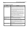
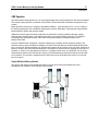
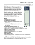
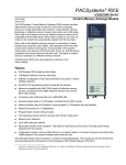
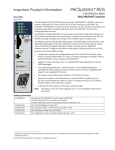
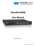
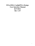
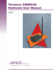
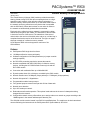
PACSystems™ RX3i
GFK-2506A
January 2010
IC695CMX128-AB
Control Memory Xchange Module
The Control Memory Xchange (CMX) module provides deterministic
sharing of data among PLCs and other computing devices on a highspeed fiber optic network, using reflective memory technology. A
reflective memory network can contain up to 256 nodes. Each node in
the network can be any reflective memory device that is compatible
with the 5565 family. When data is written to one node, all nodes on
the network are automatically updated with the new data.
Each node in the reflective memory network is connected in a daisychained loop using fiber optic cables. The transmitter of the first node
is tied to the receiver of the second. The transmitter of the second
node is tied to the receiver of the third node, and so on, until the loop is
completed back at the receiver of the first node. The figure on page 5
shows an example of a reflective memory network.
OK
CONFIG
SIG DETECT
OWN DATA
CMX128
NODE
A PACSystems RX3i main rack supports a maximum of six
CMX modules.
Features
■
PACSystems RX3i single slot form factor.
■
128 Mbytes reflective memory with parity.
■
Software configuration of all node parameters (no jumper or switch
settings required).
■
No RX3i CPU processing required to operate the network.
■
Network-compatible with VMIC 5565 family of reflective memory
devices, including the ACC-5595 reflective memory hub and the
RX7i CMX module.
TX (FRONT)
RX (BACK)
■
Connection with multimode fiber up to 300m/984.25ft.
■
Dynamic packet sizes of 4 to 64 bytes, controlled by the CMX module.
■
Network transfer rate of 43 Mbyte/s (4 byte packets) to 174 Mbyte/s (64 byte packets)
■
Network link speed of 2.1 Gigabits/sec.
■
Programmable module interrupt output.
■
Four general-purpose network interrupts with 32 bits of data each.
■
Network error detection.
■
Up to 256 nodes per network.
■
Redundant transfer mode operation. This optional mode reduces the chance of a data packet being
dropped from the network.
■
Configurable network memory offset allows you to assign nodes on a network to groups according to the
16MB segment in the network address space that they use.
The CMX128 module must be located in an RX3i Universal Backplane. The module can be hot-inserted and
removed following the instructions in the PACSystems RX3i System Manual, GFK-2314.
2
RX3i Control Memory Xchange Module
GFK-2506A
Specifications
Packet size
Transfer rate
User memory
Input power
(from RX3i power supply)
Dynamic packet sizes of 4 to 64 bytes, automatically controlled by the
CMX module
Network link speed of 2.1 Gbits/sec
128MB SDRAM
660 mA @ +3.3 VDC
253 mA @ +5 VDC
Connectors
■
Fiber optic LC type, conforms to IEC 61754-20
■
Zirconium ceramic ferrule
■
Insertion loss: 0.35 dB (maximum)
■
Return loss: -30dB
Refer to the PACSystems RX3i System Manual, GFK-2314, for product standards and general specifications.
Installation in Hazardous Locations
EQUIPMENT LABELED WITH REFERENCE TO CLASS I, GROUPS A, B, C & D, DIV. 2 HAZARDOUS
LOCATIONS IS SUITABLE FOR USE IN CLASS I, DIVISION 2, GROUPS A, B, C, D OR NONHAZARDOUS LOCATIONS ONLY
WARNING - EXPLOSION HAZARD - SUBSTITUTION OF COMPONENTS MAY IMPAIR SUITABILITY
FOR CLASS I, DIVISION 2;
WARNING - EXPLOSION HAZARD - WHEN IN HAZARDOUS LOCATIONS, TURN OFF POWER
BEFORE REPLACING OR WIRING MODULES; AND
WARNING - EXPLOSION HAZARD - DO NOT CONNECT OR DISCONNECT EQUIPMENT UNLESS
POWER HAS BEEN SWITCHED OFF OR THE AREA IS KNOWN TO BE NONHAZARDOUS.
Related Publications
PACSystems Memory Xchange Modules User’s Manual, GFK-2300
PACSystems RX3i System Manual, GFK-2314
PACSystems CPU Reference Manual, GFK-2222
Proficy™ Machine Edition Logic Developer-PLC Getting Started, GFK-1918
Ordering Information
Description
Catalog Number
Control Memory Xchange Module for RX3i
Fiber Optic Cables
IC695CMX128
VMICBL-000-F5-0xx,
where 0xx distinguishes different lengths
VMIACC-5595
Reflective Memory Hub
3
RX3i Control Memory Xchange Module
GFK-2506A
Release Information
This is the initial release of the RX3i Control Memory Xchange Module.
Release History
Release
Firmware
Version
Date
IC695CMX128-AB
1.02
IC695CMX128-AA
1.00
Upgrade Kit
Comments
October 2009
82A1512-MS10-000-A1
See “Problems Resolved.”
September 2008
N/A
Initial Release
Functional Compatibility
The CMX128 requires the following versions for configuration and operation.
Subject
Description
Programmer Version
Requirements
Proficy® Machine Edition Logic Developer 5.80 (released build
4541) or later is required to use the RX3i IC695CMX128 modules.
RX3i CPU
PACSystems RX3i CPU firmware version 5.50 or later
Rack Location
The CMX128 must be located in the main RX3i rack. IC695CMX128
modules require a PCI backplane, which is not available on
IC694CHSxxx expansion bases.
Problems Resolved by Release 1.02
Subject
Description
Memory read parity check
CMX/RMX memory read parity was checked only on DWORDs
aligned to QWORD boundary. An error existed in the parity check
where half of the memory was not being checked for parity. (Only
the lower 32-bit DWORD for each 64-bit QWORD would be parity
checked, ignoring the parity check on the upper 32-bits.)
CMX128 module power up
An error existed in the CMX transceiver control that allowed network
traffic to be received while the module was powering up and
executing internal initialization. Occasionally, this traffic could
interfere with the memory controller initialization, causing it to lock up
and preventing the module from completing power-up. The failure
occurred only when a Reflective Memory Hub was connected to
the CMX.
Eliminated possible
metastability issue in the
DDR2 memory interface.
An issue existed in the CMX DDR2 memory interface that could
cause the memory data path to be in a metastable state. If this
occurred, invalid data could be written to or read from the DDR2
memory.
4
RX3i Control Memory Xchange Module
GFK-2506A
Restrictions and Open Issues in this Release
Subject
RX3i CMX/RMX does not
disable transmitter when the
CPU goes to Stop/Halt mode.
The LCSR status bit is not
turning ON after LISR turns
ON when Interrupt (Sync Loss)
is generated
SVC_REQ 17 is not supported
CPU320 compatibility issue
with firmware version 5.50
Description
For IC695CMX128 modules and IC695RMX128 modules not used
as redundancy links, the automatic transmitter disable feature
currently does not work correctly when a controller goes to Stop/Halt
mode.
When the CPU goes to Stop/Halt mode or fails and the automatic
transmitter disable feature is enabled, the fiber optic transmitter
should be turned off, breaking the reflective memory link. When the
feature is disabled the transmitter remains ON and the reflective
memory link will not be broken.
When enabled, the automatic transmitter disable feature does not
work when the CPU goes into Stop/Halt mode (such as after a
software watchdog trip or multi-bit ECC error detection), leaving the
fiber optic transmitter ON. The fiber optic transmitter is properly
disabled if the CPU fails or is lost (for instance the CPU hardware is
removed, the CPU experiences a hardware watchdog event, or
displays a blink code such as a page fault).
This user-configurable feature is enabled by default. It may be
disabled by clearing bit 12 with a BUS_WRITE to region 3,
offset 0x440.
The LCSR bit is not latched to the ON state (indicating sync loss)
and should not be used for sync loss detection.
The LISR bit should be used for detecting sync loss.
SVC_REQ 17 is not supported to mask or unmask module interrupts
on RX3i CPUs. There is currently no way to identify which module
interrupt should be masked on RX3i. To turn off interrupts, use the
normal interrupt disabling mechanism described in the
IC695CMX128 user's manual. For details, see “Dynamic Masking of
Interrupts” in the PACSystems Memory Xchange Modules User’s
Manual, GFK-2300.
When using CPU320 with firmware version 5.50, occasionally, a
backplane reset of the CMX128 module will cause it to become nonresponsive. This problem is corrected in CPU320 firmware
version 5.51.
5
RX3i Control Memory Xchange Module
GFK-2506A
CMX Operation
The CMX module initially powers up in an unconfigured state with its optical transmitter and receiver disabled.
The module cannot operate on a network until the RX3i CPU has delivered a hardware configuration to the
module.
Basic operating functions are configured using Machine Edition – Logic Developer PLC. You can configure
the following parameters in the hardware configuration: Node ID, Redundant Transfer Mode, Rogue Master,
Network Memory Offset, and Interrupt enable.
Additional functions beyond the basic read and write operations, including enabling interrupts, reading
interrupt status, enabling parity, and reading parity errors, can be performed by user logic. For details on
accessing these advanced functions, refer to the PACSystems Memory Xchange Modules User’s
Manual, GFK-2300.
Once the CMX has been configured, a transfer of data over the network can be initiated by writing to the
reflective memory region through the backplane. The CMX forms the data into variable length packets sized
from 4 to 64 bytes, which it transmits over the fiber-optic network to the receiver of the next node. Whenever a
packet is received, the CMX evaluates the packet. If the packet is valid and did not originate on this node, it is
accepted. If, however, the data packet is invalid or if it originated at this node, it is discarded. The receiving
node writes the data into the local reflective memory and simultaneously transmits the data to the next node
on the network. The process is repeated until the data returns to the originating node, where it is removed
from the network.
Sample Reflective Memory Network
The seven-node network in the following illustration consists of six RX3i CMX modules and a PCI
WorkStation with a VMIPCI 5565 reflective memory board.
PCI WorkStation with
VMIPCI 5565 reflective
memory board
6
RX3i Control Memory Xchange Module
GFK-2506A
Optical Transceiver
The optical transceiver, which is located on the
bottom of the module, has two “LC” type fiber optic
ports. The port labeled “TX” is the transmitter and
the port labeled “RX” is the receiver.
CMX modules are networked together using either
simplex (single fiber) or duplex (dual fiber)
multimode fiber optic cables. The specific cable
construction depends on your operating
environment. For details on cables, refer to the
PACSystems Memory Xchange Modules User’s
Manual, GFK-2300.
LEDs
All front panel LED indicators are green.
LED Label
Optical
Transceiver
(bottom view)
Description
OK
ON indicates the CMX module and
the CPU are functioning properly.
CONFIG*
ON indicates the module is
configured.
TX
RX
SIG DETECT
ON indicates the receiver is
detecting a fiber optic signal.
OWN DATA
ON indicates the module has
received its own data packet from
the network at least once.
* A reflective memory hub can be used to bypass a node that is not configured.
Example of SIG DETECT Operation -- Node 5 Not Configured
Configured:
CONFIG ON
SIG DETECT ON
(if upstream node is configured)
Upstream
Nodes
RX
Node 4
TX
Not Configured:
CONFIG OFF
SIG DETECT ON
Configured:
CONFIG ON
SIG DETECT OFF
RX
RX
Node 5
TX
Node 6
TX
Downstream
Nodes