1
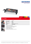
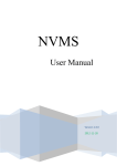
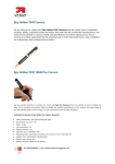
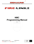
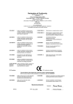
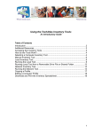
Wireless Hot Spot Gateway WAS-103R Quick Installation Guide Version 1.01 Quick Installation Guide WAS-103R Wireless Hotspot Gateway Preface Thanks to customers’ opinions on experiences of selling WAS-102R for several years. Due to global economy crisis and after discussing with some VIP customers, we are going to release a Light-weight but feature packed Wireless HotSpot Gateway by using the industrial standard hardware platform. PheeNet WAS-103R is a most economical Wireless HotSpot Gateway, and target for small venue, mini-size store with very user-friendly operation. Before, the business owner can make the money from the Wireless Internet Access providing. For the time being, the Wireless Internet Access is almost a kind of value added service. By take advantage of PheeNet WAS-103R, the front desk operator does not have to have enough IT technology, just identify the customer grade, offer the appropriate Pre-set ticket, and then charge the money (or not). In the mean time, the business owner or front desk operator will totally get rid of the hassle and time wasting on trouble shooting of Wireless HotSpot Gateway. With PheeNet WAS-103R, hotspot service is getting to a new generation, easier, more convenient, and more user-friendly. Package Contents WAS-103R x1 Ethernet Cable x1 5dBi Omni Antenna x2 Quick Installation Guide (QIG) x1 CD-ROM (with User Manual and QIG) x1 Power Adapter (DC 12V) x1 It is highly recommended to use all the supplies in the packege instead of substituting any components by other suppliers to guqrantee best performance. 2 Quick Installation Guide WAS-103R Wireless Hotspot Gateway System Overview Front Panel 1. 12V DC Injector : Attach the power cable here. 2. Reset Button : 3. Press and hold the Reset button for 2 seconds to restart system. The LED except Power indicator will be off before restarting. Press and hold the Reset button for more than 10 seconds to reset the system to default configurations. LAN1/ LAN2 (PoE) : In AP Mode : The LAN1/LAN2 port are for connection to external network or POE switch. In Hotspot Mode : The clients device with VLAN ID connect to LAN1 or LAN2 port. The port will be used by LAN port. Administrator can access the WMI (Web Management Interface) via this port LAN1 or LAN2 port is connected to external network. For example, it may connect to the ATU-Router of an ADSL, or the port of a Cable Modem. The port will be used by WAN port. 4. Console : The Serial RS-232 DB9 cable attaches here. Rear Panel WAS-103R supports 1 RF Interface with 2 SMA connectors for Antenna connection. LED Panel 1. WLAN : Green LED FLASH indicates Wireless ON, and FLASH quickly indicates Wireless Transmit quickly. 2. LAN1/LAN2 : Green LED ON indicates connection, OFF indicates no connection, and FLASH indicates The Port Transmit 3. PWR : Green LED ON indicates power on, and OFF indicates power off. 3 Quick Installation Guide WAS-103R Wireless Hotspot Gateway Hardware Installation Please follow the steps mentioned below to install the hardware of WAS-103R 1. Place the WAS-103R at a best location. The best location for WAS-103R is usually at the center of your wireless network. 2. Connect WAS-103R to your outbound network device. Connect one end of the Ethernet cable to the LAN1 port of WAS-103R on the front panel. On your environment, connect the other end of the cable to the external Internet . The LAN1 LED indicator should be ON to indicate a proper connection. 3. Connect WAS-103R to your network device. Connect one end of the Ethernet cable the LAN2 port of WAS-103R on the front panel. Connect the other end of cable to a PC for configuring the system. The LAN2 LED indicator should be ON to indicate a proper connection. 4. There are two ways to supply power over to WAS-103R I. Connect the DC power adapter to the WAS-103R power socket one the front panel. Please only use the power adapter supplied with the WAS-103R package. Using a different power adapter may damage this system II. WAS-103R is capable of transmitting DC current via its LAN1/LAN2 PoE port. Connect an IEEE 802.3af-compliant PSE device, e.g. A PoE Switch, to the LAN1/LAN2 port of WAS-103R with the Ethernet cable. Now, the hardware installation is completed. To double verify the wired connection between WAS-103R and your switch/router/hub, please check the LED status indication of these network devices. 4 Quick Installation Guide WAS-103R Wireless Hotspot Gateway Getting Started WAS-103R supports web-based configuration. Upon the completion of hardware installation, WAS-103R can be configured through a PC/NB by using its web browser such as Internet Explorer version 6.0. Default IP Address : 192.168.2.254 Default IP Netmask : 255.255.255.0 Default User Name and Password : admin/default Step 1. IP Segment Set-up for Administrator's PC Set the IP segment of the administrator's computer to be in the same range as WAS-103R for accessing the system. Do not duplicate the IP Address used here with IP Address of WAS-103R or any other device within the network Example of Segment : The value for underlined area can be changed as desired; the valid range is 1 ~ 254. However, 254 shall be avoided as it is already used by WAS-103R; use 10 as an example here. IP Address : 192.168.2.10 IP Netmask : 255.255.255.0 4. Login Success When administrator login success, the WAS-103R web management UI should be viewed at the Status section under the System Overview page 2. Launch Web Browser Launch as web browser to access the web management interface of system by entering the default IP Address, http://192.168.2.254, in the URL field, and then press Enter. 3. System Login The system manager Login Page then appears. Enter “admin” as User name and “default” as Password, and then click OK to login to the system. 5 Quick Installation Guide WAS-103R Wireless Hotspot Gateway Quick Setup WAS-103R is a two mode system which can be configured either as a Hotspot gateway or an access point as desired. This section provides a step-by-step configuration procedure for basic installation on AP Mode and Hotspot Mode Setup In AP Mode Step 1 : Mode Confirmation Ensure the Operating Mode is currently at AP mode; the web management UI can be viewed at the Status section under the System Overview page. Step 3 : LAN Interface Click System -> LAN, and then Network Setup page appears. Enable “Static IP” and “DNS”, and enter the related informations in the field marked with red asterisks. Click Save button to save the settings. Step 2 : Change Password Click System -> Management and then Admin Configuration page appears. Enter a new administrator's password in the New Password field, and re-enter it again in the Check New Password(a maximum of 32 characters and no space allowed). Step 4 : Time Zone settings Click Save button to save the settings. Click System -> Time Server, and then Time Server Setup page appears. Select an appropriate time zone from the Time Zone drop-down list to set up the system time. For security concern, it is strongly recommended to change the administrator's password Click Save button to save the settings. 6 Quick Installation Guide WAS-103R Wireless Hotspot Gateway For security concern, it is strongly recommended to set up Security Type with WPA-SPK or WPA2-PSK for Virtual AP Step 6 : Restart System Click Reboot to activate all settings configured so far. The Reboot message will appear on the screen during the restarting process. Step 5 : Wireless Interface Wireless General Setup Click Wireless -> General Setup, and then Wireless General Setup page appears. Select desired wireless Band, Transmit Rate and Channel for wireless interface. Please do not interrupt the system until the System Overview Page appears. Click Save button to save the settings. Congratulation ! The AP mode is now successfully configured. Virtual AP Setup Click Wireless -> Virtual AP Setup, and then VAP Setup page appears. Click “Edit” on VAP0 of Virtual AP List, and then VAP0 Configuration page appears. Select desired ESSID and Security Type for VAP0. Click Save button to save the settings. 7 Setup In Hotspot Mode Step 0 : Access to WAS-103R The default VLAN IP Address is between 192.168.100.1 to 192.168.107.1 and the IP Netmask is 255.255.255.0 The administrator's PC need support VLAN. Set VLAN ID 100 and set IP address automatically. The administrator PC's will be get IP address 192.168.100.xx (More VLAN Setting see User Manual) Open Browser and enter http:192.168.100.1 to access WMI of WAS-103R The switches deployed under WAS-103R must support VLAN or VLAN Passthrough Step 1 : Mode Confirmation Ensure the Operating Mode is currently at Hotspot mode; the web management UI can be viewed at the Status section under the System Overview page. Step 3 : WAN Interface Click System -> WAN and then WAN Setup page appears. Select a proper type of Internet Connection Type for WAN Interface from the following three available connections: Static IP, Dynamic IP, or PPPoE. Your ISP or network administrator can advise on the connection type available to you. Below depicts an example for Static IP. Click Save button to save the settings. Step 2 : Change Password Click System -> Management and then Admin Configuration page appears. Enter a new administrator's password in the New Password field, and re-enter it again in the Check New Password(a maximum of 32 characters and no space allowed). Click Save button to save the settings. For security concern, it is strongly recommended to change the administrator's password Quick Installation Guide WAS-103R Wireless Hotspot Gateway Step 5 : Generate HotZONE Ticket 's Passcode Step 4 : Wireless Interface Click HotZONE -> Generate Ticket, and then Generate Ticket Setup page appears. Select desired Ticket Database for HotZONE. Below depicts an example for Generate Ticket. Click “Generate” button to generate File ID “00000001” of Ticket Database Wireless General Setup Click Wireless -> General Setup, and then Wireless General Setup page appears. Select desired wireless Band, Transmit Rate and Channel for wireless interface. Click Save button to save the settings. Virtual AP Setup Click Wireless -> Virtual AP Setup, and then VAP Setup page appears. Click “Edit” on VAP0 of Virtual AP List, and then VAP0 Configuration page appears. Step 6 : Get Passcode on Ticket List Click HotZONE -> Ticket List, and then Ticket List page appears. Click “Info” of File ID to view Passcode. Below depicts an example for Passcode of File ID “00000001”. Select desired ESSID, Security Type and VLAN ID setting for VAP0. We select VLAN0 for this step. Click Save button to save the settings. For security concern, it is strongly recommended to set up Security Type with WPA-SPK or WPA2-PSK for Virtual AP 9 Step 7 : Create HotZONE With VLAN0 Click HotZONE, and then HotZONE Management page appears. Click “Edit” on VAP0 of HotZONE List, and then HotZONE0 Setup page appears. 3. Enter the Passcode of File ID “00000001” previously generated via Generate HotZONE Ticket's Passcode. Click “Login” button. (e.g. 43133335 ; you can get Passcode from Ticket List) Select desired setting for HotZONE0. Below depicts an example for Create HotZONE on VLAN0 and use File ID “00000001” of Ticket Database. Click Save button to save the settings. Congratulation ! The Login Page will redirected to www.pheenet.com and pop-on Timer Page after a client has successfully logged into WAS-103R and has been authenticated by the system. Step 8 : Restart System Click Reboot to activate all settings configured so far. The Reboot message will appear on the screen during the restarting process. The appearance of Login Timer Page means that WAS-103R has been installed and configured properly Please do not interrupt the system until the System Overview Page appears. Step 9 : User Login WAS-103R supports NTP time synchronization only, it is strongly recommended to make sure the NTP server is reachable and alive 1. Connect a client device (e.g. Notebook, PC) with wireless interface to scan the configured VAP0's ESSID of WAS-103R (e.g. “AP00”) and get associated with this ESSID. 2. The client device will obtain an IP Address automatically via VLAN0's DHCP from WAS-103R. Open a WEB Browser on a client device, access any URL, and then the HotZONE 0 User Login Page will appears. For further configuration and information, please refer to the User's Manual.