1
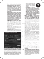
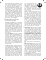
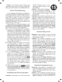
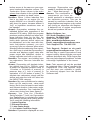
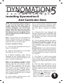
Installing Dynomation-5 And Cam/Lobe Data NOTE: This QuickStart guide is designed to give you the help you’ll need to quickly install and use Dynomation-5, 10-Point CamDisks, and Lobe-Profile Library disks. But when you have time, please review the main Dynomation-5 User Manual (open the manual by selecting User Manual from the HELP menu in the program). Note: In most cases, you can install any Motion Software product by following onscreen prompts. If you have any difficulty, please review the following steps: Program Installation Steps 1) Close all other applications before you begin an installation! 2) Insert the Dynomation-5 or a Cam data CD-ROM into your CD drive. 3) A Software Installation Menu will be displayed on your Desktop within 5 to 30 seconds. From the options provided in the menu, click the Install option. Note: If the Software Installation Menu does not automatically appear on your desktop within 30 to 60 seconds, doubleclick the My Computer icon on your desktop. Then double-click your CD Drive Icon (make sure the CD-ROM disk is inserted in your CD drive). Finally, doubleclick on Dynomation5_InstallMenu.exe (or other Program_InstallMenu.exe) to display the Installation Menu. 4) At the installer opening screen, click Dynomation, Version 5.08.0220, 2/09 Next to view the Motion Software License Agreement. Read the Agreement and if you agree with the terms, click I Accept..., then click Next to continue the installation. 5) A Readme file is now displayed that includes information about installation and program updates. After you have reviewed the Readme, click Next to proceed with the installation. 6) The next dialog indicates the recommended install directory and/or path. If you cannot install the program on the recommended drive or location, you can click CHANGE, and enter an alternate location. Important Note: If you install this software at other than the recommended location, updates or upgrades to this simulation may not install properly or function correctly on your system. 7) The Ready To Install screen gives you a chance to review your installation choices. Press Back to make any changes; press Install to begin copying files to your system. 8) When the basic installation is complete, a Setup Complete screen will be displayed. Click Finish to close this window and start additional helper-software installations: a) After the basic installation is complete, a dialog box may appear and ask for permission to install Microsoft DirectX on your system (DirectX is required 1 2 for Dynomation-5 3D animations). If you have the same or a newer version of DirectX already installed, the installer will detect its presence and will not overwrite newer files. b) Another dialog box may appear and ask for permission to install a Camtasia™ Codec on your system (needed to display tutorial and video help files). Choose Install to begin the codec installation. c) A final dialog box may appear and guide you through the installation of the HASP driver for the Dynomation-5 USB security key (discussed next). After the USB key driver has been installed, Dynomation-5 software installation is complete. 300-Page Color Users Manual Installing The USB Security Device 9) Install the USB Security Key (the small USB “plug” supplied with Dynomation) into any available USB port on your computer. This key is licensed to you, the purchaser of this software, and will allow you to run Dynomation-5 on any of your computer systems. You are licensed to install Dynomation-5 on as many computers as you wish, however, Dynomation-5 will only run on one system at a time; the computer with the Security Key installed. Note: If you do not have an available USB port (your computer must have at least one USB port to use Dynomation-5), you can install a USB Card or Hub to extend the number of available USB ports. The Dynomation-5 Security Key will function properly in USB ports directly attached to the computer or on an external USB Hub. Solving USB Security Key Issues If Dynomation-5 displays an error message that the Security Key or HASP is missing, here are some quick steps you can follow to isolate and correct this problem: a) Make sure the Security Key is, in fact, properly connected to a functioning This QuickStart guide will get you going, but to help you apply all the capabilities of this powerful simulation, a 300page, full-color, on-disk Users Manual has been included with this software. After installing Dynomation5, you can access the Users Manual by: 1) Opening the Help menu within Dynomation5 and selecting User Manual, or 2) Opening the Windows Start menu, select Programs, Motion Software Simulations, choosing Dynomation-5 Engine Sim, and finally clicking on the DynomationUsers Manual icon that appears within that folder, or 3) double click on the Dynomation-UsersManual.pdf file located on the Dynomation5 CD-ROM (in the root directory). IMPORTANT: If any of these techniques fails to open Dynomation documentation, you need to install Adobe Reader. The reader installation file is located in the Adobe Reader folder on the Dynomation CD-ROM. Simply double click on the program installer located in that folder to install Adobe Reader on Windows98/Me/NT/2000/XP/Vista/ Win7 systems. 3 USB port on your computer or has been plugged in a USB hub that is connected to your computer. If you plugged the Key into a hub (rather than into a USB port on the computer), try connecting it directly to a port on your computer system. Note: The Security Key contains a small LED that illuminates when it is properly connected and it has located the correct software drivers (these drivers are normally installed during Dynomation-5 installation, see step “c” below). b) Make sure your USB port is functioning correctly by disconnecting all other USB devices from your system. Then connect the Security Key (try a port you haven't used). If that works, try a different USB device in the port that did not work to determine if that port is defective. c) Try reinstalling the Security Key drivers by reinstalling Dynomation-5 from the program CD (you do not need to Un-Install first). d) If your computer is experiencing technical difficulties, such as non-functional devices, spontaneous rebooting, numerous error messages, etc., the device drivers for our Security Key may not be functioning properly on your system. You must have a “stable” computer system and a “clean,” virus-free Windows installation to properly use Dynomation-5. e) As a “last resort,” try installing Dynomation-5 and the Security Key on a second computer system to determine if your original computer is at fault. Installing A 10-Point CamDisk Library (Any Version) 10) CamDisks, additional libraries of (typically 6000+) 10-Point camfiles. If you wish to install a 10-point library (may be a separate disk or can be included on the Dynomation-5 CD), click the Install option on the Program Installation Menu (see page 1). CamDisk camfiles can only be installed after Dynomation-5 has been successfully installed on your system. Note: 10-Point camfiles are NOT the same as Lobe-Profile files; see page 10 for more information on camfile types and valve-motion modeling techniques in Dynomation-5 Installing A Lobe-Profile Library 11) Motion Software offers libraries of cam-lobe profiles that allow Dynomation-5 to model valve motion and predict engine power with the highest accuracy possible. Lobe-Profile Files consist of data that “maps” the entire shape of the lobe, not simply the valve opening, closing, and maximum lift points of 10-Point camfiles; see page 10 for more information on Cam-Lobe Profile usage in Dynomation5. If you wish to install any Lobe-Profile library, click on the Install option on the Program Installation Menu that will appear on your desktop after you insert the Profile CD into your CDROM drive (see page 1). Profile Libraries can only be installed after Dynomation-5 has been successfully installed on your system. Starting Dynomation-5 12) To start Dynomation-5, double-click the Dynomation-5 program icon that was installed on your Desktop. Alternatively, you can open the Windows START menu, select All Programs, then choose Motion Software Simulations, Dynomation-5 Engine Sim, and finally click on the Dynomation-5 icon displayed in that folder. USB Security Key Issues: If Dynomation-5 displays an error message indicating that the Security Key (HASP) is missing or cannot be found, refer to the information on page 2 for help. Automatic Program Updates 13) Dynomation-5 incorporates an automatic program updater that will keep your software current with the latest simulation developments. Before you put Dynomation5 to work, make sure you allow the Motion Updater to check our servers and install the latest program versions on your system (requires Internet connection). The Motion Updater will run automatically after initial 4 program installation and then approximately every 30 days thereafter. You can check for an update at any time by choosing Check For Newer Version... from the HELP menu within Dynomation-5. If you are unsure that the Motion Updater was able to download the latest release (or you suspect that you may have Internet connection issues), you can manually download the latest Dynomation-5 program updater/installer from the support page at: www.motionsoftware.com (perhaps using another computer or Internet connection). Important: Please make sure you are running the latest version of Dynomation-5 before you begin your engine development work. Don’t assume you are running the latest version if you just installed the software from the CD. CD’s are NOT updated each time new releases are issued by our development team. The ONLY way to make sure you are running the latest version is to use the Check For Latest Version feature (in the HELP menu) or to download the latest installer from our web site. Registering Dynomation-5 14) When you first start Dynomation-5, a Registration dialog will be displayed. Please fill in the requested information, including your Serial Number found below. Then press the Proceed button. If you have an Internet connection, your registration will be submitted to Motion Software, Inc. If you do not have an Internet connection, you will be presented with other registration options. If you do not register this simulation, you may not qualify for tech support or free updates. If you move or change your email address, you can update your registration information at any time simply by selecting Registration from the HELP menu in Dynomation-5. Keep up to date with the latest Dynomation advances by keeping your registration information current. A Short List Of Tech-Support Solutions Important Note: You can obtain technical support by sending an email to: support@ motionsoftware.com. We are here to help you get the most from Dynomation-5! 1) Dynomation-5 requires the entry of considerable information about your engine in order to perform a simulation. Input errors can generate invalid simulation results. Carefully review the data you have entered in the program (do a ProPrint™ printout to make the review easier). 2) Make sure you are running the latest version of Dynomation-5. Select Check For Latest Version... from the HELP menu in the program. 3) Select Show Simulation Log in the VIEW menu in the program. The log may help you track down out-of-range data or other non-fatal program errors. 4) Refer to FAQ’s on page 15 and in the main User Manual. 5) Contact technical support by sending an email to: support@motionsoftware. com. Include a detailed explanation of the problem and what lead up to the fault. Serial Number Required For Program Installation: Dynomation, Version 5.08.0220, 2/09 Dynomation-5 And Cam/Lobe Data QuickStart And Pro User Tips NOTE: This QuickStart guide is designed to give you the help you’ll need to quickly install and use Dynomation-5, 10-Point CamDisks, and Lobe-Profile Library disks. But when you have time, please review the main Dynomation-5 User Manual (open the manual by selecting User Manual from the HELP menu in the program). Thank you for purchasing Dynomation5™. This advanced engine simulation is the result of thousands hours of simulation and programming development and over twenty years of practical testing and validation. We are confident that this simulation package will help you further your understanding of engine dynamics and extend your ability to improve the performance of a wide variety of engines used in transportation, performance, and professional racing applications. What is dynomation-5? Dynomation is a Windows98/Me/2000/ XP/Vista/Windows7, engine-power (dynamometer) simulation consisting of two distinct engine simulation models: 1) A Filling-And-Emptying simulation that provides extremely fast mathematical solutions to engine physics, and 2) A full Wave-Action simulation that accurately predicts the complex pressure-wave dynamics and particle flow in intake and exhaust passages. The Wave-Action model picks up where the Filling-And-Emptying method leaves off and “homes in” on the best port sizes, shapes, 5 runner lengths, header-tubing sizes, and more, providing unprecedented simulation capability for the serious engine designer and builder. DYNOMATION-5 Requirements Here are the basic hardware and software requirements for Dynomation-5: • A Windows-compatible PC with a CDROM drive. • A USB Port for the Security Key is required to run Dynomation (see page 2). • A minimum of 128MB of RAM (random access memory) for Windows98/Me; 256MB for Windows2000/XP and 512MB for Vista and Windows7. • Windows98/Me or Windows2000/XP/ Vista/Windows7 (Windows95 is not supported). • A video system capable of at least 800 x 600 resolution. Recommend 1280 x 1024 or higher to optimize screen display of engine components and performance analysis graphics. • A fast system processor (2GHz or faster) will improve processing speeds; especially helpful for Wave-Action and Iterative™ testing. However, Dynomation-5 will operate on any qualified Windows system, regardless of processor speed. • A mouse. • Any Windows compatible printer (to obtain dyno-test printouts). THE MAIN PROGRAM SCREEN The left side of the Main Program Screen allows you to select simulation models, engine components, dimensions, and specifications. In addition, the right side of the main screen displays engine power curves and/or simulation results in graphical and chart form. The Main Program Screen is composed of the following elements (the numbers refer to the callouts in the photo on page 5): 1) 2) The Title Bar displays the program name followed by the name of the currently-selected engine. The Program Menu Bar contains pull- 6 down menus that control overall program function. Here is an overview of these control menus, from left to right: File—Opens and Saves Dynomation-5 test files, Imports other simulation files, Exports crank-angle and rpm-based engine test data, standard printing, advanced ProPrint™ reports, and contains a program-exit function. Edit—Clears all component choices. View—Allows you to display the Toolbar(3), Status Bar(8) and Workbook features. Also, lets you to select from several unique program color schemes. Simulation—Run forces an update of the current simulation. Auto Run enables or disables (toggles) automatic simulation calculation. You can also turn on or off a Simulation Log that displays diagnostic information about the simulation just completed. Units—Selects between US/Domestic and Foreign/Metric units. Tools—Opens the Iterative Testing window, the Cam Manager screen, or one of the other built-in, engine/ airflow/conversion calculators. Window—A standard Windows menu for arranging and selecting program display windows. Help—Gives access to the main Users Guide, Registration, and related program Update and Help features. 3) The Tool Bar contains a series of twelve (12) icons that speed up the selection of commonly used program functions and features. 4) The Simulation/Setup Category appears at the top of the Engine Component Categories(5), and is titled SIMULATION. Use this category to select the simulation model and make simulation-specific setup choices. 5) The Engine Component Categories are made up of the following groups: SHORT BLOCK—Select the bore, stroke, number of cylinders, piston pin-offset, and rod-length measurements in this category. CYLINDER HEADS—Select the cylinder-head type from generic choices or enter custom data. Direct entry of flowbench data (and up to three valves-per-port) is also supported. INDUCTION—Selects the intake manifold design, airflow rate and pressure drop through the induction system. Also select intake runner dimensions for the WaveAction simulation. In addition, this category allows the selection of forced-induction components. CAMSHAFT—Selects the camshaft type, activates V-V-T (variable valve timing), sets various cam timing/specifications, opens the CamManager™, Rocker-Math dialog, and allows Lobe-Profile data imports. Note: The CamManager™ is strictly a 10-Point cam-timing tool (see page 10 & 11) COMBUSTION—Selects the compression ratio, type of fuel, air/fuel Incomplete Component Fields All component categories start off empty, indicated by strings of asterisks (***) next to each incomplete component field. Move the mouse cursor into any category and click the left mouse button on the asterisks to open the component-specific menu. When all selections within a category are complete, the red Category Title Bar will change to green. 7 ratio, nitrous flow rate, combustion chamber design, and ignition timing. EXHAUST—Selects the exhaust-system configuration, runner and tubing dimensions and interconnection specifications. NOTES—Attach any comments/ notes about the current simulation in this category. Notes are saved with the engine .DYM file. Note: The Status of each Engine Component Category is shown by the color of its Category Title Bar. The Title Bars are either a red tone, indicating that the category is not complete (inhibiting a simulation run), or a green-tone indicating that all components in that category have been selected. 6a & 6b) The Main Program Screen window is divided into two panes. The bottom of the left and right panes display a set of Screen Display Tabs. Use these tabs to switch the left or right pane displays to component lists, tables, graphics, or other data displays. 7) Dynomation-5 can simulate several engines at once. Switch between open engines by clicking any Engine Selection Tab, located just above the Status Bar (see 8, below). 8) During data entry, the range of acceptable values and other helpful information will be displayed in a Range Limit Line within the Status Bar at the bottom-left corner of the screen. 9) Several component categories contain QuickAccess Buttons™ that give “one-click” access to important data-entry functions and calculators. 10) The widths of all program panes are adjustable with Vertical Screen Dividers and Horizontal Screen Dividers. 11) The Simulation Progress Indicator displays the progress of the selected simulation model as it computes engine physics throughout 720-degrees of piston movement (the entire fourstroke process). 12) The Crank-Angle SimData™ Window displays the exact values of port pressures, flow rates, horsepower, and more at various rpm and crank-angle points during Wave-Action simulations (open the SimData Window from the Tools drop-down menu). 13) The lower Port Velocity graph (velocity is default display—middle graph displays port pressures) shows port velocity at various rpm and crank-angle values during Wave Action simulations. Click on the top horsepower/torque graph to display a reticule line and establish the rpmdata-point for viewing pressure data. 14) The center Port Pressures graph (pressure is the default display—lower graph displays port velocities) shows port pressures at various rpm and crank-angle values during Wave-Action simulations. 15) The various graphs in Dynomation display horsepower, torque, port pressures, flow rates, valve lift, and more for the currently-selected engine. These graphic displays can be customized to display additional data in many formats using Graph Options Boxes. To display an Options Box, right-click on any graph. 16) The Horsepower And Torque (top graph default display) is shown for both WA and FE engine simulations and displays results throughout the simulation rpm range. Click on the graph to display a reticule line that fixes the rpm for viewing pressure/ velocity data on either the center or lower crank-angle graphs when using the Wave-Action model. 17) Each of the four graphs (the fourth is located “under” the Component Categories—to view this graph, click on the Graph Tab at the bottom of the left-side Window pane) incorporate a Reticule Line that appears when you click on the graph. You can “drag” the Reticule Line left and right, across the graph between the lowest and the highest test rpm (for rpm-based horsepower and torque graphs), or between 0- and 720-degrees of crankshaft rotation (for crank-angle/degree 8 based graphs). The exact values of the underlying data at the reticule intersections are displayed in the SimData™ Window (see item 12, above). 18) The Main Program Screen incorporates Windows Size Buttons. These buttons provide standard maximizing, minimizing, and closing functions. 19) The Pop-Up DirectClick™ Component Menus allow the selection of components and/or the direct-entry of specifications within each of the Component Categories. Click on any component specification to open its menu. If you wish to close the menu before making a new selection, click the red X next to the drop-down box or click anywhere outside the menu box. Direct-Input vs. Menu-Input Component Categories Component menus fall into two categories: 1) Those that accept direct user input (custom values) and, 2) those that only accept a selection from their attached drop-down menu. For example, the Number Of Cylinders menu in the ShortBlock category will accept direct input (any value from 1 to 12), but you can also select common cylinder combinations from the drop-down menu. When a menu supports direct-data entry, the component-entry bounding box will have a white interior (see photo, next page). On the other hand, the Pressure Drop menu associated with the Total Induction Flow Rate, will only accept one of the two selections from its attached menu (1.5- or 3.0-inHg). Data entry boxes within Component Categories that only accept menu inputs have a light-gray interior (as opposed to white). THE MEANING OF SCREEN COLORS Here is a quick reference to additional screen color functionality (these descriptions apply to the Dynomation-5 Blue color scheme; the default selection in the View menu. While other colors are used Drop-Down Component Menu ADDITIONAL FEATURES The Quick And Pro Iterators™ 9 Dynomation-5 incorporates the “ultimate” rapid-testing tool. The Quick Iterator™ (pronounced IT-TER-A-TOR) and ProIterator™. By clicking a single button, Dynomation-5 can perform a comprehensive series of engine tests to find optimum horsepower or torque for just about any application. Refer to the main User Manual for more information on using Motion Software Iterators built into Dynomation-5. A component box with a white background will permit direct numeric entry or a selection from the drop-down menu. A gray box will only accept a selection from the drop-down menu. Click on the red-X to close the dataentry box without making a selection. in different color schemes, the way these colors are used to differentiate component fields is the same): White: Most engine component field labels are displayed in white. This indicates that these fields contain data that is required in order for a simulation to be performed. Orange: Data in component fields that is displayed in orange indicates that these values are automatically calculated by program and cannot be directly altered. Light Blue (Cyan): All engine components displayed in light blue are specs that can be changed. For example, the Bore field in the SHORTBLOCK category is shown in Cyan and can be modified. BUILDING YOUR FIRST ENGINE A Five-Minute Tutorial is provided in the Main User Guide (see page 2). Also refer to OverView and Feature videos that may be supplied on the CD and are always available at: www.MotionSoftware.com. Compression-Ratio Calculator Dynomation allows the selection and testing of a wide range of compression ratios. Now you can directly enter combustion-chamber volumes, head-gasket thickness, etc., to determine their effects on engine compression. The Compression-Ratio Calculator quickly performs these functions. But this tool is more than a simple calculator, it “intelligently” adjusts itself to the needs of the engine builder, changing the way it functions depending on whether combustion volumes are known or need to be measured from engine components (open the Compression-Ratio Calculator from the Tools menu). The SimData™ Window The Crank-Angle SimData™ Window displays the exact values of port pressures and flow rates at various rpm and crankangle values. Click on any graph to display a reticule line. You can drag the reticule across the graph; the exact data values at the reticule intersections will be displayed in the SimData™ Window (open the SimData Window from the Tools menu). Rocker-Math™ Calculator The Camshaft Category includes a powerful Rocker-Math™ Calculator that will help you determine how and why changes in Rocker Ratio and Valve Lash 10 affect engine output (open the Rocker Math Calculator from the Tools menu). Important Rocker-Math Usage: Enter the original manufacturer’s (baseline) specifications for Rocker-Ratio and Valve Lash in the Camshaft Category FIRST! Then, after these basic specs have been entered, use the Rocker Math Calculator to determine how CHANGES to these stock specifications will affect cam timing, valve lift, and engine power. If you wish to “undo” changes made in the Rocker-Math Calculator (after they have been applied to the simulation), reopen the calculator and reenter the starting rocker ratio and lash values; do not enter counter-acting values in the Camshaft Category. manufacturer’s catalogs). But Dynomation-5 can also use the precise measurements of each lobe, called Lobe Profiles, to obtain the highest degree of modeling accuracy (see Lobe-Profile Libraries, on page 12). Cam modeling extrapolated from published valve-event timing is known as 10-Point Timing (since the data consists of 10 discrete data points per cam), while cam modeling derived from direct cam-lobe measurement is called Lobe Profile Timing and typically consists of 180 or more data points per lobe. USING CAM/LOBE DATA IN DYNOMATION-5 10-Point Timing, a term coined by Motion Software developers, indicates a particular camshaft is being modeled from ten, discrete data points: The Intake and Exhaust Opening and Closing points specified at both the Seat-to-Seat and 0.050-inch lift points (that’s 8 points) and the Maximum Lift of each lobe (that’s a total of 10 points of data), the 10 most commonly published timing points found in cam manufacturer’s catalogs). While this may be a small number of points to define both the intake and exhaust profiles of a camshaft, by using a few mathemati- Dynomation-5 is very versatile tool for modeling and testing cam timing and valve motion. It is well known for accurately modeling valve motion from basic “published” valve-event data (e.g., valve opening, closing, and lift points typically found in cam 10-Point Cam Timing 10-Point Vs. Lobe-Profile Timing Lobe-Profile Timing 10-Point Cam Data is a set of cam specs that describe both the intake and exhaust lobes of any particular cam. It includes seat-to-seat and 0.050-inch valve-event timing points. These eight values, plus the maximum lift of each lobe, add up to 10-data points for each camshaft. Dynomation can use 10-Point data to extrapolate valve-motion for any camshaft. Profile data is made up of lobe-lift data recorded at, usually, each degree of camshaft rotation (by installing the cam in a special measuring fixture). Dynomation-5 can use this data to very accurately determine valve positions at any point during the simulation. cal tricks, it’s possible to extrapolate an accurate valve-motion curve that offers a realistic approximation of valve-acceleration rates. Lobe-Profile Timing, on the other hand, consists of 180 points per lobe, is derived from actual measurements of cam lobes, and provides the most accurate representation of valve motion for any particular camshaft. Profile data can be considered the “final word” when it comes to testing a particular lobe set for real-world performance (other than using an actual dynamometer). Each of these cam-timing methods have their own advantages and disadvantages in engine simulation and modeling. For example, 10-Point models, while “datalimited,” can offer some advantages during engine development: 1) You simply may not have access to cam-profile data. In these cases, 10Point Timing is almost always easily found and allows reasonably accurate modeling. 2) Even if you have profile data, converting to 10-Point data (easily done in Dynomation-5) makes altering any individual timing point and determining the effects on engine output a simple mouse click. Profile data, while containing greater overall data accuracy, is considerably less flexible, since valve opening and closing points at any specific lift are “locked-into” the profile curve. By switching to 10-Point Timing, it’s a simple task to: a) manually alter any valve-event point, b) search and test any of the 6000+ 10-point camfiles supplied with Dynomation-5, or c) use the exclusive built-in Iterator™ to automatically test 10Point cam timing to determine what works in your application. While not as accurate as profile data in analyzing a particular lobe or camshaft, 10-Point Timing is a great way to ball-park or even zero-in on appropriate cam timing. Profile data then can be used to confirm the best “real world” intake and exhaust lobes for a specific application. Note: While you can not change individual valve-event timing points while using LobeProfile Timing, you can change lobe-profile centerlines. You can also “scale” lobeprofile data and change valve duration by altering the rocker ratio and valve-lash. For more about this, refer to Rocker-Math, on page 9; detailed information on RockerMath functions is provided in the main User Manual. 11 USING 10-POINT CAM DATA LIBRARIES Note: Refer to page 1 for help installing any Motion Software 10-Point CamData Library. A Motion Software CamDisk is a 10Point cam-data package (one is supplied free with Dynomation-5 on the CD). This library provides more than 6000, 10-Point camfiles that you can search and test in any engine. As mentioned previously, 10-Point simulations can be quite helpful during engine development, since you can tweak and tune individual valve events, which is not possible with Lobe-Profile data. The 10-Point CamManager™ Dynomation-5 incorporates a powerful valve-event manipulation tool: The 10-Point CamManager™. This comprehensive dialog was designed exclusively for 10-Point CamFiles. It will help you understand, analyze, create, and modify valve-event data for any engine application. Use the CamManager to load, import, save, and search for CamFiles™ (see the next section). Use the 10-Point CamManager to search and import CamDisk camfiles. This procedure is covered in detail in the main User Manual, but here are the basic steps to importing and using 10-Point Camfiles: 1)Open The CamManager™: The CamManager is the “central clearing house” through which you can load, save, and search for 10-Point CamFiles. Open the CamManager by clicking the CamManger button in the CamShaft Component Category. To load a Camfile, simply click the Open button within the CamManager and select the desired file from the File Open dialog box (.DCM, SCM, and .CAM Camfiles—various Motion Software 10-Point CamFiles—are all supported.) 2)Searching For 10-Point CamFiles: There are three Tabbed Data Pages (upper-center within the CamManager). The third tabbed data page provides considerable versatility in searching for CamFiles and locating those that meet your criterion. For example, you can find all the cams designed for a Honda, or locate all cams that closely match the valve-event specifications of the current engine. If you would like to search for specific filenames or cam descriptions, first enter any search terms into the Search For fields (multiple words should be separated by spaces). If you would like to locate CamFiles that fall within a range of timing values centered around the current camshaft timing, check the Find The Following Specs checkbox. Finally, click the Search button to locate all CamFiles starting in the folder listed in the Look In field and in any folders that are nested below that folder (a full recursive search for all .DCM, .CAM, and .SCM files is performed). Note: If you change any cam specification after retrieving a CamFile, the changed cam data WILL be saved with the engine (in the .DYM file) but will NOT be saved in a separate CamFile unless you specifically Save the modified cam data to a CamFile of your choosing, again using the CamManger. 12 obtaining the highest accuracy from Dynomation-5. Unfortunately, obtaining profile data in the past has been expensive and time consuming, requiring the purchase of one or more cams and physically measuring the lobes in a fixture. Now, Motion Software has introduced Lobe-Profile Library disks that contain thousands of profile files of actual production lobes, giving Dynomation-5 users substantial new advantages in engine testing and development. Importing profile data from a library takes only seconds. Here are some suggestions and tips that you may find helpful when using Lobe-Profile Libraries: 1)Where To Start: Each lobe-profile library includes a Lobe-Specification DataSheet (an Excel Spreadsheet) Motion Lobe-Profile Library CD USING LOBE-PROFILE LIBRARIES Note: Refer to page 1 for help installing any Motion Software Lobe-Profile Library. When you need to evaluate and select a specific cam for an engine, Lobe-Profile data, consisting of 180 or more data points measured directly from each cam lobe, ensures the highest valve-motion precision within the simulation. Since airflow into and out of the engine typically is very sensitive to valve position, especially at low valve lifts, profile data is an essential element in Another first for Dynomation-5 users are Lobe-Profile Libraries. Containing thousands of lobe profiles, they allow Dynomation to predict power with the highest accuracy. And they save time and money over manual lobe-measuring methods. that contains detailed information about each lobe. The DataSheet is installed in the Manuals & Videos directory under the main program directory (C:/ Dynomation5/Manuals & Videos). You’ll also find a link to this spreadsheet in the Windows program menu (START, All Programs, Motion Software Simulations, Dynomation-5 Engine Sim, Profile Library). The DataSheet contains design specifications and recommended applications for each lobe group or family. Use the spreadsheet as your starting point for locating an appropriate lobe combination for your engine. 2)Practical Advice And Pro-Tips For Picking A Lobe Set: a) Intake or Exhaust: Some lobes may be exhaust-specific and may not function well on the intake side, because of the slower closing ramps used on many exhaust profiles. However, intake profiles often work well on the exhaust side, in fact, engine builders regularly use intake profiles for exhaust valve actuation. In general, many of the most popular lobe profiles work well on both intake and exhaust valves. b) Family Matters: Typically the best cams are a mix of lobe profiles from two “families,” with a slightly quicker lobe on the intake side. However, many excellent cams are built from lobes within a single family (refer to the Lobe-Profile Spreadsheet that accompanies each Profile Library for details on lobe families). There are no hard-and-fast rules when it comes to lobe selection across all applications. c) Take It Slow: Top-performing lobe combinations have made their way into cam-manufacturer’s catalogs (some catalogs, such as the extensive catalog from COMP Cams included on their Lobe-Profile Library CD, list the lobe part numbers used to “build” each cam). While it may seem that cam companies would produce “catalog grinds” first, in reality many race and high-performance street grinds start off as custom lobes 13 that worked extremely well. We suggest that you start with baseline catalog grinds and then try a different intake or exhaust lobe, or change lobe centerlines. Start with something that is known to work and make incremental changes. Using our Lobe-Profile Libraries will not only give you the opportunity to optimize camshaft selection, but also you’ll be able to map out the sensitivity of your engine to changes. Taking modifications slowly will give you a much better feel for the “sweet spot” in your application. The way to optimize performance is not to start from scratch, but to start with something very good and then tweak it to make it great! Making well-documented, incremental changes through several iterations is what separates the very best engine builders (or cam guys) from the rest of the pack. 3)Importing A Lobe (see photo on page 14): Press the Import Lobe Profile button in the Camshaft Component category to begin the import process. When the file-open dialog appears, locate the lobe-library profile folder (typically: C:\Dynomation5\Cam Files\CamProfileFiles) and the specific folder for the library files (e.g., CompProfiles (.ecp)), then select a lobe and click OK. The Lobe Profile Import dialog will open to help you assign lobe data, adjust centerlines, and make other determinations about the data contained in the lobe profile. Here are key features of the Import Dialog: Lobe Source-Data List—A list of lobe data sets within the selected LobeProfile file are displayed in the top-left Source Data list. Some file types (like .S96, .ecp) will only contain single lobe data, while other files (like CamProPlus files) may have multiple lobe profiles included in the file. If multiple lobes are shown in the list, select one to apply it to other fields of the dialog. Lobe Duration—Duration Data lets you check LOBE duration at various lobe-lift points (please note that this usually is not be the same as Valve Duration). Values shown here should match the data in the accompanying spreadsheet. Lobe-Rendering—The lobe-profile image is rendered from the data recorded in the file. Use this image to confirm the validity of the data set (shows if points are missing, etc.) and to get a general “feel” for the nature of the lobe. The cam illustrated in the rendering is shown with a clockwise direction arrow, indicating that the opening flank is on the right side of the illustration and the closing ramp is on the left. Lobe-Data Destination—The lobe data can be assigned to either an intake or exhaust valve in the Lobe-Data Destination group. This data-entry area contains either two or four radio buttons, depending on whether Variable Valve Timing is being used. Lobe Centerline—Lobe-lift data is useless until it is “synchronized” with the crankshaft and piston movement. The Lobe Centerline indicates the rotational 14 index, in crank degrees, from the center of the lobe-profile data (point of maximum lift) to the Top-Dead-Center piston position. Note: You can change lobe centerlines after the lobe has been imported into the Camshaft Category. Convert To 10-Point Timing—Lobeprofile data can be “handed over” to the simulation in two ways: 1) You can directly import the “raw” valve-lift data into the simulation (this is the default method). Or 2) by checking Convert Profile Data To 10-Point Timing, you can force the conversion of Profile information into 10-Point timing data (see info about the differences between profile and 10-point timing on page 10). Note1: After you have imported profile data, you can still change to 10-Point Timing by simply clicking either of theConvertTo-10-Point buttons in the Camshaft Category. Lobe Profile Import Dialog The Import Lobe Profile Dialog will help you select lobe data, adjust centerlines, and make other determinations before you import lobe data in the simulation. The Lobe Source-Data List (upper left) displays all data sets in the file. If more than one is displayed, select one to apply its data to other fields in the dialog. The Lobe Lift/Duration group (lower left) lets you check the LOBE duration at various lift points. Use the Lobe-Rendering to confirm the validity of the data (shows if points are missing, etc.). The Lobe-Data Destination group (middle, top) lets you assign lobe data to either an intake or exhaust valve. The Lobe Centerline (middle, center) allows you set the profile rotational index, in crank degrees, from the point of maximum lift to the Top-Dead-Center piston position. Normally, lobe-profile data is passed directly to the simulation, however, by checking Convert Profile Data To 10-Point Timing you can force the conversion of Profile data to 10-Point Timing. Note2: The Profile Import Dialog will only import one lobe at a time; reopen the dialog to import data for an additional lobe. General Troubleshooting If you experience problems installing or using Dynomation-5, please make sure you are using the latest version of Dynomation (see #13 on page 3). You can contact technical support by sending an email to: [email protected]. Include a detailed explanation of the problem and what lead up to the fault. Dynomation is a complex program, and it’s easy to overlook data-entry errors. Here are just a few of the things you might think about when trying to solve problems: a) If you are not getting good correlation between the Wave-Action and FillingAnd-Emptying simulation models, make sure you are using similar induction and exhaust systems. Keep in mind that the Wave-Action model does not simulate mufflers (only open headers), so if you are using other than open headers in the Filling-And-Emptying model, power values will not match. b) If power values are higher for the Filling-And-Emptying model, try “tuning” the induction and exhaust systems in the Wave-Action simulation. The FillingAnd-Emptying model always assumes optimum runner and header lengths, so it often predicts “near optimum” power. c) If a turbocharging or supercharging system is not developing the boost or power you expect, remember that the Boost Limit in Dynomation is an upper limit. It does not force a too-large turbo to spin up more quickly and generate the desired boost. You need to select the correct size turbo, turbine, belt ratio, A/R ratio, etc., to obtain the desired boost curve. d) Take a few minutes to carefully review all your component selections. You may find that reviewing your engine component selections directs you to the source of the problem. Installation And General Operation Question: Encountered “Could not locate 15 HASP Security Key” error message when trying to run Dynomation. Answer: If Dynomation displays an error message indicating that the Security Key is missing or cannot be found, refer to page 3 for more information. Question: Dynomation produced an Assertion Failure error. What should I do? Answer: Please note down all of the information presented in the error-message box, provide a quick synopsis of what lead up to the error, then send this information, along with the engine file that created the problem, to Motion Software ([email protected]). Thank you for your assistance in helping us improve Dynomation. Screen Display Issues Question: Even though I have a 19-inch monitor, I can only see a portion of the Dynomation screen. Answer: The screen resolution of your monitor (not its size) determines how much of Dynomation you can see on screen without scrolling. You can change screen resolution by RIGHT CLICKING on your desktop, then selecting PROPERTIES from the drop-down menu. Choose the SETTINGS tab and increase screen resolution by moving the Screen Area slider to the right. Question: When I run a simulation, the values of horsepower and torque on the graph are not visible. What can I do to correct the display? Answer: Open the Graph Options menu (right-click on the graph) and select Auto Range for the X, Y1 or Y2 variable. See the main Users Manual for more information about graph scaling. Simulation Operational Issues Question: Dynomation calculated the total Combustion Volume at 92ccs. But I know my cylinder heads have only 75ccs. What’s wrong? Answer: This confusion comes from assuming that the calculated Combustion Space displayed in the component-se- lection screen is the same as your measured combustion-chamber volume. The Combustion Space volume is the entire volume that remains in the cylinder when the piston reaches top dead center. Question: When I chose induction flow that is too large for an engine (for example 4000cfm on a Honda 4-cylinder), why does the power increase without a “bog” or hesitation sometimes seen at low speeds? Answer: Dynomation maintains the established air/fuel ratio regardless of the selected CFM rating. While the program produces positive results from larger-andlarger induction flows (by the way, the predicted power increases are close to reality when optimum air/fuel ratios can be maintained, as is the case with electronic fuel-injection systems), you can’t go wrong if you use common sense when selecting induction/carburetor flow capacities. Also keep in mind that Dynomation-5 records and displays engine data after power output has stabilized, similar to testing methods used with a real dyno. Question: The engine I am building uses two carburetors. How can I simulate the airflow? Answer: Dynomation will simulate induction airflow from 100 to 7000cfm, rated at either the standard pressure drop of 1.5-inches or 3.0-inches of mercury (a pressure drop of 1 inch of mercury is equivalent to 13.55 inches of water). To simulate two carburetors, simply add the airflow and enter the total cfm value into the INDUCTION category. Question: My cam manufacturer’s catalog does not list seat-to-seat, valve-event timing. But it does list seat-to-seat intake and exhaust duration, lobe-center angle, and intake centerline. Can I calculate the valve-event timing from these figures? A n s w e r : Ye s . U s e t h e C a m M a t h QuickCalculator™ built into Dynomation (see Tools Menu) to calculate the intake and exhaust opening and closing points. You’ll need the following information: 1) Intake Duration 2) Exhaust Duration 3) Lobe-Center Angle. 4) And Intake Centerline Angle. Question: Dynomation displayed an error 16 message “Dynomation was unable to complete the simulation...” What went wrong? Answer: The combination of components you have selected produced a calculation error in the simulation process. This can be caused by restrictive induction flow on large-displacement engines or by radical cam timing on otherwise mild engines. A balanced set of engine components should not produce this error. Motion Software, Inc. 222 South Raspberry Lane Anaheim, CA 92808-2268 Voice Line: 714-231-3801 Web: www.MotionSoftware.com Email: [email protected] Tech Support Fax: 714-283-3130 Tech Support: Contact us via email: [email protected] This is the best way to reach Dynomation-5 tech support quickly. Always include your email address and attach any .DYM engine files that may help diagnose problems. Include a thorough explanation of the issues. Note: Tech support will only be provided to registered users. Please complete the Registration Form that appears when you first start your software to qualify for technical support from the Motion Software staff.