1
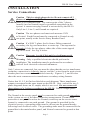
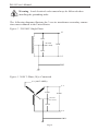
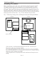
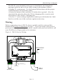
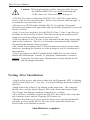
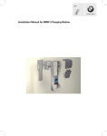
User’s Manual
•
•
•
•
•
•
•
®
ELECTRIC VEHICLE INFRASTRUCTURE, INC.
11839 INDUSTRIAL COURT ~ AUBURN, CA 95603
PLEASE NOTE
This user’s manual includes the latest information at the time of printing.
Electric Vehicle Infrastructure, Inc. (EVI) reserves the right to make changes to
this product without further notice. Changes or modifications to this product by
other than an authorized service facility could void the product warranty.
If you have questions about the use of this product, contact your customer
service representative. Refer to the Customer Support section located in this
guide.
DS-50 User’s Manual, PDF Version 2.1, December 2000
Copyright © 2000. Electric Vehicle Infrastructure, Inc.
All rights reserved. Printed in the USA.
DS-50 User’s Manual
CONTENTS
IMPORTANT SAFETY INSTRUCTIONS
Safety Guidelines . . . . . . . . . . . . . . . . . . . . . . . . . . . . . . . . .
1
OPERATION
Front Panel . . . . . . . . . . . . . . . . . . . . . . . . . .. . . . . . . . . . . .
In Case of Difficulty. . . . . . . . . . . . . . . . . . . . . . . . . . . . . . .
3
4
FEATURES
Personal Protection System . . . . . . . . . . . . . . . . . . . . . . .
Auto-Reclosure . . . . . . . . . . . . . . . . . . . . . . . . . . . . . . .
Off-Peak Charging . . . . . . . . . . . . . . . . . . . . . . . . . . . . .
Power Outage Restore . . . . . . . . . . . . . . . . . . . . . . . . . . .
External Error Indicator . . . . . . . . . . . . . . . . . . . . . . . . . . . .
Maintenance Current . . . . . . . . . . . . . . . . . . . . . . . . . . . . . .
5
5
5
5
6
6
INSTALLATION
Service Connections . . . . . . . . . . . . . . . . . . . . . . . . . . . . . . .
Mounting Procedures . . . . . . . . . . . . . . . . . . . . . . . . . . . . . .
Wiring . . . . . . . . . . . . . . . . . . . . . . . . . . . . . . . . . . . . . . . . . .
Testing After Installation. . . . . . . . . . . . . . . . . . . . . . . . . . . .
7
10
11
12
FOR THE SERVICE TECHNICIAN . . . . . . . . . . . . . . . . . . 13
SPECIFICATIONS . . . . . . . . . . . . . . . . . . . . . . . . . . . . . . . . . 15
WARRANTY INFORMATION . . . . . . . . . . . . . . . . . . . . 16
FCC INFORMATION . . . . . . . . . . . . . . . . . . . . . . . . . . . . . . 16
CUSTOMER SUPPORT . . . . . . . . . . . . . . . . . . . . . . . . . . . 17
MAINTENANCE . . . . . . . . . . . . . . . . . . . . . . . . . . . . . . . . . . 18
DS-50 User’s Manual
IMPORTANT SAFETY INSTRUCTIONS
Carefully read these instructions and the charging instructions in your
vehicle owner’s handbook before charging your electric vehicle.
The following symbols may be found in your handbook or on labels
affixed to your conductive charge station:
Note
This means pay particular attention. Notes contain helpful
suggestions.
Caution This symbol means be careful. You are capable of
doing something that might result in damage to equipment.
Warning This symbol means danger. You are in a situation
that could cause bodily injury. Before you work on any
electrical equipment, be aware of the hazards involved with
electrical circuitry and standard practices for preventing
accidents.
Safety Guidelines
• Use this charge station to charge electric vehicles equipped with a
conductive charge port only. See the vehicle’s owner’s handbook
to determine if the vehicle is equipped with a conductive charge port.
• Make certain the charge station’s supply cable is positioned so it will not
be stepped on, tripped over, or otherwise subjected to damage or stress.
• There are no user serviceable parts inside. Refer to the Customer Support
section in this manual for service information. Do not attempt to repair
or service the charge station yourself.
• Do not operate your charge station with a visibly damaged supply cable
or charge station. Contact your Service Representative for service
immediately. Refer to the Customer Support section in this manual for
information on the Service Representative in your area.
Page 1
DS-50 User’s Manual
Warning: Turn off input power to your charge station at the circuit
breaker panel before servicing or cleaning the unit.
·
Note
VENTILATION: Some electric vehicles require an external
ventilation system to prevent the accumulation of hazardous or
explosive gases when charging indoors. Check the vehicle’s owner’s
handbook to determine if your vehicle requires ventilation during
indoor charging.
Those vehicles which follow the SAE J1772 standard for communication with the charging station can inform the DS-50 that they require
an exhaust fan. The DS-50 is not equipped to control ventilation fans.
If an exhaust fan is requested, the DS-50 will not charge the vehicle.
If this function is required, ask your EVI representative for information on the EVI® ICS-200B, which has the exhaust fan control feature.
Caution: DO NOT charge your vehicle indoors if it requires
ventilation. Contact your Service Representative for information.
Page 2
DS-50 User’s Manual
OPERATION
The DS-50 Electric Vehicle Charging Station is a conductive charge station that
provides the electric vehicle (EV) user with a safe and manageable link between
the power grid and the EV.
Figure 1. The DS-50 Charging Station
The DS-50 Electric Vehicle Charging Station is very easy to use. Just remove the
charging connector from its holder on the front of the charging station, and plug it
into the vehicle’s charge port. Upon insertion, push down on the handle to lock it
into place. Normally, the vehicle will immediately request a charge using a
special communication line in the cable, and the contactor inside the DS-50 can
be heard closing. The green Charging light will come on, and charging will begin.
After an average driving day, it will require several hours to recharge completely.
Charging overnight is the most convenient way to maintain healthy batteries and
ensure the vehicle’s full range will be available for the next day.
To remove the connector from the vehicle, depress the button in the middle of the
handle to release the connector. When not in use, store the connector in the
DS-50’s front panel holder.
Front Panel
The front panel has a GREEN and a RED light to indicate the status of the DS50. The operational state of the unit can be known just by looking at the two
lights, and comparing them with table 1 on page 4.
Page 3
Table 1. Front Panel Indicators
(Gre e n)
(Re d)
CHARGING
PROTECTION
--
--
not connected, or vehicle not requesting charge
lit
--
charging
--
lit
ground fault tripped, or service required
lit
lit
problem on vehicle
blink
--
charge disabled, or Power Outage Restore mode
STATUS of DS-50
Note: in the table above, a (--) symbol indicates the LED is off.
In Case of Difficulty
EVI recognizes that this Charging Station will be heavily relied upon to charge
your electric vehicle for daily transportation needs. Therefore, every effort will
be made to restore service should problems arise.
In the event of a problem, charging will stop and the red Protection light will
come on. If this happens, please try the two simple steps below before calling
your Field Service Representative.
1. Remove the cable connector from the vehicle socket. The red Protection light
may go out. If it does go out, plug the connector back into the socket, and see if
charging begins normally. If it doesn’t charge, call for Field Service.
2. If the red Protection light does not go out when the connector is removed, be
sure the connector is removed from the vehicle socket and switch off power at
the circuit breaker feeding power to the DS-50. Wait a few seconds and switch
the circuit breaker back on again. If the Protection light does not come back on,
re-connect the cable to the vehicle. Charging should begin normally. If
charging does not begin, call for Field Service.
The information gained by the above steps will help the Field Service Representative decide what the problem is, and how best to get your DS-50 operational
again as quickly as possible.
Page 4
DS-50 User’s Manual
FEATURES
The following features are supported by the DS-50:
Personal Protection System: Ground Fault protection with Self-Testing
and Auto-Reclosure (see below), no manual resetting or testing is
necessary.
Ground Monitoring Circuit: Constantly checking for the presence of a
Safety Ground connection.
Auto-Reclosure: If a problem occurs that interrupts charging, the unit will
automatically clear all error indications after 5 minutes, and attempt to
begin charging again. If the problem is immediately sensed a second time,
it will wait another 5 minutes and try again. This process will repeat several
times, at which point power will be removed and no further attempt will be
made. The red front panel Protection LED will be lit.
This feature helps ensure that your vehicle will be charged and ready for
use when needed. Temporary problem indications such as ground-faults or
utility power surges can be overcome automatically without the need for the
user to manually re-initiate charging.
Off-Peak Charging : for this feature, you must have an external timer
installed (purchased separately), and also have your local utility install a
special Time of Use meter. Many utilities plan to give very low rates to
those EV owners who charge in the late evening. If a timer is installed, you
do not have to wait until the late evening to plug the DS-50’s connector into
the vehicle. You may plug in at any time. Even though the vehicle may
immediately request a charge, the timer will cause the DS-50 to delay
energizing the cable until the off-peak hours when most electric utilities
have light demand. With this feature, the green Charging light will be
flashing while the vehicle is waiting for the timer to allow charging.
If this feature is desired, please call your local utility to be sure the Time of
Use meter is available in your area before having the timer installed.
Technical information to help the installer connect the timer to the DS-50
can be found in the section titled Specifications on page 15 in this manual.
Power Outage Restore: This feature is built-in to the DS-50, but will only
be apparent when the utility power fails during charging. If the charging
connector is still plugged into the vehicle when utility power is restored, the
unit will blink the green Charging light and not energize the cable for a
random time between 2 and 12 minutes. This is to prevent the utility’s grid
from experiencing a large surge at turn-on, allowing EV’s in the area to
begin drawing current at random times rather than all at once.
Page 5
DS-50 User’s Manual
The user does not need to be concerned that the vehicle needs attention
after a power outage. The DS-50 will automatically resume charging when
power is restored.
External Error Indication: Whenever the red Protection LED is lit, a relay
on the board will provide a contact closure that can be used to remotely
indicate that a problem exists. A fleet vehicle yard, for example, could use
this feature to light a lamp or ring a bell in the main office, letting them
know immediately that a vehicle is not charging. This early warning helps
assure that each vehicle will be properly charged and ready for use when
needed.
Maintenance Current: If the unit is set up for Off-Peak Charging as
described above, no current can be drawn by the vehicle until the Off-Peak
hours. However, the DS-50 can also be set up to allow a minimum amount
of current while waiting for the timer to allow full-rate charging. This is
known as Maintenance Current, used for all power needs on the vehicle
except charging the main battery pack. An example would be preheating
the cab, or keeping the auxiliary battery topped off. As in the Off-Peak
mode above, the green Charging light will flash if the vehicle is connected
and waiting for the timer to allow charging. The contactor will close
immediately to supply this small amount of power, but the main battery
pack will not be allowed to charge.
The Maintenance Current feature can be enabled and disabled using a
jumper on the PC board labeled CMELD. This is a 2-pin jumper located to
the right of the Charge Test buttons. The DS-50 is shipped from the factory
with Maintenance Current enabled, with the jumper in place. To take
advantage of the feature will require the following:
1. Installation of a Time-Of-Use meter by the electric utility.
2. Installation of a clock/timer to only allow the DS-50 to
charge during the Off-Peak hours.
Please refer to Service Bulletin number 200001001 on EVI’s website @
www.evii.com for additional information on the Maintenance Current
feature. From our Homepage, just click on the Download Area and scroll
down to Service Bulletins.
Page 6
DS-50 User’s Manual
INSTALLATION
Service Connections
Caution This is a single-phase device. Do not connect all 3
phases of a 3-phase feed !!! You may use any two phases of a 3phase wye-connected feed. The center-point of the 3 phases
(usually used as Neutral) must be grounded somewhere in the
system. A current-carrying Neutral is not needed by the DS-50.
Only Line 1, Line 2, and Ground are required.
Caution The two phases used must each measure 120V
to Neutral. Earth Ground must be connected to Neutral at only
one point, usually at the Service Entry Breaker Panel.
Caution If a 208V 3-phase feed is from a Delta-connected
secondary, the leg used must have a center-tap. That tap must be
Grounded. Only the two phases either side of the center-tapped
leg can be used. See Fig. 4 below.
Caution Warranty is void if this unit is wired improperly
Warning Only a qualified electrician should perform the
installation. The installation must be performed in accordance
with all local electrical codes and ordinances.
Only 3 wires are connected, but care must be taken that the service transformer
secondary connection is definitely known, and the 3 wires from the main circuit
breaker panel are connected and labeled correctly. Figures 2, 3, and 4 below
show the most common service transformer secondary wiring formats.
Notice that L1, L2, & Gnd are labeled on each diagram. Those transformer
outputs correspond to the same inputs on the DS-50. Also, each of the two 3phase diagrams shows an L3 output, which is not used. Do not connect all
three phases of a 3-phase secondary to the DS-50. This is a single-phase
device.
The Neutral at the service panel must be connected to earth ground somewhere
in the system on any of the three connection arrangements. Ground-fault
protection is not possible unless the Neutral (center-tap on the service transformer) is connected to an earth ground. If no ground is provided by the
electrical service, a grounding stake must be driven into the ground nearby,
following local electrical codes. The grounding stake must be connected to the
ground bar in the main breaker panel, and Neutral connected to ground at that
point.
Page 7
DS-50 User’s Manual
Warning Local electrical codes must always be followed when
installing the grounding stake.
The following diagrams illustrate the 3 service transformer secondary connections most common in the United States.
Figure 2. 220/240V Single Phase
L1
120V
NEUTRAL
(NOT USED)
240V
120V
L2
GND
Figure 3. 208V 3-Phase, Wye-Connected
L3 (NOT USED)
L1
120V
208V
NEUTRAL
(NOT USED)
120V
L2
GND
Page 8
DS-50 User’s Manual
Note
With a wye-connected secondary, any two of the legs can be used
to provide 208V to the DS-50. For example, L1 & L2, or L1 &
L3, or L2 & L3. Leave the unused leg open. Do not connect it to
a Neutral bar, or to Ground. Be sure the center point is grounded
to earth somewhere in the system.
Figure 4. 208V 3-Phase, Delta-Connected, with center-tap on one leg.
L3 (NOT USED)
L1
120V
208V
NEUTRAL
(NOT USED)
120V
L2
GND
Caution With the delta connection, one leg must be centertapped, and only the two phases on either side of the center tap
can be used. The two phases must both measure 120V to neutral.
The third line (L3) of the delta is 177V, with respect to neutral,
and is sometimes referred to as a “stinger”. Do not use this third
line! Also, when using the center-tapped leg in this fashion,
the power rating for that leg alone is much less than the power
rating of the entire transformer. Consult the transformer
manufacturer’s literature to be sure the single leg can supply the
required current.
Caution A 3-phase delta-connected transformer secondary
without a center-tap on one leg is not usable with the DS-50. No
“neutral” point is available to be connected to ground for groundfault protection, and the DS-50 will not allow the contactor to
close if it does not sense the presence of a ground wire connected
to a “neutral” point on the transformer secondary.
Page 9
DS-50 User’s Manual
Mounting Procedures
Before installation, remove the screw at the bottom of the front panel, turn the
front panel upside down, and re-insert the screw to hold the panel out of the
way. This provides support to the LED wires going from the front panel to the
PC Board. They can also be disconnected and the panel completely removed if
desired, but the three connections must be carefully noted to be sure they are reinstalled correctly later. Be sure not to pinch the wires between the panel and the
bottom lip of the enclosure base. Fig. 5 below illustrates the procedure.
Fig. 5. Removing, turning, and re-attaching the front panel during installation.
AFTER
BEFORE
Charging
Protection
PANEL
LED
WIRES
PC BOARD
Remove Screw Here
Protection
Charging
• Be sure there is solid structural support for the unit – do not rely on
sheetrock or other non-structural support.
• Use the drill template provided – do not use the box as its own template.
Do not drill through the box mounting holes into the wall. Keep the interior
of the box as free of debris as possible.
• Do not punch rear or top-entry holes in the enclosure to bring in service
wiring.
Page 10
DS-50 User’s Manual
The DS-50 is not intended for this type of installation, and component
spacings inside the unit will not allow wiring in this manner without
violating UL requirements. Use the bottom-left knockout with the proper
conduit from the circuit breaker panel.
• Locate the bottom of the enclosure 38 inches above ground. Also, the
unit should be placed to allow the 22-foot charging cable to easily reach
and connect to the vehicle’s charging port.
• Use the ¼” water-sealing compression washers provided under the 4 bolt
heads to seal the rear of the enclosure against water entry.
Wiring
Before connecting wires to DS-50, please carefully read the section of this
manual titled Service Connections, on page 7. If you are unsure of the type of
power provided at the service panel, please consult with your local utility or call
your Field Service Representative for assistance.
Figure 6. DS-50 Service Wiring
Brown
Black
L1
RED
L1
Contactor
PWR
OUT
PWR
IN
L2
L2
BLACK
Black
Brown
Be sure RED and BLACK
wires both go through the
CCID sense coil
PC BOARD
LEDS
CCID
Sense Coil
CHARGE
TEST
Blue
Pilot
GND
GND
Blue
GREEN
Gnd Terminals
Violet
Yellow x 2
Charge Disable
(Ground to Disable Charging)
External Error
Relay Contacts
Cable to
Vehicle
From
Service Panel
Page 11
DS-50 User’s Manual
Caution: When replacing the vehicle charging cable, be sure
the RED and BLACK wires both go through the
CCID sense coil. Refer to Fig. 6 on page 11.
• The DS-50 requires a dedicated 208/240 VAC 50/60 Hz, single phase
circuit, with its own circuit breaker. Refer to the Current chart on page 15
to determine circuit breaker size.
• Do not use a GFCI breaker with the DS-50. It contains a Personnel
Protection ciruit that is the equivalent and specifically designed for use with
electric vehicles.
• Only 3 wires are needed to wire the DS-50 (Line 1, Line 2, and Service
Ground), as shown in Fig 8 above. Wire the unit from the breaker panel
using wire sized according to local electrical codes.
• The two phases (Line 1 & Line 2) are terminated in the large wiring lugs
right on the contactor. The Service Ground is terminated in the Ground
Terminal at the bottom of the enclosure.
• Be careful not to damage the PC Board when removing the power-entry
knockout, attaching the conduit, or when wiring the service conductors to
the contactor.
• The 2-pin jumper on the PC board labeled CMELD is used to enable/
disable the Maintenance Current. If jumpered, Maintenance Current is
enabled. Generally, for most users, Maintenance Current should be left
enabled, with the jumper installed.
Testing After Installation
• Apply utility power, and observe that only the Diagnostic LED is flashing
on the circuit board, at a ½ sec rate. If it is not flashing, the board could be
defective.
• Push both of the Charge Test buttons at the same time. The contactor
should close, and the green Charge LED on the front panel should light.
The Charge Test buttons simulate connection to a vehicle.
• If a vehicle is available, connect the DS-50 to the vehicle and verify that
the contactor closes and the Charging LED comes on.
• Remove the front cover screw, turn the front cover around and install it
normally to close up the DS-50. Be sure not to pinch the small wires
between the cover and the enclosure.
Installation is complete.
Page 12
DS-50 User’s Manual
FOR THE SERVICE TECHNICIAN
There are 6 LEDs on the PC board to help diagnose problems:
Diagnostic – this is the “heartbeat” of the system. When only this LED is
slowly flashing, the system has not detected any failures. If it is lit but not
flashing, the board is defective. If it is not lit, either no power is applied or the
board is defective.
To test the system, press and hold both Charge Test buttons simultaneously. If
the contactor closes, the DS-50 is operating normally. If a vehicle is available,
connect the charging cable. The contactor should close. If not, the charging
cable or vehicle socket may be defective, or the vehicle is not requesting a
charge.
If the DS-50 detects an internal failure, the Diagnostic LED will blink at a faster
rate. One of the other LEDs may indicate the nature of the problem.
Charge: Lit, and not flashing, when the contactor is closed and the vehicle is
charging normally. It will be flashing when the vehicle is connected while the
DS-50 is in either of two modes:
• Power Outage Restore mode, after a power outage, waiting for a random
2-12 minute interval to pass before re-initiating charging.
• External Timer mode, waiting for the timer to indicate an Off-Peak
Charging time is available.
Charge Disable: Lit when either the Power Outage Restore or External Timer
mode mentioned above is active. Both the board and front panel Charge LEDs
will be blinking.
GFCI Trip: Lit when the unit has detected a ground fault. The contactor will
open, the front panel Protection light will also be lit, and the Diagnostic LED
will be flashing at a faster rate. The system waits 5 minutes after sensing a fault,
then automatically attempts recovery. After several such attempts, it will stay in
the Protection mode.
If a ground fault error or an EV connection error has been detected:
1. Remove the EV connector from the vehicle
2. Inspect the connector and the vehicle’s charge port. Be sure they are
clean and undamaged.
3. Reconnect to the vehicle. If the fault condition persists, a problem may
exist on the vehicle.
Page 13
DS-50 User’s Manual
3. Refer to the vehicle owner’s manual for instructions on inspecting and
cleaning the charge port.
4. Plug the EV connector back into the vehicle.
5. If the ground fault error is still detected, contact your customer service
representative for assistance.
Ground Missing: Lit when the unit has detected a missing Service Ground.
The DS-50 will not close the contactor unless a proper Service Ground is
connected. The front panel Protection light will also be lit, and the Diagnostic
LED will be flashing at the faster rate.
NOTE: If a missing ground is discovered, power must be turned off before
re-connecting the ground. If this is not done, it will be necessary to wait 5
minutes for the DS-50 to clear the Ground Missing error.
Service: Lit when the DS-50 detects a failure in either itself or the vehicle. To
troubleshoot, be sure the charging cable is disconnected from the vehicle, and
reset the DS-50 by turning the power off and back on at the breaker panel
feeding the DS-50. If the Service LED remains lit, the DS-50’s PC board has a
problem, and should be replaced to restore service as soon as possible.
Table 2 below illustrates the information that can be obtained from the 6 LEDs.
Note: a (--) symbol indicates the LED is off.
Table 2. PC Board Diagnostic LEDs
LED 1
Status
LED 2
LED 3
LED 4
LED 5
LED 6
Diagnostic
Charge
Blink Rate
CCID
Trip
Ground Charge Service
Missing Disable Required
Normal Operation
slow
--
--
--
--
--
Charging
s l ow
lit
--
--
--
--
Charge Disabled
slow
blink
--
--
lit
--
Cold Load Pickup
slow
blink
--
--
lit
--
CCID Trip
fast
--
lit
--
--
--
Vehicle Error
fast
lit
--
--
--
lit
Ventilation Requested
fast
lit
--
--
--
lit
Ground Missing
fast
--
--
lit
--
--
Unit or Vehicle Service
fast
--
--
--
--
lit
Page 14
DS-50 User’s Manual
SPECIFICATIONS
Input Power - Service Entrance
Voltage & Wiring
240V AC single-phase -L1, L2, and Safety Ground
208V AC 3-phase, wye-connected - Any 2 phases,
and Safety Ground
208V AC 3-phase, delta-connected. With centertap on one leg, must use only the two phases on
either side of the center-tap. The two phases must
both measure 120V AC to ground. Do not use the
third leg (177V “stinger”).
Current
Continuous
Vehicle Current
Breaker
Size
DS-50
Part Number
16A, or less
20A
DS50-20-S2-10
24A, or less
30A
DS50-30-S2-10
32A, or less
40A
DS50-40-S2-10
Frequency
50/60 Hz
Output Power
Variable depending on vehicle. Current vehicles
typically draw approximately 5 KW.
Dimensions
Height
Width
Depth
Cable Length
244 mm (9.6 in)
203 mm (8 in)
157 mm (6.2 in)
approximately 6.8 m (22 ft)
Weight (with Cable)
7.7 kg (17 lbs)
Environment
Operating Temperature
NEMA Rating
-40°C (-40°F) / +60°C (+140°F)
3R; outdoor use with rain, snow, and sleet conditions.
External Connections
Charge Disable
Ground to disable charging, leave open to charge.
12 volts with 1K source resistance when open circuit,
12 ma sink current when grounded.
Error Relay Contacts
24V AC or DC, 5A max current, closed if error present.
Agency Approvals
UL Listed, FCC Class B
Color
Gray
Page 15
DS-50 User’s Manual
LIMITED WARRANTY – ELECTRIC VEHICLE SUPPLY EQUIPMENT
MODEL DS-50
ELECTRIC VEHICLE INFRASTRUCTURE, INC.
11839 Industrial Court
Auburn, California 95603
Service: 877-438-3844 (EVII)
EVI shall provide the following warranty with respect to the Products to
representative, its Sub-Representatives and their customers:
Product 3-years parts, 3-years factory labor, 1-year in field service for unit,
cable, and connector
Electric Vehicle Infrastructure, Inc. (“EVI”) warrants this electric vehicle
charging product to be free from defects in material, manufacture and design for
the period specified after the date of the first installation. If this product is
defective in materials, manufacture or design during this warranty period, EVI
will, at its option, repair or replace the product. Repair parts and /or replacement
products may be either new or reconditioned at EVI’s discretion. This limited
warranty does not include service to repair damage from improper installation,
improper connections with peripherals, external electrical fault, accident,
disaster, misuse, abuse or modifications to the product not approved in writing
by EVI. Any service repair outside the scope of this limited warranty shall be at
applicable rates and terms then in effect. All other express and implied warranties for this product including the warranties of merchantability and fitness for a
particular purpose, are hereby disclaimed. Some states do not allow the exclusion of implied warranties or limitations on how long an implied warranty lasts,
so the above limitation may not apply to you. If this product is not as warranted
above, your sole and exclusive remedy shall be repair or replacement as
provided above. In no event will EVI, any of its authorized sales and service
representatives, or its parent company be liable to customer or any third party
for any damages in excess of the purchase price of the product. This limitation
applies to damages of any kind including any direct or indirect damages, lost
profits, lost saving or other special, incidental, exemplary or consequential
damages whether for breach of contract, tort or otherwise or whether arising out
of the use of or inability to use the product, even if EVI or an authorized EVI
representative or dealer has been advised of the possibility of such damages or
of any claim by any other party. Some states do not allow the exclusion or
limitation of incidental damages for some products, so the above limitation or
exclusion may not apply to you. This warranty gives you specific legal rights,
and you may also have other rights which may vary from state to state.
Page 16
DS-50 User’s Manual
To obtain warranty service:
Call your nearest authorized service provider or EVI at the above number. You
will receive information as to how service for the product will be provided. If
the product is installed at a location which is more than 75 miles from the
nearest authorized service provider business location you may be required to
mail or ship the product to a designated service center or pay for a service
technician to provide service at the installation site. If you mail or ship the
product in for service, you must insure the product, prepay all shipping charges,
and properly pack it for shipment in its original shipping container or its
equivalent. You are responsible for all loss or damage that may occur in transit.
You must provide proof of purchase of the product and the purchase date before
any warranty service can be performed.
FCC INFORMATION
This device complies with Part 15 of the FCC rules. Operation is subject
to the following two conditions: (1) This device may not cause harmful
interference, and (2) This device must accept any interference received,
including interference that may cause undesired operation.
This product has been designed to protect against Radio Frequency
Interference (RFI). However there are some instances where high
powered radio signals or nearby RF-producing equipment (such as
digital phones, RF communications equipment, etc.) could affect
operation.
If interference to your charge station is suspected, we suggest the following
steps be taken before consulting your EVI Sales and Service Representative
for assistance:
1. Reorient or relocate nearby electrical appliances or equipment
during charging.
2. Turn off nearby electrical appliances or equipment during charging.
Caution Changes or modifications to this product by other than
an authorized service facility could void FCC compliance.
Page 17
DS-50 User’s Manual
CUSTOMER SUPPORT
Call your EVI® Service Representative at any time, 24 hours a day, at the
number below. PLEASE HAVE THE MODEL NUMBER AND SERIAL
NUMBER AVAILABLE WHEN YOU CALL. These can be found on the
side of the enclosure. If your call is made after business hours or on weekends,
please leave your name, telephone number, the unit’s serial number, and a brief
description of the problem. A Field Service Representative will call back at the
earliest opportunity.
Contact: Don Francis
888-820-9909
404-506-2182 - fax
[email protected]
SOUTHERN COMPANY
Please visit EVI’s Website @ www.evii.com
MAINTENANCE
The DS-50 requires no maintenance other than occasional cleaning.
Warning To reduce the risk of electrical shock or equipment
damage, do not allow liquid to enter the unit while cleaning it.
1. Turn off your charge station at the circuit breaker before cleaning.
2. Clean your charge station using a soft cloth lightly moistened with mild
detergent solution. Never use any type of abrasive pad, scouring powder,
or flammable solvents such as alcohol or benzene.
Page 18
DS-50 User’s Manual
Notes
Page 19
®
ELECTRIC VEHICLE INFRASTRUCTURE, INC.
11839 INDUSTRIAL COURT ~ AUBURN, CA 95603