1
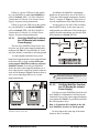
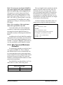
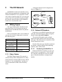
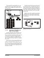
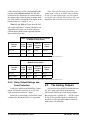
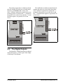
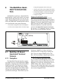
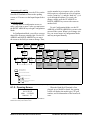
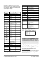
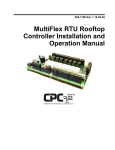
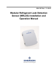
026-1704 Rev 4 07-25-03
MultiFlex I/O Board
Installation and
Operation Manual
1640 Airport Road, Suite 104
Kennesaw, GA 31044
Phone: (770) 425-2724
Fax: (770) 425-9319
ALL RIGHTS RESERVED.
The information contained in this manual has been carefully checked and is believed to be accurate. However, Computer Process Controls, Inc. assumes no responsibility for any inaccuracies that may be contained herein. In no event will
Computer Process Controls, Inc. be liable for any direct, indirect, special, incidental, or consequential damages resulting
from any defect or omission in this manual, even if advised of the possibility of such damages. In the interest of continued
product development, Computer Process Controls, Inc. reserves the right to make improvements to this manual, and the
products described herein, at any time without notice or obligation.
This product is covered under one or more of the following Computer Process Controls U.S. patents: 6360553,
6449968, 6378315, 6502409, 6578374, and Alsenz U.S. patents 4612776, 4628700, and 4535602.
READ ALL INSTRUCTIONS CAREFULLY
If the equipment is not used in the manner specified by the manufacturer, the protection provided
by the equipment may be impaired.
SAVE THIS INSTRUCTION MANUAL
This instruction manual contains important operating instructions for the MultiFlex family of I/O
boards, including the MultiFlex 16 input boards, and the MultiFlex 88, 88AO, 168, 168AO, and
168DO combination input/output boards.
Table of Contents
1 OVERVIEW OF THE MULTIFLEX PRODUCT LINE .......................................................................................... 1
1.1. MULTIFLEX 16 INPUT BOARD ......................................................................................................................................
1.2. MULTIFLEX COMBINATION INPUT/OUTPUT BOARDS...................................................................................................
1.3. OTHER BOARDS IN THE MULTIFLEX FAMILY ..............................................................................................................
1.3.1. The MultiFlex RTU ...............................................................................................................................................
1.3.2. The MultiFlex CUB-II and CUB-TD ....................................................................................................................
1
1
2
2
2
2 MOUNTING AND POWERING ................................................................................................................................. 3
2.1. SNAP-TRACK INSTALLATION ........................................................................................................................................
2.2. THE PLUG-IN OUTPUT BOARD .....................................................................................................................................
2.3. POWERING THE MULTIFLEX .........................................................................................................................................
2.3.1. Choosing Transformer Sizes .................................................................................................................................
2.3.2. MultiFlex 16 Power Wiring ..................................................................................................................................
2.3.3. MultiFlex Combination Input/Output Board Power Wiring.................................................................................
3
4
4
5
5
5
2.3.3.1. New-Style MultiFlex Combination I/O Boards (with Isolated Power Supply).................................................................. 6
2.3.3.2. Old-Style MultiFlex Combination I/O Boards (No Isolated Power Supply)...................................................................... 6
2.3.4. Wire Types and Maximum Distances.................................................................................................................... 7
3 THE I/O NETWORK .................................................................................................................................................... 8
3.1. WIRING TYPES .............................................................................................................................................................. 8
3.1.1. Daisy Chains ......................................................................................................................................................... 8
3.1.2. Network ID Numbers ............................................................................................................................................ 8
3.1.2.1. Numbering the MultiFlex 16 .............................................................................................................................................. 8
3.1.2.2. Numbering the MultiFlex 88, 88AO, 168, and 168AO ...................................................................................................... 9
3.1.2.3. Addressing the 168DO...................................................................................................................................................... 10
3.1.3. Setting the Baud Rate.......................................................................................................................................... 10
3.1.4. Setting the Terminating Resistance Jumpers ...................................................................................................... 10
4 I/O BOARD INPUT AND OUTPUT SETUP............................................................................................................ 11
4.1. THE INPUTS................................................................................................................................................................. 11
4.1.1. Connecting Sensors to Input Boards................................................................................................................... 11
4.1.1.1.
4.1.1.2.
4.1.1.3.
4.1.1.4.
4.1.1.5.
Wiring ...............................................................................................................................................................................
Input Wiring When Replacing 16AI or CIO/8IO Boards With MultiFlex.......................................................................
Sensor Wiring Types ........................................................................................................................................................
Input Type Dip Switches ..................................................................................................................................................
Pulse Type Inputs..............................................................................................................................................................
11
11
12
12
12
4.1.2. Power Connection............................................................................................................................................... 13
4.1.2.1. Current Ratings for On-Board Power Sources ................................................................................................................. 13
4.1.2.2. Powering Sensors Requiring 24VAC Off the Power Transformer................................................................................... 13
4.1.3. Sensor Types for MultiFlex Input Points ............................................................................................................
4.2. THE RELAY OUTPUTS .................................................................................................................................................
4.2.1. Output Fail-Safe Dip Switches............................................................................................................................
4.2.2. Relay Output Ratings and Fuse Protection.........................................................................................................
4.3. THE ANALOG OUTPUTS ..............................................................................................................................................
4.4. THE DIGITAL OUTPUTS ..............................................................................................................................................
13
13
13
14
14
15
5 BOARD STATUS LEDS ............................................................................................................................................. 16
5.1. STATUS LED .............................................................................................................................................................. 16
5.2. TX AND RX LEDS ...................................................................................................................................................... 16
5.3. CODE A AND CODE B LEDS ...................................................................................................................................... 16
Table of Contents • v
5.4. RELAY OUTPUT LEDS ................................................................................................................................................ 17
6 THE MULTIFLEX HAND-HELD TERMINAL INTERFACE ............................................................................. 18
6.1. MULTIFLEX I/O BOARD HAND-HELD TERMINAL SCREENS ....................................................................................... 18
6.1.1. Navigation ........................................................................................................................................................... 18
6.1.2. Opening Screen ................................................................................................................................................... 19
6.1.3. Board Address ..................................................................................................................................................... 20
6.1.4. Settings ............................................................................................................................................................... 20
6.1.5. Input/Output Select Menu.................................................................................................................................... 20
6.1.6. Input Screens ....................................................................................................................................................... 21
6.1.6.1.
6.1.6.2.
6.1.6.3.
6.1.6.4.
Input Status/Config Menu.................................................................................................................................................
Status-Volts.......................................................................................................................................................................
Status-Eng Units ...............................................................................................................................................................
Input Config ......................................................................................................................................................................
21
21
21
21
6.1.7. Relay Output Screens .......................................................................................................................................... 22
6.1.8. Analog Output Screens........................................................................................................................................ 23
6.1.8.1. Analog Status/Override..................................................................................................................................................... 23
6.1.9. Analog Fail-Safes................................................................................................................................................ 24
6.1.10. Digital Status (PWM) ....................................................................................................................................... 24
6.1.11. Digital Period Status......................................................................................................................................... 24
6.1.12. Config Fail % Screen ........................................................................................................................................ 25
vi • MultiFlex I/O Board I&O Manual
026-1704 Rev 4 07-25-03
1
Overview of the MultiFlex Product Line
Table 1-1 shows the part number of the MultiFlex 16.
P/N
The MultiFlex line of control system boards
provide a wide variety of input, output, and
smart control solutions, all of which are based on
a single universal hardware platform. The board
design uses flash-uploadable firmware and plugin expansion boards to configure the base platform board and apply it for use as an input
board, relay output board, analog output board,
or a combination I/O board.
1.1.
MultiFlex 16 Input Board
The MultiFlex 16 input board offers sixteen
combination analog/digital input points for use
by CPC Einstein and REFLECS control systems.
The MultiFlex 16 is designed to be 100% compatible with the previous generation of CPC
input boards (the 16AI), and may be used in retrofits with no additional hardware or software
setup or upgrades.
Like the 16AI, the MultiFlex 16 communicates with the site controller via an RS485 connection to a REFLECS COM A&D network or
an Einstein I/O network. Dip switches on the
board set the network ID (board number) and
baud rate.
The board also provides both +5VDC and
+12VDC output voltage points for use in powering transducers or other input devices that
require power.
Unlike the 16AI, the MultiFlex 16 has a
hand-held terminal interface, which may be used
by technicians to view the input voltage and
engineering unit values for each input point
without need of a voltmeter or front panel controller display.
MultiFlex 16 Input Board
810-3013
Model Name
MultiFlex 16
Description
16 analog/digital inputs, no outputs
Table 1-1 - MultiFlex 16 and 8 Input Board Models
1.2.
MultiFlex Combination
Input/Output Boards
There are several models of the MultiFlex
board that combine the functionalities of input
boards, relay output boards, digital output
boards, and analog output boards. The MultiFlex
combination input/output boards are designed to
be replacements for the 8IO Combination Input/
Output Board, but the MultiFlex board provides
several new hardware options and software features.
The MultiFlex combination I/O boards consist of two circuit boards: a bottom layer with up
to 16 combination digital/analog inputs, and a
plug-in top layer which contains a combination
of relay outputs, digital outputs, and analog outputs.
All boards feature both +5VDC and
+12VDC output voltage points for use in powering transducers or other input devices that
require power.
On the RS485 Network, the MultiFlex combination input/output boards present themselves
to the Einstein or REFLECS site controller as
16AI Analog Input Boards, 8RO Relay Output
Boards, 8DO Digital Output Boards, and/or
4AO Analog Output Boards, depending on what
type of inputs or outputs are equipped. Dip
switches are used to assign network ID numbers
to each board type.
Overview of the MultiFlex Product Line • 1
The MultiFlex combination input/output
boards also support a hand-held terminal interface, which allows technicians to view input values, check output states, and override output
points with fixed digital or analog values.
Table 1-2 shows the available models of
MultiFlex combination input/output boards.
P/N
Model Name
Description
810-3063
MultiFlex 88AO
8 analog/digital inputs, 8 relay outputs,
4 analog outputs
810-3064
MultiFlex 88
8 analog/digital inputs, 8 relay outputs
810-3065
MultiFlex 168AO
16 analog/digital inputs, 8 relay outputs,
4 analog outputs
810-3066
MultiFlex 168
16 analog/digital inputs, 8 relay outputs.
810-3067
MultiFlex 168DO
16 analog/digital inputs, 8 relay outputs,
and 4 pulse-width
modulating digital
outputs
Table 1-2 - MultiFlex Combination Input/Output Board Models
1.3.
Other Boards in the MultiFlex Family
In addition to the I/O boards described
above, the MultiFlex hardware is used as the
base for a number of “smart” boards capable of
controlling refrigeration and HVAC systems or
subsystems independently from a central site
controller. These boards are considered “controllers” in their own right, and are therefore covered in separate manuals. For informational
purposes, these boards are described below.
1.3.1. The MultiFlex RTU
Similar in design to the MultiFlex combination input/output boards, the MultiFlex RTU
board is designed specifically for operating
package rooftop HVAC units as part of an Einstein BX or REFLECS BCU building control
2 • MultiFlex I/O Board Operator’s Guide
system. The MultiFlex RTU is designed to be a
replacement for the previous generation ARTC,
and is 100% compatible with all legacy Einstein
BX and BCU systems.
The MultiFlex RTU board has 16 analog
inputs, 8 relay outputs and 4 analog outputs.
Most of these I/O points are reserved for sensors
and input devices required to read environmental
data (such as space and supply air temperature)
and control all output devices that control the
environment (such as heat/cool stages and
dampers). The RTU relay outputs are rated for
line voltage (240VAC).
The RTU board controls the rooftop unit
directly with its built-in heating, cooling, and
humidity control algorithms. It may operate in
stand-alone mode, or it may interface with an
Einstein BX or BCU to control the store environment in zones and pass along logging and
alarm information.
The MultiFlex RTU has its own installation
and operation manual, P/N 026-1706.
1.3.2. The MultiFlex CUB-II and
CUB-TD
The MultiFlex Condensing Unit Board
(CUB) is a “smart” input/output board designed
to control single condensing units. The MultiFlex CUB-II controls all aspects of a condensing
unit, including compressor control, and condenser fan control. The MultiFlex CUB-TD is a
scaled-down version of the CUB-II that controls
condenser fans using a temperature differential
strategy.
The MultiFlex CUB uses the same general
hardware configuration as a MultiFlex 168AO.
It is equipped with a processor and extra memory to allow it to control compressors, condensers, refrigeration, and defrost for a single
condensing unit using on-board I/O and control
algorithms.
The MultiFlex CUB has its own installation
and operation manual, P/N 026-1705.
026-1704 Rev 4 07-25-03
2
Mounting and Powering
The MultiFlex boards are usually installed
by the refrigeration or building equipment manufacturer. Therefore, the installer need only
make the necessary connections between the
boards and the site controller(s).
2.1.
Snap-Track Installation
MultiFlex boards not supplied in a custom
panel or other enclosure are supplied with a
snap-track for easy installation. The insulation
sheet and I/O board must be removed from the
track before the track is mounted. The snap-track
is mounted using the 0.1875” mounting slots.
Figure 2-1 shows this installation procedure.
In some instances, an installer may be
required to mount an I/O board. There are no
restrictions on the location of these boards; however, for ease of network configuration, it is recommended that the boards be located adjacent to
the Einstein. I/O boards may be mounted without an enclosure, but they should be mounted in
a location that is not easily accessible to avoid
tampering or damage.
Figure 2-1 - MultiFlex Snap-Track Mounting
Figure 2-2 provides mounting dimensions
for the MultiFlex board.
Figure 2-2 - MultiFlex Board Dimensions
Snap-Track Installation
Mounting and Powering • 3
2.2.
The additional board makes the MultiFlex
combination I/O boards considerably taller than
the MultiFlex 16 and all previous-generation
CPC I/O boards. If you will be mounting these
boards in an enclosure, the board will need at
least 2.5" of clearance between the base board
and the panel door.
The Plug-In Output
Board
2.3.
Powering the MultiFlex
All models of MultiFlex require a 24VAC
Class 2 input power source. The MultiFlex 16
requires the power source to be center-tapped.
All other models do not use the center tap.
CPC supplies a wide variety of 24VAC
transformers with varying sizes and either with
or without center taps. Table 2-1 shows the
transformer sizes and whether they are centertapped or non-center-tapped.
Figure 2-3 - Exploded View -- MultiFlex Combination I/O Board
All MultiFlex boards except the MultiFlex
16 have output sub-boards that plug in to the top
of the base board. These boards are shipped with
the output board pre-installed on the board using
stand-offs, so no additional hardware setup
should be necessary.
Xformer P/N
VA Rating
Primary Voltage
Center Tap?
640-0041
50 VA
110 VAC
No
640-0042
50 VA
220 VAC
No
640-0056
56 VA
Multi-tap (120/208/240 VAC)
Yes
640-0050
75 VA
110 VAC
No
640-0045
75 VA
220 VAC
No
640-0080
80 VA
Multi-tap (120/208/240 VAC)
Yes
Table 2-1 - Transformers Compatible with MultiFlex Board
4 • MultiFlex I/O Board Operator’s Guide
026-1704 Rev 4 07-25-03
2.3.1. Choosing Transformer Sizes
In most site installations, a single transformer will power multiple devices. Choose a
transformer with a VA rating large enough to
power all devices that will be attached to it.
Table 2-2 gives the VA ratings of the MultiFlex
board products. Refer to your site controller’s
manual for VA ratings of the other I/O boards
that may be powered by one of these transformers.
Unit
VA
VAC
Center
tapped?
MultiFlex 16
6
24
Yes
MultiFlex 88,
88AO, 168,
168AO and
168DO
15
24
NO
Table 2-2 - Device Power Requirements
2.3.2. MultiFlex 16 Power Wiring
The MultiFlex 16 requires connection to a
transformer with a center tap such as the 56VA
(640-0056) and 80VA (640-0080) transformers
listed in Table 2-1. The 56VA and 80VA transformers have quick-connects on the primary and
secondary sides for connection to line voltage
and the MultiFlex 16 board. Figure 2-4 shows
how to make those connections. Note the center
tap connection on the secondary side (CT) must
be wired to the 0V terminal on the MultiFlex 16.
2.3.3. MultiFlex Combination Input/
Output Board Power Wiring
The MultiFlex 88, 88AO, 168, 168AO, and
168DO boards do not use a center tap. Instead,
the 0V terminal on the board should be connected to a separate Earth ground.
Important! The rules that must be followed when connecting a MultiFlex Combination I/O board to a transformer are
different depending on whether you have a
"new style" MultiFlex board with an isolated
power supply (all MultiFlex boards shipped
after November 1, 2002) or an "old style"
MultiFlex board (all MultiFlex boards
shipped before November 1, 2002).
A new-style MultiFlex Combination I/O
board has a green power LED located next to the
24VAC connection terminal in the upper right
corner of the circuit board (see Figure 2-5 for
reference).
24 VAC
POWER LED
New Style
MultiFlex Board
(Top Left Corner)
24 VAC
NO POWER LED
Old Style
MultiFlex Board
(Top Left Corner)
Figure 2-5 - New-Style vs. Old-Style MultiFlex Board
Figure 2-4 - 640-0056 and 640-0080 Transformer Wiring
Powering the MultiFlex
Mounting and Powering • 5
If there is a power LED next to the connector, your MultiFlex is a new-style MultiFlex -refer to Section 2.3.3.1., New-Style MultiFlex
Combination I/O Boards (with Isolated Power
Supply) for power wiring instructions.
In addition, the MultiFlex combination
boards can be powered by one of the 50VA or
75VA non-center-tapped transformers listed in
Table 2-1 on page 4. Figure 2-7 shows how to
wire the transformers to the MultiFlex boards.
If there is no power LED next to the connector, your MultiFlex is an old-style MultiFlex -refer to Section 2.3.3.2., Old-Style MultiFlex
Combination I/O Boards (No Isolated Power
Supply) for power wiring instructions.
You may also tie one side of the secondary
(but not BOTH sides) or the center tap to an
earth ground, provided none of the boards powered by the same transformer are old-style MultiFlex boards (see Section 2.3.3.2.).
2.3.3.1.
New-Style MultiFlex Combination I/O Boards (with Isolated
Power Supply)
The new-style MultiFlex board can be connected to any of the center-tapped transformers
mentioned in Table 2-2, provided the 0V terminal of the board is connected to an Earth ground.
A center-tapped transformer may power
both center-tapped and non-center-tapped boards
at the same time, as long as none of the noncenter-tapped MultiFlex boards are old-style
MultiFlex boards. If an old-style MultiFlex
shares the same center-tapped transformer as a
device that uses the center tap, boards on the network will be damaged. Figure 2-6 shows how to
wire a non-center tapped device to a centertapped transformer.
Figure 2-7 - Non-Center-Tapped Transformer Wiring
All wire connections to earth ground should
be less than six (6) inches long and use a wire
gauge of at least 14AWG.
2.3.3.2.
Old-Style MultiFlex Combination I/O Boards (No Isolated
Power Supply)
Like the new-style MultiFlex board, the oldstyle MultiFlex Combination I/O board can be
connected to any of the center-tapped transformers mentioned in Table 2-2, provided you follow
the following three rules:
Rule 1: Ground the 0V terminal on the oldstyle MultiFlex board to an Earth ground.
Figure 2-6 - Wiring Non-Center Tapped MultiFlex Boards to
Transformers With a Center Tap
6 • MultiFlex I/O Board Operator’s Guide
Do not connect the center tap of the transformer to the 0V terminal.
026-1704 Rev 4 07-25-03
Rule 2: Do not power an old-style MultiFlex
non-center-tapped board with a transformer
that is also powering a center-tapped device.
This means you cannot connect an old-style
MultiFlex non-center tapped board to a transformer that is powering a MultiFlex 16, 16AI,
8RO, 4AO, 8DO, a Gateway board, or any previous generation CPC board that uses centertapped power. Doing so will destroy the MultiFlex board.
Rule 3: The secondary of the transformer
must not be grounded on any side.
Verify that neither side of the transformer
secondary is connected to earth ground before
powering the old-style MultiFlex board. A
grounded secondary will damage the MultiFlex
board.
In addition, the old-style MultiFlex combination boards can be powered by one of the 50VA
or 75VA non-center-tapped transformers listed
in Table 2-1 on page 4. Figure 2-7 shows how to
wire the transformers to the MultiFlex boards.
The wire length from the transformer and the
number of boards connected to the same wire
determines the type wire gauge used. In most
cases, the distance between the I/O boards and
the transformer that supplies power to them is
not enough to be concerned with. But it is very
important not exceed this maximum wire length
or the boards will malfunction.
Use these formulas to determine if the wire
gauge you are using fits within specification:
14 AWG:
Feet = 0.40/(VA/24) x 0.005
18 AWG:
Feet = 0.40/(VA/24) x 0.013
(VA is the total VA rating of the I/O boards)
For example, if you had an 80 VA load:
14 AWG: 24 ft. (rounded down)
18 AWG: 9 ft.
Figure 2-8 - Power Wire Lengths
2.3.4. Wire Types and Maximum
Distances
For powering I/O boards, use only the listed
wire types from Table 2-3. Three-conductor
non-shielded cables are the recommended wire
for connecting between the center tapped transformer and the I/O boards. Shielded cable should
not be used for power wiring. The center tap
should be wired with the third conductor to earth
ground at the transformer.
Each MultiFlex board should have its 0V terminal taken to a short, solid earth ground.
Power Wiring Types
14 AWG
Belden 9495 or equivalent
18 AWG
Belden 9493 or equivalent
Table 2-3 - Power Wiring Types
Powering the MultiFlex
Mounting and Powering • 7
3
The I/O Network
A diagram of this network arrangement is
shown in Figure 3-1.
All MultiFlex boards and controllers use an
RS485 network connection to communicate with
Einstein and REFLECS site controllers. Technicians who are familiar with CPC’s previous generation 16AI, 8IO, and ARTC boards will find
the network setup procedure for the MultiFlex
boards to be very much the same.
3.1.
TERMINATION
TERMINATION
Wiring Types
CPC specs Belden #8641 shielded twisted
pair cables for use as I/O network wiring (or
Belden #82641 and Belden #88641 for plenum
installations).
If the recommended cable is not available in
your area, be sure the wiring meets or exceeds
the following specs:
Shielded?
Yes
Conductor Type
Twisted Pair
Gauge
18 - 24 AWG
Capacitance between
signal wires
31 pF/ft or less
Capacitance between
signal and shield
59 pF/ft or less
Nominal Impedance
120Ω±50Ω
Table 3-1 - RS485 I/O Network Wiring Specifications
3.1.1. Daisy Chains
The RS485 Input/Output (I/O) network is
wired in a daisy-chain configuration. In a daisy
chain, boards are wired together in series with no
branches or "star configurations," and the network is terminated at either end of the daisychain.
8 • MultiFlex I/O Board Operator’s Guide
Figure 3-1 - I/O Network Configurations
3.1.2. Network ID Numbers
Each device on an RS485 segment has a network dip switch that must be used to assign the
board a unique network ID number.
The network ID number makes a board
unique from other boards on the network of the
same type. This allows the site controller to find
it and communicate with it.
Boards of the same type should be numbered
in sequence, starting with one and continuing
with two, three, and so forth.
3.1.2.1.
Numbering the MultiFlex 16
Both the MultiFlex16 and the previous-generation 16AI are recognized as “16AIs” by the
site controller, and therefore each one of both
types of boards should have a unique board
number.
026-1704 Rev 4 07-25-03
The network ID on the MultiFlex 16 is set
using the first five dip switches on dip switch
bank S3. Refer to Figure 3-2 for dip switch setting instructions.
The 88AO and 168AO also must be treated
as an 8RO and 16AI, except that since there are
analog outputs on these models, the analog outputs must be treated as a separate 4AO board. In
other words, each 88AO and 168AO is in effect
three different I/O boards: one 16AI, one 8RO,
and one 4AO.
Figure 3-3 provides a graphic representation
of input and relay output board numbering for
two MultiFlex 16s, three 8ROs, and two MultiFlex 88 boards.
Figure 3-2 - 16 Network ID and Baud Rate Switches
3.1.2.2.
Numbering the MultiFlex 88,
88AO, 168, and 168AO
Figure 3-3 - Network Device Numbering (Example Shows
REFLECS COM A & COM D)
Network numbering for the MultiFlex combination input/output boards are a special case.
They are actually a combination of three types of
CPC boards: the inputs are configured like a
16AI, the relay outputs are configured like an
8RO, and the four analog outputs are configured
like a 4AO.
When an 88 or 168 is present on the network,
it must be treated like both an 8RO and a 16AI
board type. Therefore, when numbering 88s and
168s, you must number the input portion of the
board as a 16AI, and the relay output portion of
the board as an 8RO.
Wiring Types
The I/O Network • 9
The board numbering dip switches on the
MultiFlex 88, 88AO, 168, and 168AO are S3
and S4, as shown in Figure 3-4. Switches 1-5 on
S3 set the input (16AI) network address.
Switches 1-5 on S4 set the relay output (8RO)
address, and switches 6-8 on S4 set the analog
output (4AO) address.
baud. Either may be used -- refer to your site
controller’s user manual for the baud rate recommendation (currently 9600 baud for both
REFLECS and Einstein controllers).
On all MultiFlex boards, switches 6 and 7 on
S3 are used to set the baud rate. To communicate
at 9600 baud, set switch #6 UP and #7 DOWN.
For 19200 baud, set switch #6 DOWN and #7
UP. Refer to Figure 3-2 and Figure 3-4 for a
visual look at how the switches must be set.
3.1.4. Setting the Terminating Resistance Jumpers
All MultiFlex boards and other RS485
devices have a set of terminating resistance
jumpers (one jumper for each wire lead). These
jumpers are labeled JP2, JP3, and JP4 on the
MultiFlex board.
Figure 3-4 - 168AO Network ID and Baud Rate Switches
3.1.2.3.
The purpose of the jumpers is to indicate the
two ends, or termination points, of the segment.
On a daisy chain, one device at the beginning
and one device on the end must be terminated.
On the MultiFlex, this is done by placing all
three termination jumpers in the OUT (toward
the left edge of the board) position. To unterminate a MultiFlex, these jumpers must be set to
the IN (toward the center of the board) position.
Figure 3-5 shows the termination jumper settings for all MultiFlex boards.
Addressing the 168DO
Setting up the network ID numbers for the
168DO is the same as setting up a 168AO (see
Section 3.1.2.2.), except switches 6-8 on switch
bank S4 set the virtual 8DO board address
instead of the 4AO address as shown.
3.1.3. Setting the Baud Rate
All I/O boards have dip switches that determine the baud rate at which they communicate.
Currently, the baud rate dip switch in network
components may be set at either 9600 or 19200
Figure 3-5 - I/O Network Termination Jumper Settings
10 • MultiFlex I/O Board Operator’s Guide
026-1704 Rev 4 07-25-03
4
4.1.
I/O Board Input and
Output Setup
The Inputs
The inputs on a MultiFlex board are compatible with a wide range of analog and digital sensors and transducers. In general, the inputs are
capable of reading analog voltage signals in the
range of 0V to +7VDC and dry-contact (no outside voltage) digital sensors and switches.
The specific types of input devices that must
be used with MultiFlex is largely dependent on
the site controller MultiFlex is connected to;
refer to the site controller’s user’s manual for a
full list of compatible sensors and specific sensor wiring instructions.
4.1.1. Connecting Sensors to Input
Boards
Wiring a sensor to the input points on a MultiFlex board requires three steps:
1. Connect the sensor’s signal wires to the two
terminals of an input point.
2. Set the input type dip switch that corresponds to the point being connected.
3. If necessary, connect the sensor to one of the
5V or 12V power terminals.
The Inputs
4.1.1.1.
Wiring
An input point on a MultiFlex board consists
of two terminals, as shown in Figure 4-1. One of
these terminals, labeled “SIG,” reads the signal
from the sensor, while the other, labeled “0v” is
where the sensor’s ground and/or cable shield
wire is connected.
Figure 4-1 - Input Board Points
4.1.1.2.
Input Wiring When Replacing
16AI or CIO/8IO Boards With
MultiFlex
If the MultiFlex you are installing is replacing an existing 16AI, CIO, or 8IO, you will not
be able to simply unplug the input connectors
from the old board and plug them into the MultiFlex. Doing so will cause the inputs to be
reversed and the polarity to be swapped for
points 1 through 8.
You must either re-wire points 1 through 8 to
the proper place on the MultiFlex board, or
obtain Multiflex input adapter cables (P/N 3352301), as shown in Figure 4-2. For each 8-terminal connector plugged into points 1-4 and 5-8,
I/O Board Input and Output Setup • 11
unplug the connector from the old board and
plug it into the female end of the adapter. Plug
the male end into the appropriate MultiFlex
input socket.
MALE END (PLUG INTO
MULTIFLEX
INPUT SOCKET)
FEMALE END (PLUG INPUT
CONNECTOR FROM OLD
BOARD HERE)
RIBBON CABLE
(P/N 335-2301)
POINT #4
POINT #4
POINT #3
POINT #3
POINT #2
POINT #2
POINT #1
POINT #1
Figure 4-2 - MultiFlex Input Adapter Cable
The connectors for points 9-12 and 13-16 on
the old board are already correctly oriented, and
may be plugged directly into the new MultiFlex
without an adapter cable.
4.1.1.3.
The input type dip switch tells the input
board whether or not the sensor connected to the
point is a resistive type sensor. Generally, if the
sensor or transducer supplies its own voltage
signal to the point, the dip switch should be set
to the LEFT (OFF) position. If the sensor uses
variable resistance and requires voltage to be
supplied to it from the input point, set the dip
switch to the RIGHT (ON) position. Dip
switches for unused points should be set to the
RIGHT (ON) position.
The exception to this rule is for CPC’s
5VDC pressure transducers -- though they
supply their own voltage signal, the dip switch
MUST be set to the RIGHT (ON) position.
Sensor Wiring Types
Specific wiring types are required for each
type of sensor used with Einstein or RMCC.
All Analog Temperature Sensors and Air Flow Sensors
Temperature and air flow sensors are to be
wired with shielded, 2 conductor, at least 22 GA
wire (Belden # 8761 or equivalent).
All Pressure Transducers, Humidity Sensors, and Refrigeration Transducers
Pressure and refrigeration transducers and
humidity sensors are to be wired with shielded, 3
conductor, at least 22 GA wire (Belden #8771 or
equivalent).
Dew Point and Light Level Sensors
These sensors are to be wired with shielded,
4 conductor at least 22 GA wire (Belden # 8729
or equivalent).
4.1.1.4.
Input Type Dip Switches
Each MultiFlex input point has an input type
dip switch that must be set. Input type dip
switches are located in the switch banks labeled
S1 and S2.
12 • MultiFlex I/O Board Operator’s Guide
Figure 4-3 - Input Type Dip Switches for 16 Board
4.1.1.5.
Pulse Type Inputs
The MultiFlex supports pulse accumulation
inputs such as the kind supplied by some power
transducers. Pulse accumulation inputs pulse a
voltage at a certain rate that corresponds to a value.
If your site controller is an Einstein or a REFLECS BCU version 2.0 or above, you may connect pulse accumulation inputs to any point on
the board.
If you have a REFLECS BCU with a version
number below 2.0, an RMCC (any version) or a
BEC (any version), you may only connect a pulse
accumulation input to a single input on the MultiFlex board.
026-1704 Rev 4 07-25-03
1. Connect the input to the point labeled
INPUT #1. This is the only point on the
board that may accept this type of input.
2. Locate switch #8 on the dip switch bank
labeled S3 (the same one that sets input
board network ID). Set switch #8 to the UP
(ON) position. This will tell the REFLECS
that the input on point #1 is a pulse accumulation input.
4.1.2. Power Connection
If power is needed to operate the sensor, four
points are provided on the MultiFlex board that
supply DC power: one +12VDC point, and three
+5VDC points. See Figure 4-4 for the location
of these points.
This can only be done with sensors that keep
the 24VAC signal isolated from its DC output
signal (such as CPC’s Dew Point Probe). If the
output signal is not isolated from the 24VAC
input, you must use a separate transformer.
4.1.3. Sensor Types for MultiFlex
Input Points
Because different controllers may be compatible with different sensor types, this manual
cannot list all sensor types and how to wire them
to a MultiFlex input point. Refer to your site
controller’s documentation for sensor wiring
information.
4.2.
The Relay Outputs
The MultiFlex Combination I/O boards have
Form C relay contacts. Figure 4-5 shows how to
wire the three-terminal Form C contact.
Figure 4-4 - Input Board Power Sources
4.1.2.1.
Current Ratings for On-Board
Power Sources
The maximum current that may be drawn
from the +12VDC terminal is 100 milliamps.
The maximum current that can be drawn from
all three +5VDC terminals COMBINED is 50
milliamps.
4.1.2.2.
Powering Sensors Requiring
24VAC Off the Power Transformer
Some sensors that requires 24VAC can be
powered off the MultiFlex’s own 24VAC power
connection. To connect to the 24VAC power
source, connect the sensor’s power wires to terminals AC1 and AC2.
The Relay Outputs
One wire of the two-wire connection should
always be connected to the middle terminal. The
second wire must either be connected to the N.C.
terminal (if you want the path to be closed when
the relay is de-energized) or the N.O. terminal (if
you want the path to be open during power failure).
The contacts you choose also affect what the
board’s fail-safe dip switch will need to be set to
for proper operation. Refer to Table 4-1 and
Table 4-2 on page 14.
RELAY IS
CLOSED
ON POWER
FAILURE
N.C.
N.O.
RELAY IS
OPEN ON
POWER
FAILURE
N.C.
N.O.
Figure 4-5 - Form C Contact Wiring
4.2.1. Output Fail-Safe Dip Switches
When a controller calls for a MultiFlex relay
output to be ON, it sends a command to the MultiFlex to turn the output to the ON state (signified by the output LED being ON). The behavior
I/O Board Input and Output Setup • 13
of the relay when it is ON is determined by the
position of the fail-safe switch. The fail-safe
switches for the outputs are on a switch bank at
the bottom right corner the plug-in output module. Each switch corresponds to an output on the
board (switch #1 = output #1, etc.).
Note: There are not many cases where you
would want a relay to be OPEN when called to
be ON. For most applications, you will want to
set the fail-safe switch to UP so that an ON command from the controller will close the relay.
Table 4-1 and Table 4-2 show how the failsafe switch and Form C contacts should be configured based on how you want the output to
perform during both normal operation and during network/power loss.
State of Normally Closed (N.C.) Contacts
on MultiFlex Relay Points
Fail-safe
Switch
Light
is ON
Light
is OFF
Loss of
Communi
cation
Loss of
Power
Up (ON)
Closed
Open
Closed
Closed
Down (OFF)
Open
Closed
Closed
Closed
Table 4-1 - Output Board Fail-Safe and Switch Settings when Contact is Wired Normally Closed (N.C.)
State of Normally Open (N.O.) Contacts on
MultiFlex Relay Points
Fail-safe
Switch
Light
is ON
Light
is OFF
Loss of
Communi
cation
Loss of
Power
Up (ON)
Open
Closed
Open
Open
Down (OFF)
Closed
Open
Open
Open
Table 4-2 - Output Board Fail-Safe and Switch Settings when Contact is Wired Normally Closed (N.O.)
4.2.2. Relay Output Ratings and
Fuse Protection
Each relay output on the MultiFlex Combination I/O boards is rated for up to 240 VAC
with a maximum current of 2 amps.
Each relay is fused with a 2A fast-blow 5mm
x 20mm fuse, Bussman GMA-2 or equivalent.
14 • MultiFlex I/O Board Operator’s Guide
4.3.
The Analog Outputs
All varieties of the MultiFlex board that have
an “AO” at the end of their model number
(88AO and 168AO) have four analog outputs
that can provide a variable 0V - +10VDC signal
to any of four variable-speed or variable-position devices. The maximum output current for
each point is 10 milliamps.
026-1704 Rev 4 07-25-03
The 168DO has no hardware-based fail-safe
settings (fail-safes are set up in the board firmware). All that is required is to connect the “+”
terminal to the positive wire on the device and
the “-” terminal to the negative (or ground) wire
of the device.
DIGITAL
The analog outputs have no hardware-based
fail-safe settings (fail-safes are set in the board
firmware; see Section 6.1.9., Analog FailSafes). All that is required to connect a device to
an analog point is to connect the “+” terminal to
the positive wire on the device and the “-” terminal to the negative (or ground) wire of the
device.
Figure 4-7 - MultiFlex Digital Points
Figure 4-6 - MultiFlex Analog Points
4.4.
The Digital Outputs
The MultiFlex 168DO board has four digital
outputs that pulse a +8VDC signal. Each output
is rated up to 10 milliamps.
The Digital Outputs
I/O Board Input and Output Setup • 15
5
Board Status LEDs
When a MultiFlex board is powered up, you
will be able to determine the operating status of
the board by observing its status LEDs. Figure
5-1 shows the location of the MultiFlex’s status
LEDs.
Figure 5-1 - MultiFlex Status LED Locations
5.1.
Status LED
The Status LED simply blinks GREEN once
per second to show that the board is powered
and operational. If this light is dark, the board
has likely lost power.
5.2.
Tx and Rx LEDs
The Tx and Rx LEDs indicate when the MultiFlex is sending or receiving messages on the
RS485 network.
The Tx LED blinks once every time the MultiFlex sends a response to the Einstein or
REFLECS. The Rx LED blinks once when the
MultiFlex receives a message.
If the MultiFlex is connected to the network
and set up to communicate with the controller,
you should see these lights blinking regularly. If
they do not, there may be a problem with the network.
5.3.
Code A and Code B LEDs
All MultiFlex I/O boards except the MultiFlex 16 have two LEDs labeled Code A and
Code B. These LEDs indicate failure conditions.
When these LEDs are OFF, there are no failures
active. When one or both of these LEDs are
blinking, there are failure conditions. The rate of
blinking indicates the type of failure:
Code A Failure Conditions
• Blinking fast (4 times/second) - There is a problem
with the flash memory or hardware clock on this
board. This generally means the board is bad and
must be replaced.
• Blinking slow (1 time/second) - The board is not receiving any messages addressed to it. This means ei-
16 • MultiFlex I/O Board Operator’s Guide
026-1704 Rev 4 07-25-03
ther the I/O network is down or it has not yet been
commissioned in the Einstein or REFLECS Network Configuration screen.
Code B Failure Conditions
• Blinking 2 times/second - This indicates the board
has lost its configuration. For the MultiFlex I/O
boards, a board is considered “configured” if you
have specified input type settings and analog output
fail-safes. If Code B blinks at this rate on an operational board, it means the board must be reprogrammed.
This light does not blink if the board is new or is using the unmodified default configuration.
5.4.
Relay Output LEDs
Each relay output point on a MultiFlex has
an indicator LED that shows the status of the
output. This LED is lit to show the output is ON,
and unlit to show the output is OFF.
The definition of ON and OFF in this case is
determined by the position of the fail-safe dip
switch (see Table 4-1 and Table 4-2).
Relay Output LEDs
Board Status LEDs • 17
6
The MultiFlex HandHeld Terminal Interface
All MultiFlex boards have a Hand-Held Terminal interface, which can be used to view status
for the board without having to use the site controller. Though different for each model of MultiFlex, the Hand-Held Terminal interface allows
you to perform the same general functions:
• View failure messages that relate to the MultiFlex
• View the status of inputs (both in volts and in engi-
neering units appropriate to the sensor type)
• View the current state of relay outputs (ON or OFF)
and analog outputs (both in volts and in percentage)
• Override relay outputs to a fixed ON or OFF state,
or override analog outputs to a fixed percentage
• Configure set points
Plugging In the Hand-Held Terminal
The Hand-Held Terminal plugs into the
RJ11 jack on the MultiFlex base board (located
on the bottom left side of the board, as shown in
Figure 6-1). Press the Hand-Held Terminal connector into the jack until it snaps into place.
When the connector is correctly seated, the
screen to the Hand-Held Terminal will display
the message “CPC Handheld Terminal” and then
the first screen of the MultiFlex interface.
Figure 6-1 - MultiFlex HHT Jack Location
6.1.
MultiFlex I/O Board
Hand-Held Terminal
Screens
6.1.1. Navigation
The Hand-Held Terminal interface consists
of a simple series of screens and menus. Figure
6-2 shows a complete map of all screens for the
MultiFlex board(s). The options for working
with inputs, relay outputs, and analog outputs
stem from an Input/Output Select Menu, which
will give you only the options appropriate for
your board’s model type. This means if you are
18 • MultiFlex I/O Board Operator’s Guide
looking at a MultiFlex 16, there will be no
options listed for viewing relay or analog outputs. If you are using a MultiFlex 88 or 168,
there will be no analog or digital output options.
Scrolling Through The Hand-Held Screens
The UP ARROW and DOWN ARROW
keys are used to scroll through the screens. Some
of these screens, shown as dotted-line boxes in
Figure 6-2, are read-only, meaning there are no
editable fields; others, shown as solid-line
boxes, are either menus that require you to enter
a selection or are configuration screens that have
one or more changeable fields.
026-1704 Rev 4 07-25-03
use the number keys to enter a value, or if the
field requires a selection from a list of options,
use the “point key” (.) and the “dash key” (-) to
cycle through the options. To record your
change, simply press the UP ARROW or
DOWN ARROW key to move the cursor to
another field.
Shortcut Keys (F1 and F2)
At any time, you may press the F1 key on the
Hand-Held Terminal to return to the opening
screen, or F2 to move to the Input/Output Select
menu.
Configuration Mode
On any menu or configuration screen, to
make a selection or enter a value you must press
the RIGHT ARROW key to begin Configuration
Mode.
To exit Configuration Mode, use the UP
ARROW or DOWN ARROW keys to move the
cursor off the screen. When it is no longer visible, you are no longer in Configuration Mode
and may navigate normally.
In Configuration Mode, you will see a cursor
shaped like an arrow pointing right. Use the UP
ARROW and DOWN ARROW keys to move
the cursor to the field you want to change. Then,
F1
F2
OPENING
SCREEN
BOARD
ADDRESS
SETTINGS
1
2
INPUT
STATUS/
CONFIG
1
2
STATUS
(VOLTS)
INPUT/
OUTPUT
SELECT
MENU
3
RELAY
STATUS/
OVRD 1-4
3
STATUS
(ENG. UNITS)
1
SELECT
ENG.
UNITS
OTHER SCREENS (4 INPUTS per SCREEN)
=
READ-ONLY SCREENS
(NO EDITABLE FIELDS)
=
MENU or CONFIGURATION SCREEN
3
ANALOG
STATUS
MENU
RELAY
STATUS/
OVRD 5-8
DIGITAL
STATUS
MENU
2
ANALOG
STATUS/OVR
(VOLTS)
ONLY AVAILABLE
ON BOARDS WITH
RELAY OUTPUTS
(168, 168AO,
88, 88AO,
168DO)
1
ANALOG
FAIL-SAFES
ONLY AVAILABLE
ON BOARDS WITH
ANALOG OUTPUTS
(168AO, 88AO)
2
DIGITAL
STATUS PWM %
3
- PERIOD
(SECONDS)
CONFIG
FAIL %
ONLY AVAILABLE
ON BOARDS WITH
DIGITAL OUTPUTS
(168DO)
TO ENTER CONFIGURATION MODE
AND
TO SELECT FIELD
AND
TO SELECT FIELD VALUES (OR USE
NUMBER KEYS)
Figure 6-2 - MultiFlex I/O Board Hand-Held Terminal Interface Navigation Map
6.1.2. Opening Screen
MULTIFLEX 16
810-3013
VER: 1.00F01
(PRESS ↓)
When the Hand-Held Terminal is first
plugged in to a MultiFlex board, the opening
screen will display the model type, CPC part
number, and version number of the board software.
NOTE: At any time, pressing F1 on the Hand-Held Terminal will return you to this screen.
MultiFlex I/O Board Hand-Held Terminal Screens
The MultiFlex Hand-Held Terminal Interface • 19
The last line of the display will also show if
any failure conditions are active. If there are failure conditions, the last line will display the message “FAIL:” followed by a description of the
condition. If there is no failure condition, the last
line of the display will prompt the user to press
the DOWN ARROW key to continue.
6.1.3. Board Address
168AO Screen
Board Address:
16AI: 1
8RO: 1
4AO: 1
168DO Screen
Board Address:
16AI: 1
8RO : 1
8DO : 1
The Board Address screen shows the current
board address settings for the MultiFlex. The
numbers shown here are read directly from the
network address dip switch settings on the
board. This screen does NOT allow you to
change the board numbers with the Hand-Held
Terminal; this must be done by setting the network address dip switches. Refer to Section
3.1.2., Network ID Numbers, for dip switch setting information.
The MultiFlex will not display address numbers that do not pertain to the model type. In
other words, a MultiFlex 16 will not show fields
with the 8RO and 4AO address numbers, and an
88 or 168 will not show a field for the 4AO
address number.
If an 16AI, 8RO, or 4AO field that is supposed to appear on this screen is not shown, it is
because the board number dip switches for these
board types are set to “0.” Set the 8RO and 4AO
dip switch settings to a unique number (refer to
Section 3.1.2.2., Numbering the MultiFlex 88,
88AO, 168, and 168AO). The Hand-Held Terminal should update within a few seconds and
show the 8RO and 4AO board numbers.
20 • MultiFlex I/O Board Operator’s Guide
6.1.4. Settings
Settings:
Baud: 9600
In 1 Pulse? NO
This screen shows the baud rate dip switch
setting for the board, and the position of S3
switch #8, which is required to be UP for all
RMCC (all versions), BEC (all versions), and
BCU (versions below 2.0) units if pulse accumulation inputs are being used. This screen does
NOT allow you to change the baud rate or pulse
settings with the Hand-Held Terminal; this must
be done by setting the dip switches. Refer to
Section 3.1.3., Setting the Baud Rate and Section 4.1.1., Connecting Sensors to Input Boards
for more information about these dip switch settings.
6.1.5. Input/Output Select Menu
168AO Screen
SELECT: 1
1= Inputs
2= 8 Relay Outs
3= 4 Analog Outs
168DO Screen
SELECT: 1
1= Inputs
2= 8 Relay Outs
3= 4 DO PWM Outs
This menu is where you select whether you
want to view the board’s inputs, relay outputs, or
analog outputs. To select, press the RIGHT
ARROW key to make the cursor appear, and
then enter either 1 (for inputs), 2 (for relay outputs), or 3 (for analog outputs on the 4AO, or
digital outputs on the 8DO). Then, press the
DOWN ARROW key once to exit Configuration
Mode and DOWN ARROW again to access the
first status screen for the selection you made.
026-1704 Rev 4 07-25-03
6.1.6. Input Screens
6.1.6.1.
6.1.6.3.
Input Status/Config Menu
SELECT: 1
1= STATUS-VOLTS
2= STATUS-ENG UN
3= INPUT CONFIG
The Input Status/Config Menu offers three
choices:
1.
STATUS-VOLTS - Selecting this option will
show the status of all the inputs in volts.
2.
STATUS-ENG UN - Selecting this option
will show the status of all the inputs in engineering units. Engineering units must be
specified for each input using the Input Config screens (option 3), or else the board assumes the input is a temperature sensor and
will display the input value in degrees Fahrenheit.
3.
6.1.6.2.
INPUT CONFIG - Selecting this option will
allow you to specify the engineering units for
each sensor connected to an input. Doing this
will allow you to see the sensor value in terms
of its intended engineering units.
Status-Volts
I01: 5.000
I02: 5.000
I03: 5.000
I04: 5.000
V
V
V
V
The Status-Volts screen shows the current
input voltage of all inputs on the MultiFlex
board. Units with no inputs attached to them
(and with their input dip switches set to the UP
position) will read 5 volts.
The Hand-Held Terminal shows four inputs
at a time. To view more inputs, press the DOWN
ARROW key to scroll down.
Status-Eng Units
I01: 74.500 DF
I02: 111.200 PSI
I03: 75.200 DF
I04: 65.04
RH
The Status-Eng Units screen shows the same
information as the Status-Volts screen, except it
displays it in the engineering units designated
for that input (see Section 6.1.6.4. for more on
how to set the engineering units). The engineering unit chosen for the input is displayed in the
right-hand column.
The Hand-Held Terminal shows four inputs
at a time. To view more inputs, press the DOWN
ARROW key to scroll down.
6.1.6.4.
Input Config
I01: TEMP-DF
I02: 500 LB-PSI
I03: TEMP-DF
I04: HUMIDITY-RH
The Input Config screen is where you specify the type of sensor that is attached to each
input and the engineering unit with you wish to
display the input values in the Hand-Held Terminal.
Setting the engineering units using these
screens will only affect how their values are displayed in the STATUS-ENG UNITS screen
(Section 6.1.6.3.). Currently, neither Einstein
nor REFLECS is capable of reading the MultiFlex’s engineering units settings, so the sensor
type and engineering units will still have to be
specified in the controller in order for the inputs
to be read correctly.
Fields I01 through I16 correspond to points 1
through 16 on the MultiFlex board. To change
the engineering unit for an input, press the
RIGHT ARROW key to enter Configuration
Mode, and press DOWN ARROW until the cursor points to the field you wish to change. Use
MultiFlex I/O Board Hand-Held Terminal Screens
The MultiFlex Hand-Held Terminal Interface • 21
the POINT (.) and DASH (-) keys to scroll
through the sensor types and units supported by
CPC controllers. Table 6-1 lists all the possible
engineering unit settings.
Field Value
Sensor Type
Units
Field Value
Sensor Type
Units
REF LEVEL
Refrigerant Liquid
Level Probe (Hansen)
PCT (%)
LIQ LEVEL
Analog Liquid Level
(Float-Type) Indicator
PCT (%)
LIGHT-FTC
Light Level Sensor
FTC (foot-candles)
LIGHT-LUX
Light Level Sensors
LUX
Pulse count input
None
TEMP-DF
Temperature Sensor
DF (°F)
TEMP-DC
Temperature Sensor
DC (°C)
100-LB PSI
12V CPC 100-PSI
transducer
PSI
DIG-ON/OFF
Digital (ON/OFF) input
ON/OFF
100-LB KPA
12V CPC 100-PSI
transducer
KPA
LINEAR-V
Standard 0-5V Linear
Analog Input
V
200-LB PSI
12V CPC 200-PSI
transducer
PSI
HI-TEMP-DF
Hi Temp Sensor
DF
200-LB KPA
DC
KPA
HI-TEMP-DC
Hi Temp Sensor
12V CPC 200-PSI
transducer
SETPT ADJ
PCT (%)
500-LB PSI
12V CPC 500-PSI
transducer
PSI
Slide potentiometer
used for set point adjustment
500-LB KPA
12V CPC 500-PSI
transducer
KPA
NOT USED
None.
ECLP100PSI
5V 100-PSI pressure
transducer
PSI
Selecting this will
cause the input value
to read “UNUSED”
on the STATUS-ENG
UNITS screen.
ECLP100KPA
5V 100-PSI pressure
transducer
KPA
ECLP200PSI
5V 200-PSI pressure
transducer
PSI
ECLP200KPA
5V 200-PSI pressure
transducer
KPA
ECLP500PSI
5V 500-PSI pressure
transducer
PSI
ECLP500KPA
5V 500-PSI pressure
transducer
KPA
HUMIDITYRH
Humidity sensor
RH (%)
Power transducer with
1-5V output (NOT
pulse count output)
KW
REF LEAK
Refrigerant Leak
Transducer
PPM
DEW PT-DF
Dewpoint Probe
DF (°F)
DEW PT-DC
Dewpoint Probe
DC (°C)
LM235-DF
LM235 Temperature
Sensor
DF (°F)
LM235-DC
LM235 Temperature
Sensor
DC (°C)
POWER-KW
Table 6-1 - Engineering Units for MultiFlex Inputs
22 • MultiFlex I/O Board Operator’s Guide
PULSE
COUNT
Table 6-1 - Engineering Units for MultiFlex Inputs
6.1.7. Relay Output Screens
R01:
R02:
R03:
R04:
OFF
OFF
ON
OFF
WARNING! Point overrides performed by HHT are
not visible to or recognized by the MultiFlex’s parent
controller. In some cases, this may cause unnecessary
proof failure alarms and other erroneous conditions. If
a site controller is available, it is recommended all overrides be performed from the site controller instead of
the HHT.
The Relay Output Screens show the on/off
status of the MultiFlex’s relay outputs. The
fields numbered R01 through R08 correspond to
relay points #1 through #8 on the board.
Overriding a Relay Output
You may temporarily override any relay output to a fixed ON or OFF state using the HandHeld Terminal interface.
026-1704 Rev 4 07-25-03
To begin an override, press the RIGHT
ARROW key to enter Configuration Mode, and
use the DOWN ARROW key to move the cursor
to the output you wish to override.
R01: OFF OVR→ON
R02: OFF
R03: ON
R04: OFF
Overriding an Analog Output
Press the DASH key to choose an override
command. “OVR ON” will override the output
ON, and “OVR OFF” will override the output
OFF. To begin the override, press the DOWN
ARROW key.
You may temporarily override any analog
output to any voltage between 0 and 10 volts
using the Hand-Held Terminal interface.
Cancelling an Override
To cancel an override, move the cursor to the
field that says OVR ON or OVR OFF and press
the “CANCEL” button on the Hand-Held Terminal.
You may also cancel all active overrides in
the MultiFlex board by unplugging the HandHeld Terminal. This will reset all relay output
and analog output overrides.
If you need timed overrides or permanent
overrides that do not require the Hand-Held Terminal to remain plugged in, you must perform
the override from the REFLECS or Einstein
front panel.
6.1.8. Analog Output Screens
6.1.8.1.
Analog Status/Override
A01:10.0
A02:10.0
A03:10.0
A04:10.0
This screen shows the current voltage output
of each of the four analog outputs on the MultiFlex board. The fields numbered A01 through
A04 correspond to analog points #1 through #4
on the board.
MultiFlex I/O Board Hand-Held Terminal Screens
WARNING! Point overrides performed by HHT are
not visible to or recognized by the MultiFlex’s parent
controller. In some cases, this may cause unnecessary
proof failure alarms and other erroneous conditions. If
a site controller is available, it is recommended all overrides be performed from the site controller instead of
the HHT.
To begin an override, press the RIGHT
ARROW key to enter Configuration Mode, and
use the DOWN ARROW key to move the cursor
to the output you wish to override.
A01:10.0 OVR→5.5
A02:10.0
A03:10.0
A04:10.0
Use the number keys to enter the voltage
value you wish to override the output to. The
number you enter may have up to one decimal
place.
When you have entered the override value,
press the DOWN ARROW key to begin the
override.
Cancelling an Override
To cancel an override, move the cursor to the
override value and press the “CANCEL” button
on the Hand-Held Terminal.
You may also cancel all active overrides in
the MultiFlex board by unplugging the HandHeld Terminal. This will reset all relay output
and analog output overrides.
If you need timed overrides or permanent
overrides that do not require the Hand-Held Terminal to remain plugged in, you must perform
the override from the REFLECS or Einstein
front panel.
The MultiFlex Hand-Held Terminal Interface • 23
6.1.9. Analog Fail-Safes
A01:
A02:
A03:
A04:
100%
100%
100%
100%
This screen allows you to set the values each
analog output will be set to when the MultiFlex
loses communication with the Einstein or
REFLECS.
Fail-safe mode begins whenever the MultiFlex has received no communication with the
CPC site controller for five minutes. At this
time, the MultiFlex forces all analog outputs to
the percentage values specified in this screen.
The default is 100%, but the value may be set to
any value between 0-100%.
To change the fail-safe value, press the
RIGHT ARROW key to enter Configuration
Mode, and press the DOWN ARROW key until
the cursor points to the value you wish to
change. Using the number keys, enter a percentage value from 0 to 100. To save your fail-safe
setting, press the DOWN ARROW key.
6.1.10. Digital Status (PWM)
D01:100
D02:100
D03:100
D04:100
%
%
%
%
This screen shows the current pulse percentage of each of the four digital outputs on the
168DO. The percentage represents the total
amount of the pulse period the output is ON
(+8VDC).
To view the pulse period, back out of this
screen by pressing the UP ARROW key, and
from the Digital Outptus menu, select option 2
(see Section 6.1.11.).
24 • MultiFlex I/O Board Operator’s Guide
Overriding a DO point from the HHT
WARNING! Point overrides performed by HHT are
not visible to or recognized by the MultiFlex’s parent
controller. In some cases, this may cause unnecessary
proof failure alarms and other erroneous conditions. If
a site controller is available, it is recommended all overrides be performed from the site controller instead of
the HHT.
From this screen, the digital output points
may be overridden to a fixed percentage. Press
the RIGHT ARROW key to make the cursor
appear, and use the DOWN ARROW keys to
select the point you wish to override. Enter a
number from 0 to 100 that you wish to override
the point to, and press the UP or DOWN
ARROW key to save changes and move the cursor.
When pulsing during an override, the 168DO
will use the pulse period at which the output was
pulsing before the override began. If the output
was being controlled by an application in a CPC
site controller, the period used will be the same
period programmed in the controller.
Cancelling an Override
An override initiated from an HHT can be
cancelled from the same screen in which you initiated the override (the Digital Status (PWM)
screen). Move the cursor until the arrow points
to the point with the override you wish to cancel,
and press the CANCEL button on the HHT.
6.1.11.Digital Period Status
D01:
D02:
D03:
D04:
10
10
10
10
Period
in
Seconds
The Digital Period Status screen shows the
current period (in seconds) at which the four outputs on the 168DO are pulsing. This value is
read from the CPC site controller that commands
the output and may not be changed from the
HHT.
026-1704 Rev 4 07-25-03
6.1.12.Config Fail % Screen
D01:
D02:
D03:
D04:
100% Off
100% line
100% (Fail)
100% PCT
This screen sets the default percentage at
which the digital outputs on the 168DO will
pulse if communication is lost with the site controller. When the board recognizes it is off-line,
it will immediately switch to its fail-safe percentage, and will remain at this rate until the
board returns to on-line status. The 168DO will
use the same pulse period it used before the
board went off-line.
If a digital output is not being commanded
by any applications in the site controller, it will
pulse at the value programmed in its Config Fail
% field regardless of whether or not the board is
on-line or off-line.
MultiFlex I/O Board Hand-Held Terminal Screens
The MultiFlex Hand-Held Terminal Interface • 25