1
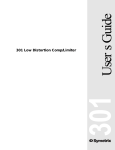
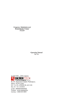
372 SPL Computer
U
S
E
R
N
G
U
I
D
E
372 SPL Computer User’s Guide
© January 2001 Symetrix, Inc.
All rights reserved.
Printed in the United States of America
Symetrix Part Number 53372-0C00
The information in this guide is subject to
change without notice. Symetrix, Inc. shall
not be liable for technical or editorial
errors or omissions contained herein; nor
is it liable for incidental or consequential
damages resulting from the furnishing,
performance, or use of this material.
Mention of third-party products is for informational purposes only and constitutes
neither an endorsement nor a recommendation. Symetrix assumes no responsibility with regard to the performance or use
of these products.
Under copyright laws, no part of this user
guide may be reproduced or transmitted
in any form or by any means, electronic or
mechanical, without permission in writing
from Symetrix, Inc. If, however, your only
means of access is electronic, permission
to print one copy is hereby granted.
Permission to copy the Architects and
Engineers Specificiations for written
proposals specifying equipment for sound
reinforcement systems is, also, granted.
Symetrix, Inc.
6408 216th St. SW
Mountlake Terrace WA 98043
USA
Tel:
425.778.7728
Fax:
425.778.7727
Web:
www.symetrixaudio.com
Email: [email protected]
Symetrix 372 SPL Computer User’s Guide
Contents
Before You Begin
2
Gap Threshold
20
What Ships in the Box
2
Force Sense Time
20
Getting Help
2
AGC
20
Optional Rackmount Accessories
2
Trigger Input
21
Notational Conventions in this User Guide
2
Setup Unlocked
21
Operational Safety Summary
3
Equipment Markings
3
Calibrating the 372
22
Features of the 372
4
Conditions Under Which the 372
Will Not Sense
23
Checklist of Tasks for Hardware Connections,
System Setup, and Calibration
5
Signal Flow Diagram
24
Making Hardware Connections
6
Input and Output Connector Wiring
25
Overview of Rear Panel Connectors and Connections
6
Troubleshooting
26
Sensing Speaker Considerations
8
372 Basic Connection
9
Hardware Specifications
28
Architects and Engineers Specifications
29
Connecting an External Relay to Drive Amplifiers
Larger than 200W
10
Connecting Up to 20 Slaves
11
Connecting an External Relay to Attach Slaves
12
Warranty
30
Connecting a Push Button Switch to Force or
Prevent Sensing
13
Service
31
System Setup
14
Declaration of Conformity
32
Overview of Front Panel
14
How System Setup Works
15
Description of Menu Features
16
Operating Mode
16
Status
18
History
18
Listen
18
Set MIN Limit
19
Set MAX Limit
19
Averaging Time
19
Gain: Sense Ratio
19
1
Symetrix 372 SPL Computer User’s Guide
Before You Begin
| What Ships in the Box | Getting Help | Optional Rackmount Accessories | Notational
Conventions in this User Guide | Operator Safety Summary | Equipment Markings
What Ships in the Box
Getting Help
The 372 unit
If you have questions beyond the scope of this guide, contact our Customer
Service Department in the following ways:
One PS-3 or PS-3E (export
version) power supply
T
US customers (425) 778-7728
International customers (425) 778-7728
8:00 am to 4:30 pm Monday through Friday, Pacific Time
F
(425) 778-7727
This user’s guide
[email protected]
www.symetrixaudio.com
Optional Rackmount Accessories
MODEL
ITEM
DESCRIPTION
RM-3
19" Rackmount Tray
1U shelf
FP-3
Filler Panel
Covers unused half of rack tray when
one 372 unit is mounted
PY-3
Y Power Cable
Connects a 372 with any other 300
Series product
Contact your dealer or Symetrix for purchasing information.
Notational Conventions in this User Guide
Note
Identifies information that needs extra emphasis. Generally
supplies extra information to help you to better use the 372.
CAUTION
Identifies information that, if ignored, may cause damage to
the 372 or other equipment in your system.
WARNING
Identifies information that, if ignored, may be hazardous to
your health or that of others.
SMALL CAPS Controls, switches or other markings on the chassis of the 372.
Bold Face
Indicates menu option in the 372 LCD display.
2
Symetrix 372 SPL Computer User’s Guide
Before You Begin
| What Ships in the Box | Getting Help | Optional Rackmount Accessories | Notational
Conventions in this User Guide | Operator Safety Summary | Equipment Markings
Operator Safety Summary
Follow all warnings and instructions. Install
in accordance with the manufacturer’s
instructions.
Power Source This product is intended
to operate from a Symetrix PS-3 or PS-3E
power supply.
Grounding The chassis of this product is
grounded through the grounding conductor of the PS-3 or PS-3E power cord. To
avoid electric shock, plug the power cord
into a properly wired receptacle before
making any connections to the product. A
protective ground connection, by way of
the grounding conductor in the power
cord, is essential for safe operation. Do
not defeat the safety purpose of the
grounding plug. The grounding plug has
two blades and a third grounding prong.
The third prong is provided for your
safety. When the provided plug does not
fit your outlet, consult an electrician for
replacement of the obsolete outlet.
Danger from Loss of Ground If the
protective ground connection is lost, all
accessible conductive parts, including
knobs and controls that may appear to be
insulated, can render an electric shock.
Proper Power Cord Use only the power
cord and connector specified for the
product and your operating locale. Use
only a cord that is in good condition.
Protect the power cord from being walked
on or pinched, particularly at the plug,
convenience receptacle, and the point
where the cord exits from the apparatus.
Equipment Markings
Operating Location Do not operate this
equipment under any of the following
conditions: explosive atmospheres, in wet
locations, in inclement weather, improper
or unknown AC mains voltage, or if
improperly fused. Do not install near any
heat source such as radiators, heat
registers, stoves, or other apparatus
(including amplifiers) that produce heat.
Unplug this apparatus during lightning
storms or when unused for long periods of
time.
Stay Out of the Box To avoid personal
injury (or worse), do not remove the
product covers or panels. Do not operate
the product without the covers and panels
properly installed. Only use accessories
specified by the manufacturer. Clean only
with a damp cloth.
User-serviceable parts There are no
user serviceable parts inside the 372. In
case of failure, refer all servicing to the
factory. Servicing is required when the
372 has been damaged in any way, such
as when a power supply cord or plug is
damaged, liquid has been spilled or
objects have fallen into the apparatus, the
apparatus has been exposed to rain or
moisture, does not operate normally, or
has been dropped.
CAUTION
RISK OF ELECTRIC SHOCK
DO NOT OPEN
TO REDUCE THE RISK OF FIRE OR
SHOCK DO NOT EXPOSE
WARNING: ELECTRIC
THIS EQUIPMENT TO RAIN OR MOISTURE
DE CHOC ELECTRIQUE
AVIS: RISQUE
NE PAS OUVRIR
SEE OWNERS MANUAL. VOIR CAHIER D’INSTRUCTIONS.
No user serviceable parts inside. Refer servicing to qualified service personnel.
Il ne se trouve a l’interieur aucune piece pourvant entre reparée l’usager.
S’adresser a un reparateur compétent.
The lightning flash with arrowhead symbol
within an equilateral triangle is intended
to alert the user of the presence of
uninsulated “dangerous voltage” within
the product’s enclosure that may be of
sufficient magnitude to constitute a risk of
electric shock to persons. The exclamation
point within an equilateral triangle is
intended to alert the user of the presence
of important operating and maintenance
(servicing) instructions in the literature
accompanying the product (i.e., this user’s
guide).
CAUTION
To prevent electric shock, do not use the
polarized plug supplied with the unit with
any extension cord, receptacle, or other
outlet unless the blades can be fully
inserted.
3
Symetrix 372 SPL Computer User’s Guide
Features of the 372
Uses Speakers for Noise Sensing
In less than 1 second, the Symetrix 372 temporarily opens up the amplifier
connection and routes the loudspeakers to a preamplifier for the purpose of
measuring changes in the ambient noise level. Samples during absence of page
and/or music audio, or at preset intervals.
Headphone Monitoring
Monitor the sense signal using a separate front panel headphone output.
5 Operating Modes
MUSIC
Music only or music + page. Use Gap and/or Force Sense Time.
PAGE
Only paging and annoucement audio. Use Force Sense Time at
preset intervals.
SLAVE
Forces all 372 units in a multi-zone system to execute a sense
sample at the same time.
HISTORY
Records and displays the lowest and highest SPL readings from when
the unit was last reset.
BYPASS
Bypasses the gain control of the SPL controller and the AGC.
Signal Path
Controls mono or stereo signals through Euroblock connectors.
Programmable Sensing Operation
Select the auto-sense mode and/or the time interval between sense samples.
Simple Calibration
Use step-through menus on the front panel LCD. Perform calibration under
typical installation conditions. No waiting for the quietest or noisiest ambient
environment.
AGC Control
Enables or disables auto leveling of input signals.
Ambient Adjustment
Choose an adjustment ratio of SPL change vs. program level change.
Sense Signal Monitoring
Display numeric reading and relative bargraph of the signal appearing at the
sense terminals.
Listen to sense signal with headphones connected to front panel mono output.
Gain Controls
Set minimum and maximum limits for SPL gain range. Gain range is +20 to –30 db.
Averaging Time
Choose integration time of the running average SPL.
4
Symetrix 372 SPL Computer User’s Guide
Checklist of Tasks for Hardware Connections,
System Setup, and Calibration
REQUIRED
HARDWARE
CONNECTIONS
SYSTEM SETUP
RECOMMENDED
TASK TO DO
Connecting input sources
Connecting output sources (use Symetrix 303 for
unbalanced outputs)
Connecting speaker for sensing and music/paging
Connecting speaker for either music or paging; does not
sense
Connecting an external relay if maximum amplifier
voltage and wattage exceeded
Connecting slave 372s
Connecting a switch or contact closure to manually force
or prevent sensing
Choose Operating Mode*
View calibration Status
Collect History of highest and lowest SPLs
Set gain level in Listen
Set MIN limit (gain)
Set MAX limit (gain)
Specify number of samples in Averaging Time
Specify Gain: Sense Ratio
Set Gap Threshold
Specify time for Force Sense Time
CALIBRATION
OPTIONAL
Enable AGC
Specify type of Trigger Input
Lock or Unlock Setup
Equating ambient noise level to 0 db (Unity) gain
*Bold face indicates menu name in LCD display
5
Symetrix 372 SPL Computer User’s Guide
Making Hardware Connections
| Overview of Rear Panel Connectors and Connections | Sensing Speaker Considerations
| 372 Basic Connection | Connecting an External Relay to Drive Amplifiers Larger than 200W
| Connecting Up to 20 Slaves | Connecting an External Relay to Attach Slaves
| Connecting a Push Button Switch to Force or Prevent Sensing
FROM AMP
TO SPEAKER
SENSE
POWER
INPUT
LINE OUTPUT
RIGHT
LEFT
LINE INPUT
RIGHT
LEFT
372
TRIGGER
EXT. RELAY
CONNECT TO
SYMETRIX
PS-3 OR PS-3E
POWER
SUPPLY ONLY
Overview of Rear Panel Connectors and Connections
CONNECTION
CONNECTOR TYPE
WHAT IT DOES
Power Input
7-pin DIN connector
Accepts power only from Symetrix
PS-3 or PS-3E power supply.
FROM AMP
2 terminal barrier strip
Accepts signal from power amplifier.
This output may be grounded or
bridged. 8A maximum current rating.
If your speaker load exceeds the
following ratings, you will need to use
an external relay (See Connecting an
External Relay to Attach Slaves).
MAX AMPLIFIER OUTPUT RATINGS
16 ohms
400W
70V
300W
8 ohms
200W
4 ohms
100W
TO SPEAKER
SENSE
2 terminal barrier strip
Delivers signal to loudspeaker system.
Do not ground either of these terminals.
EXT RELAY
Euroblock terminals
Open-collector drive signal for external sense relay. Can power amplifiers
larger than 200W at 8 ohms (See
Connecting an External Relay to
Attach Slaves). Controls as many as
20 slave 372 units directly from the
EXT RELAY output of the master 372.
This output can also drive the TRIGGER
input.
GROUND
Euroblock terminals
Ground return for external relay and
trigger.
TRIGGER
Euroblock terminals
Active low input forces sense event.
Can force or prevent a sense event
manually (See Connecting a Push
Button Switch to Force or Prevent
Sensing). Is internally pulled to the 5V
supply by way of a 20k ohm resistor.
From this connection attach slave 372
units to the master 372.
6
Symetrix 372 SPL Computer User’s Guide
Making Hardware Connections
| Overview of Rear Panel Connectors and Connections | Sensing Speaker Considerations
| 372 Basic Connection | Connecting an External Relay to Drive Amplifiers Larger than 200W
| Connecting Up to 20 Slaves | Connecting an External Relay to Attach Slaves
| Connecting a Push Button Switch to Force or Prevent Sensing
CONNECTION
CONNECTOR TYPE
WHAT IT DOES
LINE OUTPUT
Euroblock terminals
These connectors deliver a differential
balanced output at 200 ohm source
impedance. For unbalanced use, use
the positive line output terminals and
the ground terminals. Ignore (float)
the minus output terminals.
The output stage is a pair of opamps,
with the plus and minus output
terminals at 180° antiphase with each
other. It emulates a grounded centertap transformer. The series build-out
resistors are 100 ohms in each leg.
For wiring diagram, see the section
Input and Output Connector Wiring.
LINE INPUT
Euroblock terminals
Balanced input for the 372. 20k ohm
balanced bridging. For unbalanced
sources, connect the minus input
terminal to the source ground at the
source.
Note
Feeding unbalanced inputs directly from
balanced outputs is not recommended
due to the possibility of ground loops.
You may want to use the Symetrix 303
isolation transformer to break the
ground connection and eliminate the
ground loop.
With unbalanced sources, it is preferable
to carry the low side of the input all the
way back to the ground connection of
the source.
For wiring diagram, see the section
Input and Output Connector Wiring.
7
Symetrix 372 SPL Computer User’s Guide
Making Hardware Connections
| Overview of Rear Panel Connectors and Connections | Sensing Speaker Considerations
| 372 Basic Connection | Connecting an External Relay to Drive Amplifiers Larger than 200W
| Connecting Up to 20 Slaves | Connecting an External Relay to Attach Slaves
| Connecting a Push Button Switch to Force or Prevent Sensing
Sensing Speaker Considerations
Speaker Location
70V Systems
4, 8, and 16 Ohm Systems
If a sensing speaker is located near a
localized noise source that is not
typical for the ambient noise level of
the controlled zone, the 372 determines that the zone is noiser than it
really is. For example, the noise from
a large machine of some sort, or
maybe a kids play area, or a video
game. The solution is to have the
speakers that are near the noise
source driven directly from the
amplifier so that they are not used
for sensing.
In a 70V system, the signal level
returned by the speakers when the
372 is sensing is higher, because of
the step-up action of the line transformers. With highly-efficient speakers, this may present the problem of
overloading the sense input of the
372. Use the Listen mode to check
the level of the signal while the 372
senses. You may need to lower the
gain position of the AMBIENT SENSE
GAIN switch. More information about
the gain setting is found in Listen
under the section System Setup.
In these speaker impedance systems,
the signal levels returned to the 372
are low. Use the Listen mode to
check the level of the signal while the
372 senses. You may need to select
the high gain position of the AMBIENT
SENSE GAIN switch.
A common practice in 70V systems is
to provide autotransformers or L-pads
after the line transformer to allow
local volume control. These controls
should not be used with the 372.
Allowing any sort of signal level
control after the 372 invalidates your
calibration settings. If you must
provide a local control, then ensure
that the controlled zone is a minor
part of the entire system. In this
controlled zone, volume level will not
be ideal and sensing should not be
used.
Also, it is imperative that every
speaker and transformer in the
system operate in-phase.
8
Symetrix 372 SPL Computer User’s Guide
Making Hardware Connections
| Overview of Rear Panel Connectors and Connections | Sensing Speaker Considerations
| 372 Basic Connection | Connecting an External Relay to Drive Amplifiers Larger than 200W
| Connecting Up to 20 Slaves | Connecting an External Relay to Attach Slaves
| Connecting a Push Button Switch to Force or Prevent Sensing
372 Basic Connection
Signal I/O Connections
These connectors are designed for
use with bare wire. Do not tin strand
wires before inserting them into the
connectors.
Connect all speakers used for sensing
and either music or paging to this
output.
If using unbalanced connections, see
wiring diagram in the section Input
and Output Connector Wiring.
1
Connect your line-level source to
the rear-panel input connectors.
The relay contacts handle 8A
continuous current.
3
FROM AMP
SENSE
TRIGGER
EXT. RELAY
POWER
INPUT
LINE INPUT
RIGHT
LEFT
3
2
1
Connect the outputs as required.
These connectors deliver a
differential balanced output signal.
For unbalanced use, use the
positive line output terminals and
the ground terminals. Ignore
(float) the minus output terminals.
Input Source
Amplifier
Connect all speakers that do not sense
to the amplifier output.
Amplifier and Speaker
Connections
3
LINE OUTPUT
RIGHT
LEFT
CONNECT TO
SYMETRIX
PS-3 OR PS-3E
POWER
SUPPLY ONLY
These connectors may be driven
from a balanced or unbalanced
source. When using an unbalanced source, connect the output
minus terminal to ground either at
the source or at the 372.
2
TO SPEAKER
372
Note
Feeding unbalanced inputs directly from
balanced outputs is not recommended
due to the possibility of ground loops.
An option is to use the Symetrix 303
isolation transformer to break the
ground connection and eliminate the
ground loop.
These speakers are required.
Connect your amplifier and
speakers to the barrier strip
connectors.
Use these speakers for only music or
paging.
These speakers are optional.
The speaker and amplifier connections are earth-free (floating).
The 372 treats the speaker
connections after its sensing relay
as if they were a balanced line.
Do not ground either side of the
speaker line. It is OK if the one
side of the amplifier output is
grounded.
9
Symetrix 372 SPL Computer User’s Guide
Making Hardware Connections
| Overview of Rear Panel Connectors and Connections | Sensing Speaker Considerations
| 372 Basic Connection | Connecting an External Relay to Drive Amplifiers
Larger than 200W | Connecting Up to 20 Slaves | Connecting an External Relay to Attach Slaves
| Connecting a Push Button Switch to Force or Prevent Sensing
Connecting an External Relay to Drive Amplifiers Larger than 200W
When controlling amplifiers larger
than 200W, you must use an external
DPDT relay. The internal relay of the
372 cannot handle more than 8A of
load current.
External DC
Coil Relay
Low (–)
Low (–)
High (+)
High (+)
RECOMMENDED MAXIMUM
AMPLIFIER WATTAGES
300W
70V
200W
8 ohms
100W
4 ohms
You must supply power for the relay
and the relay must have a backbiased 1N4002 diode connected
across its coil to absorb the back EMF
from the relay coil. The transistor has
a 60V VCE rating (MPSA 06).
DC
Power
Supply
(–)
16 ohms
(+)
400W
Amplifier
1N4002 or
Equivalent
Diode
FROM AMP
POWER
INPUT
TO
SPEAKER
CONNECT TO
SYMETRIX
PS-3 OR PS-3E
POWER
SUPPLY ONLY
The 24V version of the Potter &
Brumfield PRD11DGO works well. Its
DPDT contacts are rated at 30A.
10
SENSE
TRIGGER
EXT. RELAY
LINE OUTPUT
RIGHT
LEFT
LINE INPUT
RIGHT
LEFT
Symetrix 372 SPL Computer User’s Guide
Making Hardware Connections
| Overview of Rear Panel Connectors and Connections | Sensing Speaker Considerations
| 372 Basic Connection | Connecting an External Relay to Drive Amplifiers Larger than 200W
| Connecting Up to 20 Slaves | Connecting an External Relay to Attach Slaves
| Connecting a Push Button Switch to Force or Prevent Sensing
Connecting Up to 20 Slaves
Master 372
A master 372 can direct any number
of slave 372 units to take an ambient
sample. You can parallel slave 372
units directly together from the
master unit to enable you to sense at
the same time in adjacent or multiple
installation zones. If the slave 372
units are in remote locations, use an
external relay to connect the slaves
to the master unit (see Connecting an
External Relay to Attach Slaves).
TO SPEAKER
FROM AMP
As many as 20 slave 372 units may
be controlled directly from the master
372.
LINE OUTPUT
RIGHT
LEFT
LINE INPUT
RIGHT
LEFT
CONNECT TO
SYMETRIX
PS-3 OR PS-3E
POWER
SUPPLY ONLY
372
POWER
INPUT
SENSE
TRIGGER
EXT. RELAY
Slave 372
MAXIMUM CABLE LENGTH
FROM AMP
POWER
INPUT
TO SPEAKER
SENSE
TRIGGER
EXT. RELAY
LINE OUTPUT
RIGHT
LEFT
LINE INPUT
RIGHT
LEFT
CONNECT TO
SYMETRIX
PS-3 OR PS-3E
POWER
SUPPLY ONLY
372
IMPORTANT!
As of 372 hardware revision C, an
internal jumper (J8) has been added
which must be in correctly configured on the master 372 in order to
properly drive the slaves.
Moving J8 to connect pins 2 and
3 configures the TRIGGER input
connection on the Master 372 to
become a Slave Drive OUTPUT. This
reconfiguration is necessary to prevent a "false sensing" problem when
multiple zones bleed into each other.
This new way of configuring the
master 372 ensures that all 372's
will sense in sync thus avoiding false
sense readings from zone bleed.
From the front panel of the slave 372
LCD menu display:
POWER
INPUT
CONNECT TO
SYMETRIX
PS-3 OR PS-3E
POWER
SUPPLY ONLY
POWER
INPUT
CONNECT TO
SYMETRIX
PS-3 OR PS-3E
POWER
SUPPLY ONLY
POWER
INPUT
CONNECT TO
SYMETRIX
PS-3 OR PS-3E
POWER
SUPPLY ONLY
POWER
INPUT
CONNECT TO
SYMETRIX
PS-3 OR PS-3E
POWER
SUPPLY ONLY
Press NEXT to gain access to Operating
Mode.
Rotate ADJUST to select Slave mode.
FROM AMP
TO SPEAKER
FROM AMP
TO SPEAKER
FROM AMP
TO SPEAKER
FROM AMP
TO SPEAKER
FROM AMP
TO SPEAKER
SENSE
LINE OUTPUT
RIGHT
LEFT
LINE INPUT
RIGHT
LEFT
SENSE
LINE OUTPUT
RIGHT
LEFT
LINE INPUT
RIGHT
LEFT
SENSE
LINE OUTPUT
RIGHT
LEFT
LINE INPUT
RIGHT
LEFT
SENSE
LINE OUTPUT
RIGHT
LEFT
LINE INPUT
RIGHT
LEFT
SENSE
LINE OUTPUT
RIGHT
LEFT
LINE INPUT
RIGHT
LEFT
TRIGGER
EXT. RELAY
372
CONNECT TO
SYMETRIX
PS-3 OR PS-3E
POWER
SUPPLY ONLY
TRIGGER
EXT. RELAY
372
Connect the other end of the cable to
the TRIGGER input and Ground terminals
of each slave unit in parallel.
POWER
INPUT
TRIGGER
EXT. RELAY
372
Connect a cable from TRIGGER and
Ground terminals of the master unit.
TRIGGER
EXT. RELAY
372
On the master 372, remove the top
and move the jumper (J8) to connect pins 2 and 3. (Pins 1 and 2
are connected at the factory. This is
the default position and this jumper
should only be changed on the master 372. J8 should remain in the factory default position on all slaves).
Slave Group up to 20 units
Press NEXT to locate Trigger Input.
Check to see that Force Sense is selected.
(Force Sense is the default setting.)
(See Operating Mode—Slave in the
section System Setup for additional
information)
11
TRIGGER
EXT. RELAY
372
Depends upon the difference in
ground potential (if any) between the
individual units.
Symetrix 372 SPL Computer User’s Guide
Making Hardware Connections
| Overview of Rear Panel Connectors and Connections | Sensing Speaker Considerations
| 372 Basic Connection | Connecting an External Relay to Drive Amplifiers Larger than 200W
| Connecting Up to 20 Slaves | Connecting an External Relay to Attach Slaves
| Connecting a Push Button Switch to Force or Prevent Sensing
Connecting an External Relay to Attach Slaves
Master 372
Use an External Relay:
To connect more than 20 slave 372
units together from the master unit to
sense at the same time in adjacent or
multiple installation zones.
FROM AMP
POWER
INPUT
TO SPEAKER
SENSE
TRIGGER
EXT. RELAY
LINE OUTPUT
RIGHT
LEFT
LINE INPUT
RIGHT
LEFT
372
CONNECT TO
SYMETRIX
PS-3 OR PS-3E
POWER
SUPPLY ONLY
—or—
To connect slave 372 units in remote
locations from the master unit.
External Relay Pack
If some of the slave units are a long
distance away from the master, a
direct connection might give rise to
ground loop problems. To avoid this,
use an external relay to isolate the
connection between the master and
the distant slaves.
Sen
FROM AMP
SENSE
TRIGGER
EXT. RELAY
LINE OUTPUT
RIGHT
LEFT
Sen
LINE INPUT
RIGHT
LEFT
CONNECT TO
SYMETRIX
PS-3 OR PS-3E
POWER
SUPPLY ONLY
POWER
INPUT
CONNECT TO
SYMETRIX
PS-3 OR PS-3E
POWER
SUPPLY ONLY
POWER
INPUT
CONNECT TO
SYMETRIX
PS-3 OR PS-3E
POWER
SUPPLY ONLY
POWER
INPUT
CONNECT TO
SYMETRIX
PS-3 OR PS-3E
POWER
SUPPLY ONLY
POWER
INPUT
CONNECT TO
SYMETRIX
PS-3 OR PS-3E
POWER
SUPPLY ONLY
POWER
INPUT
CONNECT TO
SYMETRIX
PS-3 OR PS-3E
POWER
SUPPLY ONLY
LINE OUTPUT
RIGHT
LEFT
LINE INPUT
RIGHT
LEFT
TO SPEAKER
SENSE
TRIGGER
EXT. RELAY
LINE OUTPUT
RIGHT
LEFT
TO SPEAKER
SENSE
TRIGGER
EXT. RELAY
LINE OUTPUT
RIGHT
LEFT
TO SPEAKER
SENSE
TRIGGER
EXT. RELAY
LINE OUTPUT
RIGHT
LEFT
TO SPEAKER
SENSE
TRIGGER
EXT. RELAY
LINE OUTPUT
RIGHT
LEFT
POWER
INPUT
CONNECT TO
SYMETRIX
PS-3 OR PS-3E
POWER
SUPPLY ONLY
POWER
INPUT
CONNECT TO
SYMETRIX
PS-3 OR PS-3E
POWER
SUPPLY ONLY
POWER
INPUT
CONNECT TO
SYMETRIX
PS-3 OR PS-3E
POWER
SUPPLY ONLY
POWER
INPUT
CONNECT TO
SYMETRIX
PS-3 OR PS-3E
POWER
SUPPLY ONLY
POWER
INPUT
CONNECT TO
SYMETRIX
PS-3 OR PS-3E
POWER
SUPPLY ONLY
LINE INPUT
RIGHT
LEFT
372
FROM AMP
CONNECT TO
SYMETRIX
PS-3 OR PS-3E
POWER
SUPPLY ONLY
LINE INPUT
RIGHT
LEFT
372
FROM AMP
POWER
INPUT
LINE INPUT
RIGHT
LEFT
372
FROM AMP
CONNECT TO
SYMETRIX
PS-3 OR PS-3E
POWER
SUPPLY ONLY
LINE INPUT
RIGHT
LEFT
372
FROM AMP
POWER
INPUT
FROM AMP
TO SPEAKER
FROM AMP
TO SPEAKER
FROM AMP
TO SPEAKER
FROM AMP
TO SPEAKER
FROM AMP
TO SPEAKER
FROM AMP
TO SPEAKER
FROM AMP
TO SPEAKER
SENSE
LINE OUTPUT
RIGHT
LEFT
LINE INPUT
RIGHT
LEFT
SENSE
LINE OUTPUT
RIGHT
LEFT
LINE INPUT
RIGHT
LEFT
SENSE
LINE OUTPUT
RIGHT
LEFT
LINE INPUT
RIGHT
LEFT
SENSE
LINE OUTPUT
RIGHT
LEFT
LINE INPUT
RIGHT
LEFT
SENSE
LINE OUTPUT
RIGHT
LEFT
LINE INPUT
RIGHT
LEFT
SENSE
LINE OUTPUT
RIGHT
LEFT
LINE INPUT
RIGHT
LEFT
SENSE
LINE OUTPUT
RIGHT
LEFT
LINE INPUT
RIGHT
LEFT
TRIGGER
EXT. RELAY
372
CONNECT TO
SYMETRIX
PS-3 OR PS-3E
POWER
SUPPLY ONLY
SENSE
TRIGGER
EXT. RELAY
TRIGGER
EXT. RELAY
372
POWER
INPUT
TO SPEAKER
TRIGGER
EXT. RELAY
372
CONNECT TO
SYMETRIX
PS-3 OR PS-3E
POWER
SUPPLY ONLY
372
FROM AMP
POWER
INPUT
Slave Group 2
Press NEXT to gain access to Operating
Mode.
Rotate ADJUST to select Slave mode.
4
Sen
TRIGGER
EXT. RELAY
372
POWER
INPUT
TO SPEAKER
Connect cables from the external relay
outputs to the TRIGGER and Ground
terminals of each slave unit in parallel.
From the front panel of the slave 372
LCD menu display:
3
Sen
Slave 372
Slave Group 1
Connect a cable from TRIGGER and
Ground terminals of the master unit to
the External Relay control and Ground
terminals on the rear panel of the
external relay.
2
TRIGGER
EXT. RELAY
372
Please see notes on previous page
regarding internal jumper configuration of the master 372.
Slaved Groups
1
372
IMPORTANT!
Ext
Relay
Control
Press NEXT to locate Trigger Input.
SENSE
LINE OUTPUT
RIGHT
LEFT
LINE INPUT
RIGHT
LEFT
372
TRIGGER
EXT. RELAY
FROM AMP
TO SPEAKER
SENSE
TRIGGER
EXT. RELAY
LINE OUTPUT
RIGHT
LEFT
LINE INPUT
RIGHT
LEFT
12
TRIGGER
EXT. RELAY
372
TO SPEAKER
TRIGGER
EXT. RELAY
372
(See Description of Menu Features,
Operating Mode—Slave in the section
System Setup for additional information)
FROM AMP
372
Check to see that Force Sense is selected.
(Force Sense is the default setting.)
Symetrix 372 SPL Computer User’s Guide
Making Hardware Connections
| Overview of Rear Panel Connectors and Connections | Sensing Speaker Considerations
| 372 Basic Connection | Connecting an External Relay to Drive Amplifiers Larger than 200W
| Connecting Up to 20 Slaves | Connecting an External Relay to Attach Slaves
| Connecting a Push Button Switch to Force or Prevent Sensing
Connecting a Push Button Switch to Force or Prevent Sensing
You can manually prevent sensing or
manually control sensing by using a
push button switch.
FROM AMP
TO SPEAKER
SENSE
TRIGGER
EXT. RELAY
POWER
INPUT
LINE OUTPUT
RIGHT
LEFT
LINE INPUT
RIGHT
LEFT
372
In conjunction with the TRIGGER
connection on the rear panel, you
must also choose Trigger Input in
the LCD menu display to enable either
a force sense or prevent sense event.
CONNECT TO
SYMETRIX
PS-3 OR PS-3E
POWER
SUPPLY ONLY
Prevent Sense is useful in the Music
mode during voice announcements, in
conjunction with an external contact
closure. In Music mode the 372 has
no other way to know if an announcement is happening.
An example of an external contact
closure might be a spare set of
contacts on a push-to-talk microphone. The 372 is prevented from
sensing the ambient room level
whenever these contacts are pressed
closed. Otherwise, a timed sense
event might “cut off” the announcer
when he/she is speaking.
Push Button Switch
To Force a Sense Event
Connect a momentary contact closure
between the TRIGGER and Ground
terminals.
From the front panel of the slave 372
LCD menu display:
Press NEXT to gain access to Trigger
Input.
Check to see that Force Sense is selected.
(Force Sense is the default setting.)
(For additional information, see in the
section System Setup, Description of
Menu Features—Trigger Input)
To Prevent a Sense Event
Connect a normally-open set of switch
or relay contacts between the TRIGGER
and Ground terminals.
From the front panel of the slave 372
LCD menu display:
Press NEXT to gain access to Trigger
Input.
Rotate ADJUST to select Prevent Sense.
(For additional information, see in the
section System Setup, Description of
Menu Features—Trigger Input)
13
Symetrix 372 SPL Computer User’s Guide
System Setup
| Overview of Front Panel | How System Setup Works | Description of Menu Features
SETUP
AMBIENT SENSE
ADJUST
MENU
372
NEXT
CAL
MONITOR
GAIN
EXIT
SPL
COMPUTER
HIGH
MID
LOW
Overview of Front Panel
CONTROL
CONTROL TYPE
WHAT IT DOES
SETUP
LCD menu display
Two line display shows levels and
settings of selected menu feature.
NEXT
From normal operation, the first press
enters the setup mode; subsequent
presses step through the setup process.
EXIT
Exits the setup mode. The unit reverts
to normal operation.
ADJUST
Rotary control used in setup mode for
parameter setting.
CAL
Press to have the 372 read the
current ambient level and equate this
reading to 0 db (Unity) gain. Displays
the relative ambient reading which it
considers as normal. CAL is only
active in normal operating mode and
when setup is unlocked.
Headphone jack
1/4 inch TRS jack suitable for headphone impedances of 60 ohms or
higher, stereo or mono. Enables
listening to the output of the sensing
system when 372 is in Listen mode.
Helpful for troubleshooting or for
figuring out what the 372 is listening
to. For more information, see
Description of Menu Features, Operating Mode—Listen.
MONITOR
Adjusts the volume level at the
headphone jack.
GAIN
3-position switch adjusts the sensitivity of the sensing circuitry to accommodate different conditions. Set the
gain level while in the Listen mode.
For more information, see Description
of Menu Features, Operating Mode—
Listen.
AMBIENT SENSE
Note
Once the 372 has been set up, do not
change the AMBIENT SENSE GAIN position.
14
Symetrix 372 SPL Computer User’s Guide
System Setup
| Overview of Front Panel | How System Setup Works | Description of Menu Features
How System Setup Works
Use the two push buttons, NEXT and
EXIT, with the parameter adjustment
knob, ADJUST, to gain access to menu
setup options in the LCD display.
REQUIRED
RECOMMENDED
OPTIONAL
MENU FEATURE IN LCD DISPLAY
Choose Operating Mode*
1
Press NEXT to enter the setup
mode.
View calibration Status
2
Rotate ADJUST to select a specific
value or choice.
Collect History of highest and lowest
SPLs
3
Press NEXT again to gain access
to another menu option. Subsequent presses of Next change
menu options.
4
Press EXIT to end the setup
process, save any changes made,
and return the unit to normal
operation.
Set gain level in Listen
Set MIN limit (gain)
Set MAX limit (gain)
—or—
Allow 30 seconds of inactivity,
after which the unit returns to
normal operation. (Does not
apply while using the Listen
feature.)
5
Specify Averaging Time
Specify Gain: Sense Ratio
Set Gap Threshold
Specify time for Force Sense Time
After setup is complete, calibrate
the unit (See the section Calibrating the 372).
Enable AGC
Specify type of Trigger Input
Lock or Unlock Setup
*Bold face indicates menu name in LCD display
15
Symetrix 372 SPL Computer User’s Guide
System Setup
| Overview of Front Panel | How System Setup Works | Description of Menu Features
Description of Menu Features
PRESS NEXT TO SELECT MENU FEATURE
ROTATE ADJUST TO
SELECT VALUE OR
CHOICE
Music
Operating Mode
DESCRIPTION
This mode considers everything as if it were music,
even though it may contain a mix of music and
announcement audio.
Varies the gain of this program channel to match the
ambient noise level.
How Sampling Works—Takes SPL measurements during
silent portions in the program material. If the 372 doesn’t
find gaps, then it forces a sense period (samples for about
0.75 seconds) after which, it restores the program channel
signal.
How You Can Control Sampling —You can force a sense
period manually and select the time of the forced event.
See Trigger Input in this section to enable this feature.
Can also perform simple AGC on the input signal to
improve the consistency of the output level. See AGC in
this section to enable this feature.
Page
Select this mode if you are doing paging or
announcement audio only.
Varies the gain of the program channel to match the
ambient noise level.
How Sampling Works—The presence of audio in the
program channel prevents sampling from taking place.
Sampling stays “locked out” until the program channel has
remained silent for at least 20 seconds. In the rare event
that a page or announcement begins while sampling is
taking place (samples for about 0.75 seconds), the current
sense cycle/period will complete and then further sampling
is prevented.
How You Can Control Sampling —If your application cannot
tolerate paging interuptions, you can force sensing to
occur after a page announcement. See Force Sense Time
in this section to enable this feature.
Can perform simple AGC on over-threshold compression
on the paging signal at 3:1 ratio on signals above 0 dBu
(defeatable). See AGC in this section to enable this
feature.
REQUIRED
RECOMMENDED
OPTIONAL
16
Symetrix 372 SPL Computer User’s Guide
System Setup
| Overview of Front Panel | How System Setup Works | Description of Menu Features
Description of Menu Features continues
PRESS NEXT TO SELECT MENU FEATURE
ROTATE ADJUST TO
SELECT VALUE OR
CHOICE
Operating Mode continues
Slave
DESCRIPTION
Select this mode if you want to designate the 372
unit as a slave. Slave units connected to a master
372 unit enable you to sense at the same time in
adjacent or multiple installation zones.
This mode senses only in response to an external sense
command received by way of the TRIGGER input connector
on the rear panel of the slave.
As many as 20 slave 372 units may be controlled directly
from the EXT RELAY output of the master 372. Connect a
cable from EXT RELAY and Ground terminals of the master
unit to the TRIGGER input and Ground terminals of each
slave unit in parallel (See Connecting Up to 20 Slaves).
More than 20 slave 372 units may be controlled using an
external relay (See Connecting an External Relay to Attach
Slaves).
If some of the slave units are a long distance away from
the master, a direct connection might give rise to ground
loop problems. To avoid this, use an external relay to
isolate the connection between the master and the distant
slaves (See Connecting an External Relay to Attach Slaves).
On the front panel of the slave units, press NEXT to locate
Trigger Input in the LCD menu display. Check to see that
Force Sense is selected. Force Sense is the default setting.
History
Select this mode if you only want the 372 to collect
data about the highest and lowest ambient SPL in
the installation zone(s).
The 372 does not perform any gain control in this mode.
You can determine the start of the history period or collection of data. See History later in this section to reset or
start the collection of the relative SPL history.
To view the current SPL readings, see Listen.
Bypass
Select this mode when you want to leave the 372
physically connected in the signal path, only pass
the signal unaltered, and never take SPL samples.
This feature is useful if you encounter setup problems in an
installation. You can temporarily disable the 372 until you
have the time to correct the problem. Or when the action
of the 372 is temporarily unwanted, for example, when an
unusual event is taking place.
You can view your control settings in this mode. Any
changes you make to your control settings in this mode,
will not take effect.
The gain is always held at unity (0 dB) in Bypass mode.
REQUIRED
RECOMMENDED
OPTIONAL
Bypass mode is not a hard-wire bypass.
17
Symetrix 372 SPL Computer User’s Guide
System Setup
| Overview of Front Panel | How System Setup Works | Description of Menu Features
Description of Menu Features continues
ROTATE ADJUST TO
SELECT VALUE OR
CHOICE
PRESS NEXT TO SELECT MENU FEATURE
Status
DESCRIPTION
Displays the current calibration status of the 372.
History
Cal Level
Ambient signal level measured at the last sense period.
Min Level
Minimum gain that the 372 is permitted to have.
Max Level
Maximum gain that the 372 is permited to have.
Reset to Zero
Displays numeric readings of the highest and lowest
SPLs from whenever the 372 unit was calibrated or
from when the setting was last reset.
Resetting the 372 to Zero starts a new history period,
where the 372 begins to collect the highest and lowest
relative SPL readings.
Listen
Select Listen in order to set the gain level.
There is a 2 second delay prior to entering this function.
The 372 switches the system into Listen mode, silencing
the speakers and using them as microphones to read the
ambient sound level.
The relative SPL reading then displays in numeric form
and, also, as a bargraph.
Adjust the AMBIENT SENSE GAIN switch on the front panel
until the indicated level is higher than at least –40 dB, but
no more than 0 dB. This setting range allows the 372 to
have enough valid information to control the system gain.
Note
Once the 372 has been set up, the AMBIENT SENSE GAIN switch
position should never be changed.
In this mode, you can plug in headphones to listen to the
ambient sound the 372 reads. Adjust the volume of the
headphones by rotating MONITOR.
The headphone is a helpful troubleshooting tool for identifying noise sources that may be misdirecting the 372 or
hum and noise picked up in the speaker wiring that may be
causing sense errors.
REQUIRED
RECOMMENDED
OPTIONAL
18
Symetrix 372 SPL Computer User’s Guide
System Setup
| Overview of Front Panel | How System Setup Works | Description of Menu Features
Description of Menu Features continues
PRESS NEXT TO SELECT MENU FEATURE
ROTATE ADJUST TO
SELECT VALUE OR
CHOICE
DESCRIPTION
Select value
To adjust the lowest gain setting that the 372 uses.
Set MIN Limit
This ensures a known minimum level from the sound
system, even if the ambient drops to dead silence.
Set MAX Limit
Select value
To adjust the highest gain setting that the 372 uses.
This ensures that the sound system stays out of clipping
even if the ambient level exceeds your wildest expectations.
Averaging Time
1, 2, 4, or 8
To average together the number of samples to make
a gain change.
Select the number of samples you want the 372 to use.
Longer running averages make the system respond more
to the trend of the ambient level rather than the most
recent sample.
Gain: Sense Ratio
0.5:1, 1:1,
1.5:1, or 2:1
Refers to the change in gain of the 372 versus the
change in the ambient.
0.5:1 changes gain 0.5 dB for every dB change in the
ambient. This makes the sound system louder in response
to increases in the ambient, but never tries to out-shout
the crowd.
1:1 matches gain changes to the ambient noise level.
1.5:1 changes gain 1.5 dB for every 1 dB increase in the
ambient noise level.
2:1 changes gain 2 dB for every 1 dB increase in the
ambient noise level.
At high ambient levels, the 372 can easily out-shout the
crowd if the control settings allow it. To limit the 372’s
ability to out-shout the crowd, pick a lower maximum gain
in Set MAX Limit.
At lower ambient levels, the 372 might let the sound
system get lost in the ambient. To avoid this, choose a
higher (closer to 0 dB) minimum gain in Set MIN Limit.
REQUIRED
RECOMMENDED
OPTIONAL
19
Symetrix 372 SPL Computer User’s Guide
System Setup
| Overview of Front Panel | How System Setup Works | Description of Menu Features
Description of Menu Features continues
PRESS NEXT TO SELECT MENU FEATURE
ROTATE ADJUST TO
SELECT VALUE OR
CHOICE
Select value
Gap Threshold
DESCRIPTION
To set the minimum signal level needed for the 372
to not detect silence in the program channel.
In Music mode, the 372 senses anytime that the music
program level falls below the Gap Threshold setting. If
there are no gaps in the program, then the 372 senses at
the interval set by the Force Sense Time, which ranges
from never to 30 minutes. See Force Sense Time.
In Page mode, the 372 senses when directed by the
Force Sense Time or by an external trigger source. Use
Gap Threshold to prevent sensing activity during paging.
If a page is in progress, the 372 will not interrupt it for
sensing.
Force Sense Time
To force a sensing period when the program material is too dense to contain sufficient gaps for
silence sensing.
Never, 1, 3, 5,
10, 20 or 30
minutes
Selections in Music mode.
Sense After Page, Selections in Page mode.
1, 3, 5, 10, 20
or 30 minutes
Choose Sense After Page in situations where paging is
frequent and uninterruptible. This selection triggers a
sense period about 20 seconds after the paging signal
level falls below the Gap Threshold setting.
You can also force a sense period manually by using an
external trigger source or contact closure connected to
TRIGGER on the rear panel (See Connecting a Push Button
Switch to Force or Prevent a Sense Event).
AGC
Enable or
Disable
Performs simple AGC on the input signal(s).
In Music mode, this action consists of low-ratio expansion
for signal levels below 0 dBu and moderate-ratio compression for signal levels above 0 dBu. This can be useful in
reducing the dynamic range of signal sources such as CD
players.
In Page mode, this action performs over-threshold
compression at 3:1 ratio for signals over 0 dBu as referred
to the input. This can be useful in keeping the sound
system out of clipping, or for reducing the surprise factor
caused by a loud talker.
REQUIRED
RECOMMENDED
OPTIONAL
20
Symetrix 372 SPL Computer User’s Guide
System Setup
| Overview of Front Panel | How System Setup Works | Description of Menu Features
Description of Menu Features continues
ROTATE ADJUST TO
SELECT VALUE OR
CHOICE
PRESS NEXT TO SELECT MENU FEATURE
Trigger Input
DESCRIPTION
You can manually prevent sensing or manually
control sensing by using this feature in conjunction
with the hardware connection, TRIGGER, on the rear
panel.
Force Sense
Forces a sense period when the program material is too
dense to contain sufficient gaps for silence sensing.
Operates independently of Gap Threshold. On the rear
panel, connect a momentary contact closure between
the TRIGGER and Ground terminals to initiate an ambient
level sense event (See Connecting a Push Button Switch
to Force or Prevent Sensing).
—or—
Enables slave 372s connected to a master 372 to sense at
the same time in adjacent or multiple zones (See Slave
mode in this section and in the section Making Hardware
Connections, see Connecting Up to 20 Slaves).
Prevent Sense
Useful in Music mode during voice announcements, in
conjunction with an external contact closure. In Music
mode the 372 has no other way to know if an announcement is happening.
Connect to the TRIGGER input a normally-open set of
switch or relay contacts between the TRIGGER and Ground
terminals on the rear panel. An example of this might be a
spare set of contacts on a push-to-talk microphone.
Whenever these contacts are pressed closed, the 372 is
prevented from sensing the ambient room level. Otherwise, a timed sense event might “cut off” the announcer
when he/she is speaking (See Connecting a Push Button
Switch to Force or Prevent Sensing).
Setup Unlocked
Not Used
Disables the trigger pin.
Unlock or lock
Choose to protect front panel LCD menu settings
from being altered.
To lock, press and hold CAL while rotating ADJUST. Once
it’s locked, pressing NEXT shows the current settings. Any
attempt to alter settings results in the display of the
message “Setup is Locked.”
To unlock, press NEXT until the display reads “Setup Is
Locked.” Press and hold CAL while rotating ADJUST. The
front panel is now unlocked.
REQUIRED
RECOMMENDED
OPTIONAL
21
Symetrix 372 SPL Computer User’s Guide
Calibrating the 372
To calibrate the 372
1
Choose a time when the ambient
noise in the area being controlled
is at a typical level.
2
On the front panel, press CAL.
The 372 reads the current
ambient level and equates this
reading to 0 dB (Unity) gain.
3
Whenever the SPL of the environment
is at this level, the program channel
of the 372 will be at 0 dB (Unity)
gain. As the ambient SPL becomes
less, the 372 lowers its gain. Conversely, when the SPL increases, the
gain of the 372 increases.
Only perform calibration when the
setup for the 372 is unlocked (See
Setup Unlocked in section System
Setup). Pressing CAL when the setup
is locked causes the 372 to report the
most current relative calibration level.
No settings are altered.
When calibration is finished, the
372 displays the relative ambient
SPL reading which it considers as
“Normal.”
22
Symetrix 372 SPL Computer User’s Guide
Conditions Under Which the 372
Will Not Sense
Because the 372 uses the speakers of
a sound system as sensing microphones, the sound system is briefly
disabled every time a reading is
taken. To keep these interruptions to
a minimum, the 372 follows several
rules to prevent sensing under
specific conditions.
The 372 Will Not Take Samples When:
1
In Music mode, whenever the program audio is above the Gap Threshold
level. (You can override the Gap Threshold level by manually controlling
sensing. See in Description of Menu Features, Trigger Input—Force
Sense in the section System Setup.)
2
In Page mode, whenever the program audio is above the Gap Threshold
level.
3
In Page mode, for about 20 seconds after any program signal above the
Gap Threshold level has disappeared.
4
In any mode, for about 4 seconds after the last sample was taken.
5
In any mode, as long as the TRIGGER input is grounded, if Prevent Sense
has been selected for Trigger Input in the LCD menu display.
6
In Bypass mode.
23
24
SENSE TRIGGER
AND
EXTERNAL RELAY
ADJUST
CALIBRATE
MENU EXIT
MENU NEXT
RIGHT
BALANCED
LINE IN
LEFT
BALANCED
LINE IN
8-BIT
CPU
CIRCUITRY
8-BIT
DAC
RMS
DETECTOR
TO
FROM
AMP SPEAKER
VCA
VCA
LCD DISPLAY
SWITCHABLE
ATTENUATOR
GAIN
ROOM SENSE
MONITOR
HIGH
MID
LOW
FILTERS
LEFT
BALANCED
LINE OUT
RMS
DETECTOR
RIGHT
BALANCED
LINE OUT
Symetrix 372 SPL Computer User’s Guide
Signal Flow Diagram
Symetrix 372 SPL Computer User’s Guide
Input and Output Connector Wiring
METHOD
CONNECTOR
CHANNEL
Balanced Terminal Strip
Input
Input
= Not Connected
= High
= Low
= Not Connected
132
Balanced Female XLR
Pin 1
Pin 2
Pin 3
Connector Shield
Input
Balanced TRS Plug
Tip
Ring
Sleeve
= High
= Low
= Shield
TIP
RING
SLEEVE
Input
Unbalanced TS Plug
Tip
Sleeve
TIP
= High
= Low + Shield
SLEEVE
Input
Unbalanced RCA Plug
Tip
Sleeve
Cable Shield
= High
= Low
= Not Connected
Output
= Circuit Ground
= High
= Low
231
Balanced Male XLR
Pin 1
Pin 2
Pin 3
Output
Unbalanced TS Plug
Tip
Sleeve
Wire Low
= High
= Shield
= Not Connected
TIP
SLEEVE
25
Symetrix 372 SPL Computer User’s Guide
Troubleshooting
SYMPTOM
PROBABLE CAUSE / WHAT TO DO
No output signal
Check cables and connections to see if:
• Inputs are driving outputs, and outputs are driving inputs.
• There is a signal coming from the source and that it is getting to the 372.
• The signal chain after the 372 is functioning.
Check if the LCD display is on and unit is plugged in.
Unit will not calibrate
Check that input levels are normal.
In Listen mode, use headphones to hear what the 372 reads. Set position of
AMBIENT SENSE GAIN switch between –40 and 0 dB.
Check sensing speaker connections.
Music always plays too loud
Check levels in Set MIN Limit and/or Set MAX Limit.
Unit seems to have no effect
Check the ratio setting in the LCD menu display for Gain: Sense Ratio. At
0.5:1, the gain changes are very subtle. Choose a larger value for more
change.
Check if level is set too low in Set MAX Limit.
Unit never senses, even
during silence
Check if Gap Threshold is set too low.
Unit loses the beginnings of
paging messages
Gap Threshold set too high. Select Sense After Page.
Unit does not accurately adjust
system as ambient noise changes
Hum induced in speaker wiring. Check if speaker wiring is routed adjacent to
AC wiring.
Check if Bypass mode or Slave mode is selected in Operation Mode. Change
mode to Music or Page.
In Listen mode, use headphones to check ambient noise level.
Check if speaker is mounted near continuous noise source.
Check that all speakers are operating in-phase.
Note
The accuracy of the 372 is only as good as the quality of your speakers.
Unit senses during paging
Gap Threshold set too high; choose a lower value.
Hum or buzz in output
Check input connector wiring.
Check for a ground loop problem. Inspect related system equipment grounding
to see that all system components are on the same AC ground.
26
Symetrix 372 SPL Computer User’s Guide
Troubleshooting
SYMPTOM
PROBABLE CAUSE
Distortion
Check input signal for distortion.
Check if line input signal may be too hot.
Check if page mic signal may be too hot.
Check if the sound system has sufficient power for the SPL that you are trying
to attain.
If using a high setting for Set MAX Limit, you may be overloading the input to
your amplifier; select a lower value.
Check if something else is clipping in the signal chain.
Noise (hiss)
Check input signal levels and level control settings.
Check gain settings on downstream equipment for presence of noise in input
signal.
No audio
Check if the unit is plugged in.
Check if the unit is in Listen mode.
27
Symetrix 372 SPL Computer User’s Guide
Hardware Specifications
Input/Output
Maximum Input Level
Program Input Impedance
Input Common Mode Rejection
Maximum Output Level
Output Impedance
Performance Data
Program Frequency Response
Program Path THD+N
Output Gain
Sense Channel Frequency Response
Sense Channel Gain
Additional Headphone Monitor Gain
Program Channel Output Noise
Connections
Program Inputs, Outputs
Power In
External Trigger, External Relay
Headphone
Internal Relay
Physical
Size (H x W x D)
Shipping Weight
Electrical
Power Requirements
PS-3
PS-3E
+20 dBu balanced, +20 dBu unbalanced
>20k ohms balanced, >10k ohms unbalanced
>40 dB line inputs
+26 dBu balanced (20k ohm load)
+22 dBm balanced (600 ohm load)
200 ohms balanced, 100 ohms unbalanced
20 Hz to 20 kHz, +0, –1 dB
<.025% (+4 dBu in, +4 dBu out)
+20, –30 dB
–3 db at 300 Hz and 6000 Hz
3-pole Butterworth
selectable unity, +20 dB, +40 dB
28 dB maximum
–95 dBu @ unity gain, typical
Euroblock
7-pin DIN
Euroblock
1/4 in. TRS, will drive mono or stereo headphones
double pole, contacts rated 8A maximum
1/2 rack unit
1.75 in. x 8.5 in. x 6.5 in., 4.445 cm x 21.59 cm x 15.875 cm
4.5 lbs
10W maximum, Symetrix PS-3 or PS-3E only
115V, 60 Hz AC nominal
230V, 50 Hz to 60 Hz AC nominal
Note
In the interest of continuous product
improvement, Symetrix, Inc. reserves the
right to alter, change, or modify these
specifications without prior notice.
28
Symetrix 372 SPL Computer User’s Guide
Architects and Engineers Specifications
The Ambient Level Controller (ALC)
shall control the output level of the
sound system in response to the
observed acoustical noise level within
the controlled space during system
operation. These measurements shall
be made during silent portions of the
program material. Provision shall be
made to alter the noise sensing
protocol to make the noise level
measurement under timer or external
control and to accomodate musical or
paging program signals.
The ALC shall utilize the loudspeakers
of a sound system as microphones to
sense the ambient noise level.
Provision shall be made for the user
to monitor the audio signal used by
the ambient sense system by using
headphones. The ALC shall be capable
of operating from sound systems
using direct loudspeaker drive or
constant voltage distribution.
The ALC shall provide user-adjustable
parameters to alter the way that it
responds to changes in the ambient
noise level. These parameters are:
minimum and maximum gain through
the device, silence sensing threshold,
noise sensing protocol, gain:sense
ratio, program AGC or compression,
and averaging time. In addition, the
ALC shall provide music or paging
signal modes, bypass mode, slave
mode for linking multiple units, and a
history mode that collects and
displays ambient noise history from
the controlled space.
The ALC shall provide two independent line level balanced inputs and
outputs that control two audio
signals. The maximum input level
shall be +20 dBu and the maximum
output level shall be +26 dBu (+22
dBm into 600 ohms) balanced. The
balanced input impedance shall be
20,000 ohms and the output source
impedance shall be 200 ohms balanced, 100 ohms unbalanced. The
gain control range shall be –30 dB to
+20 dB. The frequency response shall
be 20 Hz to 20 kHz +0/–1 dB with
THD+N less than 0.25% at +4 dBu
over the same range of frequencies.
The output noise of the device shall
be less than –95 dBu (20 kHz noise
bandwidth, unity gain). The input and
output configuration shall be active
balanced.
The speaker switching relay contacts
shall be rated at 8A.
Screw terminals shall be used for all
connections except for the speaker
connections which shall utilize a
barrier-style terminal strip. In addition to the audio input/outut connections, there shall be connections
provided for a sense trigger input and
an open-collector sense trigger
output.
A front panel power indicator shall be
provided. A liquid crystal display shall
be provided to communicate operating parameters and setup information
with the user.
The ALC shall occupy half of the width
of one rack space and shall be housed
in a metal enclosure. It shall use an
external, safety agency approved,
power supply. The Ambient Level
Controller shall be the Symetrix
model 372 SPL Computer.
29
Symetrix 372 SPL Computer User’s Guide
Warranty
Warranty
Symetrix, Inc. expressly warrants that the product will be free
from defects in material and workmanship for eighteen (18)
months from the date the product is shipped from the factory.
Symetrix's obligations under this warranty will be limited to
repairing or replacing, at Symetrix's option, the part or parts
of the product which prove defective in material or workmanship within eighteen (18) months from the date the product is
shipped from the factory, provided that the Buyer gives Symetrix prompt notice of any defect or failure and satisfactory proof
thereof. Products may be returned by Buyer only after a Return
Authorization number (RA) has been obtained from Symetrix.
Buyer will prepay all freight charges to return the product to
the Symetrix factory. Symetrix reserves the right to inspect any
products which may be the subject of any warranty claim before
repair or replacement is carried out. Symetrix may, at its option,
require proof of the original date of purchase (dated copy of
original retail dealer's invoice). Final determination of warranty
coverage lies solely with Symetrix. Products repaired under
warranty will be returned freight prepaid via United Parcel Service by Symetrix, to any location within the Continental United
States. Outside the Continental United States, products will be
returned freight collect.
The foregoing warranties are in lieu of all other warranties, whether oral, written, express, implied or statutory.
Symetrix, Inc. expressly disclaims any IMPLIED warranties, including fitness for a particular purpose or merchantability. Symetrix's warranty obligation and buyer's
remedies hereunder are SOLELY and exclusively as stated
herein.
This limited warranty, with all terms, conditions and disclaimers set forth herein, shall extend to the original purchaser and
anyone who purchases the product within the specified warranty
period.
Symetrix does not authorize any third party, including any
dealer or sales representative, to assume any liability or make
any additional warranties or representation regarding this product information on behalf of Symetrix.
This limited warranty gives the buyer certain rights. You may
have additional rights provided by applicable law.
NOTE: Some Symetrix products contain embedded software
and may also be accompanied by control software intended
to be run on a personal computer. Said software is specifically
excluded from this warranty.
The total liability of Symetrix on any claim, whether in contract,
tort (including negligence) or otherwise arising out of, connected with, or resulting from the manufacture, sale, delivery,
resale, repair, replacement or use of any product will not exceed
the price allocatable to the product or any part thereof which
gives rise to the claim. In no event will Symetrix be liable for
any incidental or consequential damages including but not
limited to damage for loss of revenue, cost of capital, claims
of customers for service interruptions or failure to supply, and
costs and expenses incurred in connection with labor, overhead,
transportation, installation or removal of products, substitute
facilities or supply houses.
This Symetrix product is designed and manufactured for use in
professional and studio audio systems and is not intended for
other usage. With respect to products purchased by consumers
for personal, family, or household use, Symetrix expressly
disclaims all implied warranties, including but not limited
to warranties of merchantability and fitness for a particular purpose.
30
Symetrix 372 SPL Computer User’s Guide
Service
Where to Get Service
To Get Your 372 Unit Repaired (US customers only)
If outside of the USA
1
If you have determined that your 372
requires repair services and you live
outside of the United States, please
contact your local Symetrix dealer or
distributor for instructions on how to
obtain service.
(425) 778-7728, Monday through Friday
8:00 am – 4:30 pm Pacific Time.
Have your serial number ready to give to the customer service representative.
2
Pack the unit in its original packaging materials.
3
Include your name, address, daytime telephone number, and a brief
statement of the problem.
4
Write the RA number on the outside of the box.
5
Ship the unit to Symetrix, freight prepaid.
We do not accept freight collect shipments.
If inside the USA
Symetrix will perform in-warranty or
out-of-warranty service on any
product it has manufactured for a
period of five years from date of
manufacture. If you reside in the
USA, then proceed as follows:
Call Customer Service Department for a return authorization (RA) number.
Symetrix, Inc.
6408 216th St. SW
Mountlake Terrace WA 98043
In-Warranty Repairs
Repairs made in-warranty will cost
you only one-way freight charges.
We’ll prepay the return (surface)
freight. Of course, if the repair is due
to operator error, parts and labor will
be charged. If there are charges for
the repair costs, you will pay for the
return freight. All charges will be COD
unless you have made other arrangements (prepaid, Visa, or Mastercard).
For more information see the section
Warranty.
If You Don't Have Factory Packaging Materials
If you send us your product in substandard packaging, we will charge you for
factory shipping materials. If you don’t have the factory packaging materials, do
the following:
1
Select an oversized carton.
2
Wrap the unit in a plastic bag, and surround it with bubble-wrap.
3
Pack the box full of Styrofoam peanuts. Be sure there is enough clearance
in the carton to protect the rack ears.
We will return the unit in Symetrix packaging.
Out-of-Warranty Repairs
If the warranty period has passed,
you’ll be billed for all necessary parts,
labor, packaging materials, and
freight charges.
31
Symetrix 372 SPL Computer User’s Guide
Declaration of Conformity
We, Symetrix, Inc.
6408 216th ST. SW, Mountlake Terrace, Washington USA
declare under our sole responsibility that the product:
372 SPL Computer
to which this declaration relates, is in conformity with the following standards:
EN 55103-1
Electromagnetic Compatibility—Generic Emission Standard
Part 1: Residential, Commercial, and Light Industry
EN 55103-2
Electromagnetic Compatibility—Product Family Standard for Audio, Video, and
Entertainment Lighting Control Apparatus for Professional Use
Part 2: Immunity
PS-3E power supply complies with this code:
EN 60065
Safety Requirements for Mains Operated Electronic and Related Apparatus for
Household and Similar General Use
The technical construction file is maintained at:
Symetrix, Inc.
6408 216th St. SW
Mountlake Terrace, WA 98043
USA
The authorized representative located within the European Community is:
World Marketing Associates
P.O. Box 100
St. Austell, Cornwall, PL26 6YU, UK
Date of issue: June 30, 2000
Place of issue: Mountlake Terrace, Washington USA
Authorized signature:
Dane Butcher, President
32
301
Low Distortion Compressor/Limiter
302
Dual Microphone Preamplifier
303
Interface Amplifier
304
Headphone Amplifier
305
Distribution Amplifier (1x4)
306
Preamp/Ducker
307
Dual Isolation Transformer
308
VCA Volume Control/Loudness EQ
372
SPL Computer
402
Dual Output Delay
420
Stereo Power Amplifier
421M
AGC-Leveler
422
Stereo AGC-Leveler
440
Foreground Audio Controller
450
Dual Zone Priority Mixer
501
Peak-RMS Compressor/Limiter
501-01
Peak-RMS Compressor/Limiter
506E
Headphone Amplifier
527E
Voice Processor
528E
Voice Processor
531E
Graphic Equalizer
532E
Graphic Equalizer
533E
Graphic Equalizer
551E
5-Band Parametric EQ
552E
Dual 5-Band Parametric EQ
562E
Windowing Expander/Gate
565E
Dual Compressor/Limiter/Expander
571
SPL Computer
571S
SPL Computer Slave
572
SPL Computer
581E
Distribution Amplifier (4x4)
606
Delay F/x Machine
610
Broadcast Audio Delay
628
Digital Voice Processor
9022
2x2 DSP Engine
RC-1
628 Remote Control
RC-2
440 Remote Control
RC-610
Remote Control
www.symetrixaudio.com
34