1
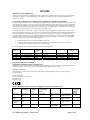
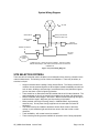
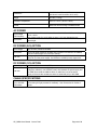
System Wiring Diagram
AP units
GPS sync & Ethernet
cables from each unit*
GPS antenna
GPS antenna
cable
optional
backhaul module
Network Connection
in
Cluster
Management
AP
Installation Kit
Module
300SS
AC or DC
power in
grounding
system
* Cables from only 1 sector are shown in diagram. There are 2 cables,
Ethernet and GPS sync, that would connect each sector unit to the AP
Installation kit.
Figure 4: System Wiring Diagram
SITE SELECTION CRITERIA
There are various issues that need to be taken into consideration when choosing a location for the
network infrastructure. The following is a list of those considerations. There may be others, as
each site is unique.
•
•
•
•
•
•
•
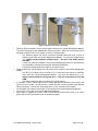
Height is essential when installing Canopy Access Points. The Canopy Access Point
modules must be mounted higher than other objects located immediately around them
such as trees, buildings, and tower legs, but at least 2 feet (0.6 m) below the highest
point on the tower or pole for lightning protection.
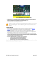
There should be no obstructions that will interfere with the unit’s internal antenna. The
area immediately in front of an Access Point module must be clear of all obstructions.
Will the installation area change in the future? Will there be structures high enough to
interfere with the signal? Will trees grow into the line-of-sight path?
When possible, avoid high RF energy sites (i.e. AM/FM stations, high powered
antennas, etc.) Do not place Canopy equipment in the same plane as other RF
equipment.
The means used by the installer to attach the Access Point cluster to the tower,
rooftop, or pole should be rigid and should not move or flex due to wind or other
vibrations.
Tower availability…will a tower have to be erected?
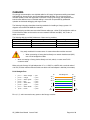
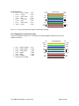
There must be grounding systems available for protection of the Canopy equipment.
AP_CMM2 User Manual Issue 4 Draft
Page 14 of 48