1
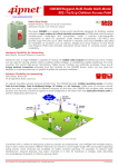
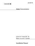
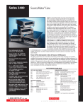
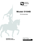
CanopyTM Backhaul Module
USER MANUAL
Part: 5700BH-UG-E
R 02 02
© 2002 Motorola, Inc. All rights reserved. Printed in the U.S.A
NOTICES
Federal Communications Commission (FCC) and Industry Canada (IC) Information:
This device complies with part 15 of the FCC Rules and Regulations and RSS-210 of Industry
Canada (IC). Operation is subject to the following two conditions: (1) This device may not cause
harmful interference, and (2) This device must accept any interference received, including
interference that may cause undesired operation. In Canada, users should be cautioned to take
note that high-powered radars are allocated as primary users (meaning they have priority) of 52505350 MHz and 5640-5850 MHz and these radars could cause interference and/or damage to
license-exempt local area network (LELAN).
This equipment has been tested and found to comply with the limits for a Class B digital device,
pursuant to Part 15 of the FCC Rules and RSS-210 of Industry Canada. These limits are designed
to provide reasonable protection against harmful interference in a residential installation. This
equipment generates, uses, and can radiate radio-frequency energy and, if not installed and used
in accordance with these instructions, may cause harmful interference to radio communications.
If this equipment does cause harmful interference to radio or television reception, which can be
determined by turning the equipment on and off, the user is encouraged to correct the interference
by one or more of the following measures:
• Increase the separation between the affected equipment and the unit;
• Connect the affected equipment to a power outlet on a different circuit from that which the
receiver is connected to;
• Consult the dealer and/or experienced radio/TV technician for help.
FCC ID: ABZ89FC4816
IC: 109W-5700
The term “IC:” before the radio certification number only signifies that Industry Canada
technical specifications were met.
Important Note:
Intentional or unintentional changes or modifications must not be made unless under the express
consent of the party responsible for compliance. Any such modifications could void the user’s
authority to operate the equipment and will void the manufacturer’s warranty. The Canopy
Backhaul (BH) must be installed to provide a separation distance of at least 20 cm (7.9 in) from all
persons. When adding the Canopy reflector dish, the reflector dish must be installed to provide a
separation distance of at least 1.5 m (59.1 in) from all persons and does not emit RF field in excess
of Health Canada limits for the general population; consult Safety Code 6, obtainable fro Health
Canada’s website http://www.hc-sc.gc.ca/rpb. Furthermore, it must not be co-located or operating
in conjunction with any other antenna or transmitter.
MOTOROLA, the stylized M Logo and all other trademarks indicated as such herein are
trademarks of Motorola, Inc. ® Reg. U.S. Pat & Tm. Office. Canopy is a trademark of Motorola,
Inc. All other product or service names are the property of their respective owners.
Motorola, Inc
Broadband Wireless Technology Center
50 East Commerce Drive
Schaumburg, IL 60173
http://www.motorola.com/canopy
Page 2
TABLE OF CONTENTS
GETTING STARTED ..............................................................................................4
Welcome .......................................................................................................................... 4
Features........................................................................................................................... 4
Warranty .......................................................................................................................... 4
PRODUCT DESCRIPTION.....................................................................................5
Canopy Backhaul............................................................................................................. 5
SITE PLANNING ....................................................................................................6
Site Selection Criteria ...................................................................................................... 6
Path Loss Considerations ................................................................................................ 6
GENERAL CONSIDERATIONS .............................................................................7
Frequency Planning ......................................................................................................... 7
Distance ........................................................................................................................... 7
Networking Information .................................................................................................... 7
Lightning Protection ......................................................................................................... 8
Electrical Requirements ................................................................................................... 8
INSTALLATION......................................................................................................9
Preparation ...................................................................................................................... 9
Installation Procedure ...................................................................................................... 9
WEB PAGE INFORMATION ................................................................................12
Home Page .................................................................................................................... 12
Status Page ................................................................................................................... 12
Configuration.................................................................................................................. 13
Event Log....................................................................................................................... 14
LUID Select.................................................................................................................... 14
Link Test ........................................................................................................................ 14
Time & Date ................................................................................................................... 14
Sessions ........................................................................................................................ 14
GPS Status .................................................................................................................... 15
Packet Status................................................................................................................. 15
SPECIFICATIONS................................................................................................16
Page 3
GETTING STARTED
WELCOME
Congratulations on the purchase of the Canopy Backhaul from Motorola! The Canopy Backhaul is
the latest innovation in high-speed wireless networking that lets you easily network at high speeds
with no wiring.
FEATURES
The following is a subset of features included with you Canopy Subscriber Module:
♦
♦
Network speeds of 10/100 BaseT and half/full duplex.
Small, compact design.
WARRANTY
Motorola offers a warranty covering a period of 90 days from the date of purchase by the retail
customer. If a product is found defective during the warranty period, Motorola will repair or replace
the product with the same or a similar model, which may be a reconditioned unit, without charge for
parts or labor.
IN NO EVENT SHALL MOTOROLA BE LIABLE TO YOU OR ANY OTHER PARTY FOR ANY
DIRECT, INDIRECT, GENERAL, SPECIAL, INCIDENTAL, CONSEQUENTIAL, EXEMPLARY OT
OTHER DAMAGE ARISING OUT OF THE USE OR INABILITY TO USE THE PRODUCT
(INCLUDING, WITHOUT LIMITATION, DAMAGES FOR LOSS OF BUSINESS PROFITS,
BUSINESS INTERRUPTION, LOSS OF BUSINESS INFORMATION OR ANY OTHER
PECUNIARY LOSS0, OR FROM ANY BREACH OF WARRANTY, EVEN IF MOTOROLA HAS
BEEN ADVISED OF THE POSSIBILITY OF SUCH DAMAGES. (Some states do not allow the
exclusion or limitation of incidental or consequential damages, so the above exclusion or limitation
may not apply to you.) IN NO CASE SHALL MOTOROLA’S LIABILITY EXCEED THE AMOUNT
YOU PAID FOR THE PRODUCT.
Page 4
PRODUCT DESCRIPTION
Canopy Backhaul
The base cover of your Canopy Backhaul is easily removed by depressing the release lever on the
back of the cover.
Base Cover
Base Cover
Release
Ethernet
Lever
Cable
FIGURE 1
Remove the base cover as shown in FIGURE 1 to access the Ethernet connection and the
Connection LED alignment indicators.
♦
The RJ-45 connector is used to attach the Ethernet cable
♦
The RJ-11 connector is used to attach the GPS sync cable
♦
The LED’s indicate system status and are used for alignment.
Canopy BH
RJ11
Connector
RJ45
Connector
Connection
LEDs
Base Cover
Ethernet
Cable
FIGURE 2
Page 5
SITE PLANNING
SITE SELECTION CRITERIA
• Height is essential when installing a Canopy Backhaul. The Canopy Backhaul should be
mounted higher than other objects located immediately around it such as trees, buildings, etc.
The Canopy Backhaul units that make up one point-to-point link must have a clear,
unobstructed view or each other.
• There should be no obstructions that will interfere with the unit’s internal antenna. The area
immediately in front of a Backhaul must be clear of all obstructions.
• When possible, avoid high RF energy sites. Do not place Canopy equipment in the same
plane as other RF equipment.
• The means used by the installer to attach the Backhaul to the tower or pole should be rigid
and should not move or flex due to wind or other vibrations.
PATH LOSS CONSIDERATIONS
•
Fresnel Loss - The Fresnel Zone is a theoretical area around the line of sight of an antenna
transmission that can affect the signal strength. Objects that penetrate the Fresnel Zone can
cause fading of the transmitted signal. This fading is caused by the cancellation of the signal
due to out-of-phase reflections. An unobstructed line of sight is important, but it is not the
only determination of an adequate placement. Even though the path has a clear line of
sight, if obstructions (such as terrain, vegetation, metal roofs, cars, etc.) penetrate the
Fresnel zone, there will be signal loss. FIGURE 2 illustrates a Fresnel zone.
Fresnel Zone
D1
D2
Transmitter
Receiver
FIGURE 2
•
•
•
Free Space Path Loss – As an RF signal travels through space, it is attenuated by the
distance from the initial transmission point. The farther away from the transmission point,
the weaker the RF signal.
Foliage Loss – Tree and plant foliage will cause additional signal loss. Seasonal density,
moisture content of the foliage, and other factors such as wind may change the amount of
loss. Caution should be used when a link may transmit though this type of environment.
Carrier to Interference – ratio of received signal from a desired source to an interfering
signal.
Page 6
GENERAL CONSIDERATIONS
The Canopy Backhaul units are configured as a pair with one of the units designated as the
Timing-Master and the other unit is designated as the Timing-Slave. If the Backhaul units are
being used in conjuction with the Canopy Access Point Installation Kit, then the units must be
confiured to “Sync to Received Signal.” This parameter is set through the Configuration webpage.
FREQUENCY PLANNING
The Canopy Backhaul utilized the frequency band of 5.725 GHz – 5.825 GHz. There are 4 usable
channels within the Canopy system.
DISTANCE
The Canopy Backhaul system can create a point-to-point link within the following distances:
Configuration
Distance
Both ends of the link utilizing the internal
Backhaul antennas
2 miles
One end of the link utilizing a Canopy passive
reflector
10 miles
Both ends of the link utilizing Canopy passive
reflectors
20 miles
NETWORKING INFORMATION
Default IP Address
Each Canopy Backhaul unit comes configured with the default IP address of 169.254.1.1.
Setting Default IP Address
If you have programmed a unit and have forgotten the IP address, use the following procedure to
restore the unit to the default address of 169.254.1.1.
• Using a small length of CAT 5 cable and a 6 conductor RJ-11 connector, connect pins 4
and 6 by soldering them together.
• Before powering-up the Access Point unit, place the “default plug” into the RJ11 port of
the unit.
• Power-up the unit normally.
• The default plug will program the unit to use the 169.254.1.1 IP address, but will not
affect any of the other configurations stored in the unit.
Page 7
LIGHTNING PROTECTION
• Canopy Backhaul must be mounted at least 2 feet below the highest point at the site.
• Ensure the location is properly grounded for lightning protection according to the NEC and
applicable local codes.
• The Canopy Surge Suppressor must be used to protect from electrical surges along the
Ethernet cables.
ELECTRICAL REQUIREMENTS
•
•
Specifications for the voltages and distance can be found in the Specification section of this
manual.
Make certain the installation conforms to the National Electrical Code (NEC) and local
codes. If uncertain of code requirements, obtain the services of a licensed electrician.
Page 8
INSTALLATION
The Canopy Backhaul unit can be mounted in a variety of ways depending on the layout of the
installation site.
PREPARATION
Cable Preparation
• Determine length of cables needed for Ethernet and GPS sync.
• Use Canopy approved cables that are ultraviolet (UV) and outdoor rated.
INSTALLATION PROCEDURE
•
•
•
•
Remove the base cover from all Canopy Backhaul Modules to be installed
Remove the GPS sync cable knockout from the base cover with needle-nose pliers
Mount the Canopy Backhaul units
Route the Ethernet cables from the Canopy Backhaul Modules to the Canopy Cluster
Management Module.
o The Ethernet cables use RJ-45 connectors (standard Ethernet) that connect to
matching ports within the Canopy Cluster Management Module.
o A total of 8 ports are available on the Canopy Cluster Management Module, to
accommodate 6 Canopy Access Point Modules and 2 Canopy Backhaul Modules.
• Route the GPS sync (serial) cables from the Canopy Backhaul Modules, if necessary, to the
Canopy Cluster Management Module.
o The GPS sync cables use RJ-11 connectors that connect to matching ports within
the Canopy Cluster Management Module.
o A total of 8 ports are available on the Canopy Cluster Management Module, to
accommodate 6 Access Point Canopy Modules and 2 Canopy Backhaul Modules.
• Verify that all of the Canopy Backhaul units are reliably connected to the Ethernet switch by
observing that the port indicator LEDs on the Ethernet switch are lit.
• If installing Canopy Backhaul Modules independently of the Canopy Cluster Management
Module, proper grounding of the Ethernet cable is necessary. The Canopy Surge
Suppressor is such a device for this situation.
• Connect computer to Timing-Slave unit to observe the Radio Signal Strength Indicator (RSSI)
and Jitter values with aligning the ends of the link.
Initial Timing-Master and Timing-Slave Alignment
•
•
If the Backhauls Modules are not utilizing passive reflectors, then visually align the units.
If the Backhauls Modules are utilizing passive reflectors then visually align if possible or
utilize compass headings and initiate step 1 in the following process:
1. Lock down Timing-Master unit
2. Slowly move Timing-Slave unit to obtain signal from the Timing-Master.
3. Monitor the Status webpage at the Timing-Slave while implementing Step 2.
a. Watch for “Syncing”, then “Registering”, then “Registered”. When the unit is
registered, move on to Step 4.
4. While monitoring RSSI and Jitter, at the Timing-Slave incrementally move the unit in
the vertical plane. Observe where the values are at their best and lock down the unit.
Now, incrementally move the unit in the horizontal plane. Observe where the values
are at their best and lock down the unit. Alignment is complete when reported values
are at their best and the unit is registered.
5. If necessary incrementally move the Timing-Master unit a couple (2-3) degrees and go
to Step 1.
Page 9
CABLING
The following information describes the wiring standards for installing a Canopy system. All
diagrams utilize the EIA/TIA 568B color standard.
RJ-45 Straight-Thru:
pin 1 →
pin 2 →
pin 3 →
pin 4 →
pin 5 →
pin 6 →
pin 7 →
pin 8 →
!
!
!
!
!
!
!
!
white / orange
orange
white / green
blue
white / blue
green
white / brown
brown
← pin 1
← pin 2
← pin 3
← pin 4
← pin 5
← pin 6
← pin 7
← pin 8
Where pins 4, 5, 7, and 8 are used to carry power to the Canopy modules.
RJ-45 Straight-Thru
Pin
Pin
TX+ 1
1 RX+
TX- 2
2 RX-
RX+ 3
3 TX+
-24 VDC
4
4
5
5
RX- 6
+24 VDC
-24 VDC
6 TX-
7
7
8
8
+24 VDC
RJ-45 Crossover:
!
!
!
!
!
!
!
!
pin 1 →
pin 2 →
pin 3 →
pin 4 →
pin 5 →
pin 6 →
pin 7 →
pin 8 →
white / orange
orange
white / green
blue
white / blue
green
white / brown
brown
← pin 3
← pin 6
← pin 1
← pin 4
← pin 5
← pin 2
← pin 7
← pin 8
Where pins 4, 5, 7, and 8 are used to carry power to the Canopy modules.
Pin
RJ-45 Crossover
Pin
TX+ 1
3 RX+
TX- 2
6 RX-
RX+ 3
1 TX+
-24 VDC
4
4
5
5
RX- 6
+24 VDC
-24 VDC
2 TX-
7
7
8
8
+24 VDC
Page 10
RJ-11 Straight-Thru (for GPS sync cable):
Utilizing CAT 5 cable and 6-pin RJ-11 connectors, the following diagram shows the wiring of the
cable for GPS sync.
pin 1 → white / orange
pin 2 → white / green
pin 3 → white / blue
pin 4 → green
pin 5 → blue
pin 6 → orange
pin 7 & 8 → not used
!
!
!
!
!
!
!
Pin
1-pps 1
RJ-11 Straight-Thru
← pin 1
← pin 2
← pin 3
← pin 4
← pin 5
← pin 6
Pin
1 1-pps
TX+ 2
2 TX+
RX+ 3
3 RX+
not
used
4
4
5
5
not
used
gnd 6
6 gnd
not
used
not
used
Page 11
WEB PAGE INFORMATION
Web pages are available for each Canopy unit. These pages are used to configure the unit and to
evaluate its performance. Access the web pages by entering the IP address for a Canopy product
into a standard web browser. Descriptions of these pages are provided on the following pages.
•
•
•
•
•
•
•
•
•
•
Home
Status
Configuration
Event Log
LUID Select
Link Test
Time & Date
Sessions
GPS Status
Packet Status
HOME PAGE
The Home page contains a welcome message for the product. There are no configurable items on
this page.
STATUS PAGE
The Status page contains information on the operation of the product. It is the default webpage.
The following parameters are displayed.
PARAMETERS
Device Type
Software Version
FPGA Version
Device ESN
Uptime
System Time
Data Slots Up
Data Slots Down
Registered SM Count
Ethernet Interface
DESCRIPTION
Describes the configuration that the unit has been set to.
Displays the version of software currently loaded into the unit.
Displays the version of the FPGA (field programmable gate array)
currently loaded into the unit.
Displays the Electronic Serial Number of the unit.
Displays the length of time the unit has been operating since power
was applied.
Displays the time that is received from the connected GPS unit. If
there is no GPS, the system time is set on the “Time & Date”
Webpage.
This information is used only by the Canopy team.
This information is used only by the Canopy team.
Displays the current count of subscriber modules registered to the
access point.
Displays the configuration of the Ethernet Interface. The interface
can be either 10 or 100 BaseT and either half or full duplex.
Page 12
CONFIGURATION
This page contains information and configurable parameters that change the operation of the
product.
PARAMETER
Sync Input
RF Frequency Carrier
Downlink Data
Hi Priority Uplink
Percentage
Total NumUAckSlots
Uacks Reserved High
NumDAcksSlots
Dacks Reserved High
NumCtlSlots
NumCtlSlots Reserved
High
Uplink Bandwidth Cap
Dwnlink Bandwidth Cap
Lan IP
Lan Subnet Mask
Default Gateway
Private IP
Private IP Subnet Mask
Color Code
Sector ID
Max Range
Webpage Auto Update
Display Only Access
Full Access
Community String
Accessing Subnet
Trap Address
DESCRIPTION
Toggles the Backhaul from generating its own timing sync pulse to
receiving a sync pulse from an external GPS source. The default
value is for the unit to generate its own timing sync pulse.
Use this to set the frequency the Backhaul will function on.
Determines the division of total bandwidth between downstream and
the upstream. The default value is 75%.
This information is used only by the Canopy team.
This information is used only by the Canopy team.
This information is used only by the Canopy team.
This information is used only by the Canopy team.
This information is used only by the Canopy team.
This information is used only by the Canopy team.
This information is used only by the Canopy team.
Determines the upstream bandwidth limit, measured in Kbps. The
default value is 9999.
Determines the downstream bandwidth limit, measured in Kbps. The
default value is 9999.
Determines the IP address of the Backhaul through the Ethernet
cable. The default value is 169.254.1.1
Determines the subnet mask for the Backhaul. The default value is
255.255.0.0
Determines the default gateway for the Backhaul. The default value
is 169.254.0.0
Determines the IP address of the RF link.
Determines the subnet mask of the RF link
This parameter will determine what unit the Backhaul will register on.
Two units must have the same color code for registration to occur.
The range for this parameter is 0 to 254. The default value is 0.
Displays a number that is sent to all registered units. The range of
this parameter is 0 to 15. The default value is 0.
This information is used only by the Canopy team.
Determines how often the webpages will refresh automatically. The
measurement is in seconds. The default value is 0, which will never
refresh the webpages.
Enter a password to make the status of the pages Display Only. The
default value is no password.
Enter a password to allow full access (view and change) to the
webpages. The default value is to have no value.
Determines the community access for SNMP reporting.
Determine what subnets can send SNMP information.
Determines the IP address of the unit where SNMP trap information
will be transmitted.
Page 13
EVENT LOG
This page contains information that is recorded from the subscriber module for troubleshooting
purposes. Click the “Clear Event Log” button to clear the log.
LUID SELECT
This webpage connects to a registered unit over the RF link, to view its internal webpages. The
Sessions webpage determines which LUID corresponds to a specific unit. Enter the LUID in the
field displayed and then click “Change LUID” to set the parameter. Click “View Current Subscriber
Modem” to access the unit with that LUID.
LINK TEST
This webpage has a test for measuring the throughput and efficiency of the RF link. Enter a
number into the field labeled “Duration” to choose the duration of the test. This value is measured
in seconds. To start the link test, click the “Start Test” button. The test will run for the set duration.
If the webpage is not set to automatically refresh, click the “Refresh Display” button to display the
results.
The key fields are:
• Downlink RATE, bits per second
• Uplink RATE, bits per second
• Downlink Efficiency, percent
• Uplink Efficiency, percent
TIME & DATE
Set the system time and date from this webpage for a Backhaul Module not using GPS.
SESSIONS
This webpage displays what Backhaul Timing-Slaves have registered with the Backhaul TimingMaster. The following are the parameters and their descriptions.
PARAMETER
LUID
MAC
STATE
Session Timeout
Air Delay
Used
Session Count
Reg Count
Re-Reg Count
Average RSSI
Last RSSI
Average Jitter
Last Jitter
DESCRIPTION
Displays the logical unit ID for the specific unit.
Displays the layer 2 address for the specific unit.
Displays the current state (idle or in session) for the specific unit.
This information is used only by the Canopy team.
Displays the distance.
This information is used only by the Canopy team.
Displays the number of sessions
This information is used only by the Canopy team.
This information is used only by the Canopy team.
Displays the average RSSI value
Displays the last known RSSI value
Displays the average Jitter value
Displays the last known Jitter value
Page 14
GPS STATUS
This webpage displays information from the GPS module located in the Canopy Cluster
Management Module.
PACKET STATUS
This webpage displays TCP throughput and error information for the Ethernet connection of the
Backhaul Module.
Page 15
SPECIFICATIONS
Operating Frequency Range
U-NII Mid band
5.725 to 5.825 GHz
Access Method
TDD/TDMA
Signaling Rate
10 Mbps
Modulation Type
High Index BFSK
(Optimized for interference rejection)
Carrier to Interference (C/I)
also known as Jitter
3dB 10-4 BER @ -65 dBm
Receiver Sensitivity
-83dBm 10-4 BER
Operating Range
(All Weather)
Up to 2 miles with integrated antenna. Up to 20 miles with
installed passive reflectors.
Transmitter Power
Meets FCC UNII ERP Limit
DC Power
24 VDC @ 0.3 Amp (active state)
Interface
10/100 BaseT, half/full duplex
Rate auto negotiated (802.3 compliant)
Protocols Used by Canopy
IPV4, UDP, TCP, ICMP, Telnet,
HTTP, FTP, SNMP
Protocols Supported by
Canopy
Switched Layer 2 Transport with support for all common Ethernet
protocols including IPV6, NetBIOS, DHCP, IPX, etc.
Software Upgrade Path
Remotely downloaded into FLASH via RF link
Network Management
HTTP, TELNET, FTP, SNMP
Wind
190 km/hr (118 miles/hr)
Temperature
-40°C to +55°C (-40ºF - +131ºF)
Dimensions
11.75” H x 3.4” W x 3.4” D (29.9 cm H x 8.6 cm W x 8.6 cm D)
Weight
1 lb. (.45kg)
with passive reflector
6.5 lbs. (3 kg)
Page 16