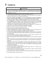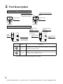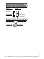
1
Amplifier Built-in Ultra-compact Type Photoelectric Sensor EX-20 Series USER’S MANUAL WUME-EX20-3 Phone: 800.894.0412 - Fax: 888.723.4773 - Web: www.clrwtr.com - Email: [email protected] Contens 1. Cautions ··························································································3 2. Part Description ················································································4 3. Mounting ·························································································6 3-1 Mounting the sensor ··············································································· 6 3-2 Mounting to sensor mounting bracket (Optional) ··········································· 7 3-3 Mounting to mounting spacer (Optional) (Front sensing type) ·························· 8 3-4 Installation interval ················································································ 9 3-5 ) ··13 4. I/O Circuit Diagram ·········································································· 14 5. Adjustment ····················································································· 15 5-1 Beam alignment (Thru-beam type / ) ··15 5-2 , ! " ) ····························································16 6. Stability Indicator ············································································· 18 7. Option ··························································································· 19 7-1 Slit mask (Thru-beam type / ) ·············································19 #"$%) ································20 &'* ················································································· 21 9. Dimensions ···················································································· 24 2 Phone: 800.894.0412 - Fax: 888.723.4773 - Web: www.clrwtr.com - Email: [email protected] 1. Cautions WARNING + Never use this product as a sensing device for personnel protection. + In case of using devices for personnel protection, use products which meet laws and standards, such as OSHA, ANSI or IEC etc., for personnel protection applicable in each region or country. + This product has been developed / produced for industrial use only. + The thin cable (0.1mm2) is used for this product. Thus, take care that if the cable is pulled with excessive force, it may cause cable break. + Convergent reflective type EX-24: ' ; there is a reflective object (conveyor, etc.) in the background, since it may affect the <=<' + If a reflective object is present in the background, the sensing of narrow-view reflective type EX-28:<'>=* <';<= <<=' + If sensors are mounted close together and the ambient temperature is near the maximum rated value, provide for enough heat radiation / ventilation. + Make sure to carry out wiring in the power supply OFF condition. + Take care that wrong wiring will damage the sensor. + Verify that the supply voltage variation is within the rating. + If power is supplied from a commercial switching regulator, ensure that the frame ground (F.G.) terminal of the power supply is connected to an actual ground. + In case noise generating equipment (switching regulator, inverter motor, etc.) is used in the vicinity of this product, connect the frame ground (F.G.) terminal of the equipment to an actual ground. + Do not run the wires together with high-voltage lines or power lines or put them in the same raceway. This can cause malfunction due to induction. + Do not use during the initial transient time (50ms) after the power supply is switched ON. + ?=@" lamp, a high frequency lighting device or sunlight etc., as it may affect the sensing performance. + Extension up to total 50m (each emitter and receiver of thru-beam type), or less, is possible with 0.3mm2, or more of conductor area cable. However,the extension of a power supply line and the output line of less than 10m is acceptable in case using this product as conforming to S-mark. + This sensor is suitable for indoor use only. + Do not use this sensor in places having excessive vapor, dust, etc., or where it may come in contact with corrosive gas, etc. + Take care that the sensor does not come in contact with oil, grease, organic solvents such as thinner, etc., strong acid, or alkaline. + ?<<@' + Never disassemble or modify the sensor. 3 Phone: 800.894.0412 - Fax: 888.723.4773 - Web: www.clrwtr.com - Email: [email protected] 2. Part Description Stability indicator (Green) Lights up under stable light received condition or stable dark condition. Operation indicator (Orange) Lights up when the output is ON. Beam-emitting part Beam-receiving part <Emitter> <Receiver> ! Stability indicator (Green) Lights up under stable light received condition or stable dark condition. Beamemitting part Sensitivity adjuster Sensing range increases when turned clockwise. <Emitter> Operation mode switch Operation indicator (Orange) Lights up when the output is ON. Beam-receiving part Operation mode switch <Receiver> Operation Description Light-ON Light-ON mode is obtained when the operation mode switch is turned fully clockwise (L side). Dark-ON Dark-ON mode is obtained when the operation mode switch is turned fully counterclockwise (D side). Note: Use the accessory adjusting screwdriver to turn the operation mode switch slowly. Turning with excessive strength will cause damage to the adjuster. 4 Phone: 800.894.0412 - Fax: 888.723.4773 - Web: www.clrwtr.com - Email: [email protected] "#$%! &''#$%! (%#$%! )*%*#$%! Stability indicator (Green) Lights up under stable light received condition or stable dark condition. Operation indicator (Orange) Lights up when the output is ON. Beam-receiving part Beam-emitting part Sensitivity adjuster Sensing range increases when turned clockwise. (%#$%+ Stability indicator (Green) Lights up under stable light received condition or stable dark condition. Beam-receiving part Operation indicator (Orange) Lights up when the output is ON. Beam-emitting part 5 Phone: 800.894.0412 - Fax: 888.723.4773 - Web: www.clrwtr.com - Email: [email protected] 3. Mounting 3-1 Mounting the sensor + Mount using M3 screws. The tightening torque should be 0.5N·m or less. Front sensing type M3 pan head screws (Note) Side sensing type M3 screws !K >Q ' 6 Phone: 800.894.0412 - Fax: 888.723.4773 - Web: www.clrwtr.com - Email: [email protected] 3-2 Mounting to sensor mounting bracket (Optional) Sensor mounting brackets (optional) are available. In case the sensor is mounted on a sensor mounting bracket the tightening torque should be 0.5N·m or less. Sensor mounting bracket for front sensing type MS-EX20-1 MS-EX20-3 Material: Stainless steel (SUS304) Two M3 (length 5mm) pan head screws [stainless steel (SUS304)] are attached. Material: Stainless steel (SUS304) Two M3 (length 5mm) pan head screws [stainless steel (SUS304)] are attached. Sensor mounting bracket for side sensing type MS-EX20-2 Material: Stainless steel (SUS304) Two M3 (length 14mm) screws with washers [stainless steel (SUS304)] are attached. MS-EX20-4 Material: Stainless steel (SUS304) Two M3 (length 14mm) screws with washers [stainless steel (SUS304)] are attached. MS-EX20-5 Swivel: 360° rotation Material: Die-cast zinc alloy Height adjustment: Approx. 15mm Material: Nylon 6 Two M3 (length 12mm) screws with washers [stainless steel (SUS304)], one M3 (length 10mm) hexagon-socket-head bolt [stainless steel (SUS304)], one M3 hexagon nut [stainless steel (SUS304)] are attached. 7 Phone: 800.894.0412 - Fax: 888.723.4773 - Web: www.clrwtr.com - Email: [email protected] 3-3 Mounting to mounting spacer (Optional) (Front sensing type) + > <= MS-EX20-FS*@ ' Mounting method 1. Fit the mounting spacer on the sensor. Mounting spacer MS-EX20-FS (Optional) 2. Align the mounting holes of the mounting spacer and the sensor and mount with M3 screws. The tightening torque should be 0.5N·m or less. M3 screws 8 Phone: 800.894.0412 - Fax: 888.723.4773 - Web: www.clrwtr.com - Email: [email protected] 3-4 Installation interval + This product does not incorporate auto interference prevention function. In case aligning 2 of this sensors closely, follow diagrams below. (typical) + RWX' <$YW' Setting distance L (mm) Parallel deviation diagram (typical) of Thru-beam type EX-21: 1 (L1) 0.5 WZ\ 0 100 50 0 50 6799%9': In case using at sensing distance (L1) 1m, the opWZ\@'^_'$ diagram. The installation interval is Approx. 59.2mm × 2 = approx. 118.4mm Thus, install EX-21: @' ZZ&'{ away. 100 Left Center Right W\ Setting distance L (mm) Parallel deviation diagram (typical) of Thru-beam type EX-23: 2 (L2) 1 W$\ 0 100 50 0 50 6799%9': In case using at sensing distance (L2) 2m, the opW$\@'||'_ diagram. The installation interval is Approx. 66.9mm × 2 = approx. 133.8mm Thus, install EX-23: @' ZQQ'& away. 100 Left Center Right W\ EX-21:K}@'ZZ&'{ EX-23:K}@'ZQQ'& EX-21:K}@'ZZ&'{ EX-23:K}@'ZQQ'& EX-21:KZ EX-23:K$ 9 Phone: 800.894.0412 - Fax: 888.723.4773 - Web: www.clrwtr.com - Email: [email protected] Setting distance L (mm) =999!%!/$95'"#$%: 200 (L3) 100 WQ\ 0 20 10 0 10 6799%9': In case using at sensing distance (L3) 200mm, the WQ\@'_'# left diagram. The installation interval is Approx. 9.7mm × 2 = approx. 19.4mm Thus, install EX-29: @' Z_'{ away. 20 Left Center Right W\ "#$% EX-29:K}@'Z_'{ EX-29:K}@'Z_'{ EX-29:K$ 10 Phone: 800.894.0412 - Fax: 888.723.4773 - Web: www.clrwtr.com - Email: [email protected] @9!!/$95'"#$%: Setting distance L (mm) 200 W{\ 150 (L4) 100 50 6799%9': In case using at sensing distance (L4) 120mm, the W{\@'Q'$ left diagram. The installation interval is Approx. 3.02mm × 2 = approx. 6.04mm Thus, install EX-22: @' |'{ away. 0 4 2 0 2 4 Left Center Right W\ @9!!B9!$/$95'(%#$%+: Setting distance L (mm) 40 30 20 (L5) 10 W^\ 6799%9'+: In case using at sensing distance (L5) 19mm, the W^\@'Z'_$ left diagram. The installation interval is Approx. 1.92mm × 2 = approx. 3.84mm Thus, install EX-24: @' Q'&{ away. 0 4 2 0 2 4 Left Center Right W\ @9!!B9!$/$95'(%#$% : Setting distance L (mm) 20 15 10 (L6) 5 W|\ 6799%9' : In case using at sensing distance (L6) 8mm, the opW|\@''ZZ diagram. The installation interval is Approx. 0.11mm × 2 = approx. 0.22mm Thus, install EX-26: @' '$$ away. 0 1 0.5 0 0.5 1 Left Center Right W\ 11 Phone: 800.894.0412 - Fax: 888.723.4773 - Web: www.clrwtr.com - Email: [email protected] @9!!/$95')*%*#$%: Setting distance L (mm) 200 W#\ 150 100 (L7) 50 6799%9': In case using at sensing distance (L7) 70mm, the W#\@''#{ left diagram. The installation interval is Approx. 0.74mm × 2 = approx. 1.48mm Thus, install EX-28: @' Z'{& away. 0 4 2 0 2 4 Left Center Right W\ &''#$%H(%#$%+ )*%*#$% Model No. EX-22: EX-24: EX-26: EX-28: B B A 120mm 19mm 8mm 70mm B Approx. 6.04mm or more Approx. 3.84mm or more Approx. 0.22mm or more Approx. 1.48mm or more A 12 Phone: 800.894.0412 - Fax: 888.723.4773 - Web: www.clrwtr.com - Email: [email protected] 3-5 Mounting when detecting materials having a gloss /"#$%5 + Please take care of the following points when detecting materials having a gloss with EX-29:' 1. =X *'Z\ 2. Install at an angle of 10 to 30 degrees to the sensing object. L Sensing object =X* 10 to 30° ZK Glossy surface ;< <<' 13 Phone: 800.894.0412 - Fax: 888.723.4773 - Web: www.clrwtr.com - Email: [email protected] 4. I/O Circuit Diagram )=)!=)=$Q Color code Main circuit (Brown) +V + - 12 to 24V DC ±10% (Blue) 0V Internal circuit Users’ circuit )=)Q$%H"#$% &''#$%H(%#$%+ )*%*#$% Color code (Brown) +V Main circuit Load + (Black) Output 50mA max. - 12 to 24V DC ±10% (Blue) 0V Internal circuit Users’ circuit =)=Q$%=)=)H"#$%=) &''#$%=)H(%#$%+=) =) )*%*#$%=) Color code Main circuit (Brown) +V 50mA max. (Black) Output + - 12 to 24V DC ±10% Load (Blue) 0V 14 Internal circuit Users’ circuit Phone: 800.894.0412 - Fax: 888.723.4773 - Web: www.clrwtr.com - Email: [email protected] 5. Adjustment 5-1 Beam alignment /H"#$%5 1. In case of EX-23: to the Light-ON mode position (L side). 2. Placing the emitter and the receiver face to face along a straight line, move the emitter in the up, down, left and right directions, in order to determine the range of the light received condition with the help of the operation indicator (orange). Then, set the emitter at the center of this range. 3. Similarly, adjust for up, down, left and right angular movement of the emitter. 4. Further, perform the angular adjustment for the receiver also. 5. Check that the stability indicator (green) lights up. 6. In case of EX-23: Light-ON or Dark-ON, as per your requirement, with the operation mode switch. Sensing object Operation indicator (Orange) Emitter Receiver Stability indicator (Green) Emitter Receiver "#$% 1. Turn the sensitivity adjuster fully clockwise to the maximum sensitivity position (MAX). 2. along a straight line, move the reflector in the up, down, left and right directions, in order to determine the range of the light received condition with the help of the operation indicator (orange). ?' 3. Similarly, adjust for up, down, left and right angu' 4. Further, perform the angular adjustment for the sensor also. 5. Check that the stability indicator (green) lights up. Sensing object Operation indicator (Orange) Sensor Stability indicator (Green) Sensor 15 Phone: 800.894.0412 - Fax: 888.723.4773 - Web: www.clrwtr.com - Email: [email protected] 5-2 Sensitivity adjustment &''#$%H(%#$% )*%*#$% Sensitivity adjuster Step 1. Turn the sensitivity adjuster fully counterclockwise to the =\' 2. In the light received condition, turn the sensitivity adjuster = *A where the sensor enters the “Light” state operation. A 3. In the dark condition, turn the sensitivity adjuster further clockwise until the sensor enters the “Light” state operation and then bring it back to confirm point B where the sensor just returns to the “Dark” state operation. If the sensor does not enter the “Light” state operation even when the sensitivity adjuster is turned fully clockwise, the position is point B. B A 4. The position at the middle of points A and B is the optimum sensing position. B Optimum position A Notes: 1) Use the accessory adjusting screwdriver to turn the adjuster slowly. Turning with excessive strength will damage the adjuster. 2) In case of using EX-22:^= range becomes extremely narrow. 16 Phone: 800.894.0412 - Fax: 888.723.4773 - Web: www.clrwtr.com - Email: [email protected] <Reference> Light received condition Emitter Receiver Dark condition Emitter Receiver Thru-beam type Sensing object Sensor Sensor Sensing object Sensor Sensing object Sensor Sensor Sensing object Sensor ! " Relation between output and indicators In case of Light-ON Stability indicator (Green) Operation indicator (Orange) In case of Dark-ON Output Lights up Lights up ON Turns OFF Turns OFF Lights up OFF Sensing condition Stable light receiving Unstable light receiving Unstable dark receiving Stable dark receiving Output Operation indicator (Orange) OFF Turns OFF Stability indicator (Green) Lights up Turns OFF ON Lights up Lights up 17 Phone: 800.894.0412 - Fax: 888.723.4773 - Web: www.clrwtr.com - Email: [email protected] 6. Stability Indicator + The stability indicator (green) lights up when the incident light intensity has sufficient margin with respect to the operation level. Incident light intensity level is such that the stability indicator light up, stable sensing can be done without the light received operation and the light interrupted operation being affected by a change in ambient temperature or supply voltage. Operation of stability indicator Light interruption margin Light received operation 100 0 Setting distance Incident light intensity (%) Output operation level Approx. 15% Approx. 25% Light interrupted operation Incident light margin Light up Light OFF Light up Output operation 0 18 Phone: 800.894.0412 - Fax: 888.723.4773 - Web: www.clrwtr.com - Email: [email protected] 7. Option U9V/5 + >=YZ, the sensor can detect a small object. However, the sensing range is reduced when the slit mask is mounted. Type Round slit mask Rectangular slit mask Model No. Slit mask Slit size OS-EX20-05 Slit size EX21: Sensing distance Min. sensing object Slit on one side Slit on both side Slit on one side Slit on both side 200mm 40mm ø2.6mm ø0.5mm 350mm 70mm ø3mm ø0.5mm 600mm 300mm ø2.6mm 0.5 × 3mm 800mm 400mm ø3mm 0.5 × 3mm ø0.5mm OS-EX20E-05 EX-23: OX-EX20-05×3 EX-21: 0.5 × 3mm OX-EX20E-05×3 EX-23: + The slit mask should be mounted on the product before mounting the sensor. Mounting method 1. = *' ! Slit mask OS-EX20-: (Optional) Slit mask OS-EX20E-: (Optional) 2. Align the mounting holes of the slit mask and the sensor and mount with two M3 screws [in case of EX-21:Q ' The tightening torque should be 0.5N·m or less. ! M3 screws M3 screws 19 Phone: 800.894.0412 - Fax: 888.723.4773 - Web: www.clrwtr.com - Email: [email protected] U"#$'$% /"#$%5 + RF-200 EX-29:' (we also offer them without refractor RF-200) + ;' Designation Model No. Sensor Installation distance A B Sensing distance Min. sensing object RF-200 EX-29: (Accessory) 30mm 200mm 30 to 200mm ø15mm RF-210 EX-29: (Optional) 50mm 400mm 50 to 400mm ø30mm RF-11 EX-29: (Optional) 70mm 200mm 70 to 200mm ø15mm RF-12 EX-29: (Optional) 60mm 280mm 60 to 280mm ø15mm tape < in this range Sensor Actual sensing range of the sensor Installation distance (A) * >YY\K 9.6mm × 25.25mm × 8mm Thru-hole threads: ø3.2mm >YY\K 33.3mm × 12.8mm × 11mm Thru-hole threads: ø3.4mm >YY\K 30mm × 8mm × 0.7mm Ambient temperature: -25 to +50ºC Ambient humidity 35 to 85% RH >YY\K 30mm × 25mm × 0.7mm Ambient temperature: -25 to +50ºC Ambient humidity 35 to 85% RH Installation distance (B) 20 Phone: 800.894.0412 - Fax: 888.723.4773 - Web: www.clrwtr.com - Email: [email protected] 8. $@$ Thru-beam Type Model No. Light-ON (Note 2) Dark-ON Front sensing Side sensing Side sensing EX-21A EX-23 (Note 3) EX-29A EX-21B EX-29B Sensing range 1m 2m 30 to 200mm (Note 4) Sensing object Min. ø2.6mm opaque object Setting distance between emitter and receiver: 1m Min. ø3mm opaque object Setting distance between emitter and receiver: 2m ø15mm or more opaque or translucent object (Note 4, 6) - Hysteresis Repeatability perpendicular to sensing axis 0.05mm or less Supply voltage Current consumption 0.5mm or less 12 to 24V DC±10% Ripple P-P 10% or less Emitter: 10mA or less, Receiver: 10mA orless <NPN output type> NPN open-collector transistor Maximum sink current: 50mA Applied voltage: 30V DC or less (between output and 0V) Residual voltage: 2V or less (at 50mA sink current) 1V or less (at 16mA sink current) Output Short-circuit protection Incorporated Response time 0.5ms or less Protection IP67 (IEC) Ambient temperature -25 to +55°C (No dew condensation or icing allowed), Storage: -30 to +70°C Ambient humidity 35 to 85% RH, Storage: 35 to 85% RH Emitting element Red LED (modulated) Material Enclosure: Polyethylene terephthalate, Lens: Polyalylate 0.1mm2 3-core (thru-beam type sensor emitter: 2-core) cabtyre cable, 2m long Cable > 13mA or less <PNP output type> PNP open-collector transistor Maximum source current: 50mA Applied voltage: 30V DC or less (between output and +V) Residual voltage: 2V or less (at 50mA source current) 1V or less (at 16mA source current) Net weight Emitter, receiver: Approx. 20g each Approx. 20g Gross weight Approx. 50g Approx. 30g Accessories - Adjusting screwdriver: 1 pc. RF-200 \KZ' Adjusting screwdriver: 1 pc. 21 Phone: 800.894.0412 - Fax: 888.723.4773 - Web: www.clrwtr.com - Email: [email protected] Type Model No. Light-ON (Note 2) Dark-ON Sensing range Sensing object Small spot beam type Long distance spot beam type Side sensing Front sensing Side sensing Side sensing EX-22A EX-24A EX-26A EX-28A EX-22B EX-24B EX-26B EX-28B 2 to 25mm (Conv. point: 10mm) >^Y^ non-glossy paper 6 to 14mm (Conv. point: 10mm) >^Y^ non-glossy paper, spot diameter ø1mm with setting distance 10mm. 45 to 115mm > Z Y Z white non-glossy paper, spot diameter ø5mm with setting distance 80mm. 5 to 160mm >$Y$ white non-glossy paper (Note 5) Opaque, translucent or transparent object Opaque, translucent or Min. ø0.1mm copper wire Min. ø0.1mm copper wire Min. ø1mm copper transparent object (Setting distance: 10mm) (Setting distance: 10mm) wire which setting dis(Note 6) tance: 80mm 15% or less operation distance [50 × 50mm (EX-22:K$Y$EX-28:KZYZ\ " Hysteresis Repeatability perpendicular to sensing axis 0.1mm or less 0.05mm or less (Setting distance: 10mm) (Setting distance: 10mm) 0.3mm or less Supply voltage 13mA or less 15mA or less <NPN output type> NPN open-collector transistor Maximum sink current: 50mA Applied voltage: 30V DC or less (between output and 0V) Residual voltage: 2V or less (at 50mA sink current) 1V or less (at 16mA sink current) Output 0.3mm or less 12 to 24V DC±10% Ripple P-P 10% or less Current consumption <PNP output type> PNP open-collector transistor Maximum source current: 50mA Applied voltage: 30V DC or less (between output and +V) Residual voltage: 2V or less (at 50mA source current) 1V or less (at 16mA source current) Short-circuit protection Incorporated Response time 0.5ms or less Protection IP67 (IEC) Ambient temperature -25 to +55°C (No dew condensation or icing allowed), Storage: -30 to +70°C Ambient humidity 35 to 85% RH, Storage: 35 to 85% RH Emitting element Material Red LED (modulated) Enclosure: Polyethylene terephthalate, Lens: Polyalylate 0.1mm2 3-core cabtyre cable, 2m long Cable > ! " Diffused beam type Net weight Approx. 20g Gross weight Accessories Approx. 30g Adjusting screwdriver: 1 pc. - Adjusting screwdriver: 1 pc. 22 Phone: 800.894.0412 - Fax: 888.723.4773 - Web: www.clrwtr.com - Email: [email protected] !K Z\ ><* <ent temperature of +23°C. $\ ?!' *@-PN” is PNP output type. (Example) PNP output type of EX-21A: EX-21A-PN “P” marked in the model no. of cable of thru-beam type is emitter and “D” is receiver. (Example) Emitter of EX-21A: EX-21P, Receiver of EX-21A: EX-21AD ?!' *@“-Y” is the sensor without the RF-200' @\>EX-29A-PN: EX-29A-PN-Y ?!' *@-C5” is 5m cable length type. (Excluding PNP output type) (Example) 5m cable length type of EX-29A-Y: EX-29A-Y-C5 3) Either Light-ON or Dark-ON can be selected by the operation mode switch (located on the receiver). 4) The sensing range and the sensing object of the retroreflective type sensor are specified for the RF-200'R<'? <Q ' Z sensing object should be opaque. < in this range 200mm Actual sensing range of the sensor 30mm Sensor 5) In case of using this product at a sensing range of 50mm or less, take care that the sensitivity adjustment range becomes extremely narrow. |\ =* <' 23 Phone: 800.894.0412 - Fax: 888.723.4773 - Web: www.clrwtr.com - Email: [email protected] 9. Dimensions (Unit: mm) Beamemitting part 4.5 16 Beamreceiving part 4.5 9 16 18 9 3 3 2-ø3.2 mounting hole 2-ø3.2 mounting hole ø2.5 cable, 2m long 2.3 18 10 ø2.5 cable, 2m long 2.3 <Emitter> 10 <Receiver> (Unit: mm) 10.5 8.2 Beamemitting part 8.2 3 9.5 13 6.5 10.5 Sensitivity adjuster 2.8 19 Beamreceiving part 3 3.5 2-ø3.2 mounting hole ø2.5 cable, 2m long <Emitter> 3 9.5 13 6.5 Operation mode switch 2.8 19 3 3.5 2-ø3.2 mounting hole ø2.5 cable, 2m long <Receiver> 24 Phone: 800.894.0412 - Fax: 888.723.4773 - Web: www.clrwtr.com - Email: [email protected] "#$%H&''#$% (%#$% H)*%*#$% (Unit: mm) 12.3 10 Beamreceiving part Beamemitting part Sensitivity adjuster 2.8 8.2 3 11 16 22 5 5.5 3 2-ø3.2 mounting hole ø2.5 cable, 2m long 5.3 (%#$%+ (Unit: mm) Beamreceiving part 4.5 16 5 Beamemitting part 9 18 3 2-ø3.2 mounting hole ø2.5 cable, 2m long 2.3 10 25 Phone: 800.894.0412 - Fax: 888.723.4773 - Web: www.clrwtr.com - Email: [email protected] "#$"ZZ "#$"Z (Unit: mm) 6.5 9.6 33.3 (Unit: mm) 12.8 5 4.6 2-M3 nut mounting holes (for mounting at the back) ø2.3 11 17.5 13 (13) 7.75 3.2 3.5 ø3.2 mounting hole 25 2-ø3.4 thru-holes (for mounting at the side) 10 2-ø3.4 thru-holes 6 deep (for mounting at the back) 2.3 2-M3 nut mounting holes (for mounting at the side) "#$%" 30 (28) 8 (6) "#$%" (Unit: mm) 30 0.7 (28) (Unit: mm) 0.7 Adhesive tape 25 (23) Adhesive tape 26 Phone: 800.894.0412 - Fax: 888.723.4773 - Web: www.clrwtr.com - Email: [email protected]