1
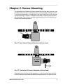
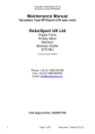
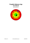
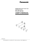
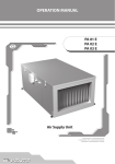
Red LED Tacho Sensor
User Manual
Smart Avionics Ltd.
Revision: 1
www.smartavionics.com
16/11/2013
Red LED Tacho Sensor: User Manual
Copyright © 2003-2013 Smart Avionics Ltd.
Table of Contents
1. Introduction ................................................................................................. 1
1.1. Tacho Sensor Description ................................................................ 1
1.2. Specifications ................................................................................... 2
2. Sensor Mounting ......................................................................................... 3
A. Connections ................................................................................................ 7
www.smartavionics.com
iii
iv
www.smartavionics.com
List of Figures
1.1. Side View .................................................................................................. 1
1.2. Sensor View ............................................................................................. 1
2.1. Rear View of Sensors Mounted on Rotor Head ...................................... 3
2.2. Front View of Sensors Mounted on Rotor Head ..................................... 3
2.3. Sensors Mounted On Rotor Head ........................................................... 5
www.smartavionics.com
v
vi
www.smartavionics.com
Chapter 1. Introduction
This manual describes the Smart Avionics Red LED Tacho Sensor (hereafter
referred to as “the tacho sensor”). The tacho sensor is primarily intended to
be used to sense the rotor RPM when balancing a gyroplane or helicopter
rotor but it can also be used on aircraft propellers and many other kinds of
rotating object.
1.1. Tacho Sensor Description
The tacho sensor consists of a light source, a light detector and a signal
processor all packaged together as one robust unit. It emits bright red light
which is reflected back from retroreflective tape that is attached to one rotor
blade and subsequently detected. Digital Signal Processing techniques are
used to increase the tacho sensor's immunity to spurious flashes of light and
general changes in the ambient light level.
Fig 1.1. Side View
Fig 1.2. Sensor View
www.smartavionics.com
1
Specifications
A single M6 mounting hole is provided and this allows the tacho sensor to
be positioned alongside the accelerometer. It is OK to enlarge the hole to 1/4"
diameter (6.35mm) if you wish. The region of the case which the hole passes
through is resin filled and, therefore, will not collapse when the fastener is
tightened sufficiently to prevent the tacho sensor from rotating. Nonetheless,
to avoid damaging the plastic case, use washers and don't tighten more than
is required.
The tacho sensor needs to “see” the retroreflective tape for a minimum of
about 200 µS per revolution to detect it. The length of tape required increases
as the RPM is increased or as the distance from the tape to the axis of
revolution increases. At 3000 RPM, the required length of tape is 1% of the
circumference so, for example, if the tape was attached 30cm (approx 12")
from the axis of revolution, the required length of tape would be a little under
2cm (3/4"). At lower RPMs or when the tape is attached nearer to the axis of
revolution, the minimum length of tape required reduces proportionately but
it is recommended that you always use a few cm of tape if possible as this
will help the tacho sensor reject spurious reflections. The tape length must
be shorter than 1/2 of the circumference. That may be a concern if you are
measuring the RPM of a very small diameter rotating object.
When the tacho sensor cannot detect the moving tape, it flashes the LED
slowly. This serves two purposes: it saves battery power and it makes it easier
for you to align the tacho sensor and the tape when the ambient light level is
high because you can perceive the flashing light easier than if the light was
on continuously.
1.2. Specifications
The sensor's specifications are:
Sensor To Tape
Distance
1cm to 100cm.
RPM Range
60 to >100000 RPM.
Supply Voltage
3.5V to 5V at 60 mA.
Output Signal
One pulse per revolution with the rising edge
synchronised to the centre of the tape.
Dimensions
63mm (plus cable and connector) × 55mm × 24mm.
Weight
85 grams.
Mounting Hole
M6.
The tacho sensor is splash proof but should not be continuously immersed.
2
www.smartavionics.com
Chapter 2. Sensor Mounting
For gyroplane rotor balancing, the accelerometer and the tacho sensor must
be mounted on the rotor head using one or more brackets. Exactly how this
is achieved is dependent on the design of the rotor head but it can be no more
complicated than a simple L shaped bracket that is attached to the side of
the rotor head. The sensors are then mounted either side of the bracket as
shown in the following figures:
Reflective
Tape
Fig 2.1. Rear View of Sensors Mounted on Rotor Head
X Axis
Y Axis
Fig 2.2. Front View of Sensors Mounted on Rotor Head
Depending on the design of the gyroplane, it is also possible to mount the
sensors aft of the mast with the reflective tape attached to one of the rotor
www.smartavionics.com
3
blades. However the sensors are mounted, you must ensure that the reflective
tape is always aligned with the beam from the tacho sensor whatever the
position of the rotor head. i.e. moving the aircraft's control stick should not
affect the alignment.
The following general points should be observed:
• The figures show both sensors mounted together, they can also be mounted
separately, if desired.
• The bracket(s) need to be sufficiently sturdy to take the weight of the
sensors and to not resonate at any frequency less than 2 times the max
rotor RPM.
• The accelerometer must be securely mounted such that one of its sensing
axes passes through (or close to) the rotor's axis of rotation and that
sensing axis is also parallel to the rotor disk (this is the horizontal axis). If
you also want to measure the vibration in the vertical direction, the other
sensing axis should be normal (90°) to the rotor disk.
• The tacho sensor must be securely mounted such that the distance between
the LED and the reflective tape is between 1cm and 100cm. A distance of
10cm to 30cm (4" to 12") works best.
• If the background itself is reflective (light coloured paint or metal (especially
if the surface is rough)), the tacho sensor should be rotated so that the
light beam strikes the reflective tape at an angle from the normal. The closer
the LED is to the reflective tape, the more the sensor will need to be rotated.
For short distances and highly reflective backgrounds, the sensor may
need to be rotated at least 45° to minimise the spurious reflections from
the background.
Tip
When the tacho sensor is connected and the PB-3 is powered
up, the red LED will flash regularly. If the tacho sensor is receiving
a large amount of reflected light, the LED will stop flashing. To
check that the sensor is correctly orientated, move the rotor so
that the tacho sensor's beam is pointing at the most reflective
portion of the background (but not the tape). If the LED is
continuously on, rotate the sensor until the LED starts flashing.
Check that the tape still passes through the LED beam.
• The cables from the accelerometer and the tacho sensor must be securely
attached to the rotor mast (e.g with cable ties) such that they cannot
interfere with any part of the cyclic control or prerotator mechanisms.
• The PB-3 must be securely mounted so that it cannot become loose in
flight. Preferably, inside the aircraft's cockpit. As the internal tachometer
4
www.smartavionics.com
will not be used, the PB-3 can be mounted almost anywhere suitable. Do
not rely on the PB-3's Velcro™ tape alone to secure it. Consider securing
the cables such that if the PB-3 did come adrift, it would not become a
flight hazard.
Important
When the sensors, cabling and PB-3 have been installed, verify that
the normal range of movement of the rotor head is still available
and that the cables cannot become tangled in the controls, engine
or propeller.
Here we see the sensors mounted on the rotor head of an ELA gyroplane
using a simple L shaped bracket. A couple of things to note about this photo
are that the reflective tape is not visible in the photo because the rotor has
been turned and that the tacho sensor has been rotated to approximately 45°
from the normal to avoid spurious reflections from the prerotator disk.
Fig 2.3. Sensors Mounted On Rotor Head
www.smartavionics.com
5
6
www.smartavionics.com
Appendix A. Connections
The tacho sensor is fitted with a 3-pin plug. Suitable cable sockets are
manufactured by TE Connectivity (part number T01-0550-S03) and Binder
(part number 99 0406 00 03). The connections are:
Pin
Signal
1
Ground
2
Open Drain output with 1K pull-up resistor to supply.
3
3.5V to 5V supply - not reverse polarity protected so be careful!
www.smartavionics.com
7
8
www.smartavionics.com