1
WASTE WATER TREATMENT PLANT WASA SUBMISSION
7
Page 20/28
INSTALLATION OF WASTE WATER TREATMENT PLANT
7.1
Introduction:
These operating instructions serve as a manual for the operation of the wastewater treatment plant. The
instructions do not deal with professional control of the WWTP operation by a person authorised to conduct
these activities.
7.2 Parts'
•
Tank:
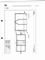
The external side of the WWTP tanks is made of wall polypropylene elements SP 80. All internal partition walls
and built-in parts are made of plastic materials, polypropylene (SP 80, KD 20 or Polypropylene). The tanks are
encased in concrete. If they are designed as self-supporting, they must be internally supported.
When installing the tank on site it is necessary to consider the local conditions and, if needed, make further
static securing. The tank is not sized to potential additional pressure loading by passing truck wheels,
foundations etc.
Mechanical — technological equipment:
The mechanical-technological equipment of the WWTP consists of a source of pressurised air— blower, finebubble aeration system, el. switchboard and a system of mammoth pumps extracting excess and return
sludge.
Wiring system
Main feeding cable leading to the WWTP switchboard:
CYKY 5C x 4 mm2
The blower is automatically controlled using a time-switch installed at the switchboard. Based on the actual
situation and characteristics of the given type wastewater and the WWTP operation it is possible to adjust the
setting so as to make it correspond to the specific type of wastewater. This means that the duration and
frequency of aerating the aeration tanks can be set and thus the volume of return sludge can be adjusted
within the internal recirculation. It is also possible to set the volume of excess sludge withdrawn to the sludge
tank.
•
Blowers
Blowers ensuring oxygen supply (type, power input):
according size of wastewater treatment plants.