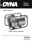
1
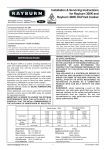
, f S - BENSON ! j INSTRUCTIONS • Installation • Commissioning • Service and Maintenance • User Manual (to be retained by the user) I \J _~_J Introduction The Benson Jetstreme 4+ series of highly efficient oil fired boilers combine the benefits of advanced design with well proven construction techniques and modern manufacturing processes. They operate at high efficiency with clean combustion and a low operating noise level. The heat exchanger is enclosed within an insulated jacket with secondary insulation attached on the inside of the case. The case is finished in white powder coat enamel and is styled to blend into any kitchen. The controls are enclosed behind an hinged panel on the front of the appliance thus reducing possible accidental damage to them. A flame viewing port facility is located at the front of the boiler directly behind the front panel. A combustion test point is located on the flue spigot of the boiler to enable the commissioning engineer to carry out his setting checks at a convenient point. The Jetstreme 4+ range is available for both Conventional and Balanced Flue systems. The Balanced Flue range is extremely versatile offering several configurations for the installation of the terminal. The Jetstreme 4+ range of both Conventional and Balanced Flue Appliances are designed to operate on Kerosene fuel oil (28 sec). The Conventional Flue appliance can also be operated on gas oil (35 sec), however it is not recommended that the Balanced Flue appliances are operated on this fuel as combustion problems could occur. All boilers are supplied with the burners adjusted for use with Kerosene (class C2) 28 sec fuel oil. Should the use of gas oil (class D) 35 sec be required to be used with a Conventional Flued appliance then the modification must be carried out at the time of installing and commissioning. Although the Jetstreme range of boilers will operate successfully on a gravity hot water system it is recommended that a fully pumped system is used for both hot water and central heating if installing a new system. The boiler is suitable for open vent and pressurised systems, however if a pressurised system is used, the manufacturers recommendations for the use of the auxiliary components must be adhered to, and pressure must not exceed 45 psi (3 bar). The Jetstreme 4+ boiler is approved by BSRIA (the Building Services Research & Information Association) for OFTEC. 1 Regulations This appliance must be installed by a competent person working to the following: The Latest OFTEC Technical Information Book 3.1992 (Installation Requirements for Oil Fired Boilers & Storage Tanks). The current Building Regulations and Local By-laws. Local Water By-laws. The current IEE regulations. BS 799. part 5: 1987 Specifications for Oil Tanks. BS 5410. part 1: 1977 Code of practice for oil firing. BS 5449. part 1: 1990 Code of practice for Central Heating for Domestic Premises. BS 6798. 1987 Specification for the installation of Gas Fired Hot Water Boilers of Rated input not exceeding 60 kW. BS 7593. 1992 Code of practice for the treatment of water in domestic hot water central heating systems. Jetstreme 4+ Installation Instructions. On completion of installation the appliance must be commissioned by a competent engineer with an understanding of the technology and with the equipment to enable him to carry out tests to set the appliance at its optimum efficiency and clean combustion. The Health and Safety at Work Act The installer should be aware of his responsibilities under the Health and Safety at Work Act whereby it is necessary for him to afford protection to persons carrying out the installation and others within the location. 2 Technical Data Model 40/52 50/70 70/90 951120 1251140 Heat Output 15.2kW 52,000 Btu 20.5kW 70,000 Btu 26.4 kW 90,000 Btu 35.2kW 120,000 Btu 41.2kW 140,000 Btu Fuel Class C2 Conventional Flue or Class D Class C2 or Class D Class C2 or Class D Class C2 or Class D Class C2 or Class D Fuel Balanced Flue Class C2 only Class C2 only Class C2 only Class C2 only Weight (Empty) Kg 85.0 Ib 187.0 85.0 187.0 118.0 260.0 159.0 350.4 159.0 350.4 Water Content It imp gal 13.3 2.9 13.3 2.9 25.0 5.5 31.0 6.8 31.0 6.8 Flow & Return connections 4 x 11/4 BSP 4 X }1/4 BSP 4 x 1 BSp1/2 4 X }1/2 BSP 4 X }1/2 BSP Flue Socket Dia. 102mm 4 in. 102mm 4 in. 127mm 5 in. 152mm 6 in. 152mm 6 in. Fuel Connection 3/8 BSP Compression 3/8 BSP Compression 3/8 BSP Compression 3/8 BSP Compression 3/8 BSP Compression Water Resistance @ 11°C Diff. 300mm 12 in. 300mm 12 in. 300mm 12 in. 300mm 12 in. 300mm 12 in. Minimum Flue Draught 8.7 N/m2 0.035 in. wg 8.7 N/m2 0.035 in. wg 8.7N/m2 0.035 in. wg 8.7N/m2 0.035 in. wg 8.7 N/m2 0.035 in. wg Maximum Flue Daught 37.4 N/m2 0.15" wg 37.4 N/m2 0.15" wg 37.4 N/m2 0.15" wg 37.4 N/m2 0.15" wg 37.4 N/m2 0.15" wg Rec. Minimum Return Temp. 50°C 120°F 50°C 120°F 50°C 120°F 50°C 120°F 50°C 120°F Maximum Working Head 27.5 metres 90 Feet 27.5 metres 90 Feet 27.5 metres 90 Feet 27.5 metres 90 Feet 27.5 metres 90 Feet Maximum Working Press. 45 psi 3 bar 45 psi 3 bar 45 psi 3 bar 45 psi 3 bar 45 psi 3 bar Electrical Supply 240 vac 50Hz 240 vac 50Hz 240 vac 50Hz 240 vac 50Hz 240 vac 50Hz Operating Temp. Range 48°C to 85°C 48°C 85°C 48°C 85°C 48°C 85°C 48°C 85°C c.F. Only Class C2 only Table 1 3 !. Int. Diameter Height Volume 40/52 292mm 300mm 0.02M3 50/70 292mm 300mm 0.02M3 70/90 375mm 387mm 0.04M3 95/120 457mm 390mm 0.06M3 125/140 457mm 390mm 0.06M3 Table 2 Combustion Chamber Size Location The Jetstreme 4+ must be located on a level non-inflammable surface that can withstand the weight of the boiler and associated equipment. The boiler location must permit adequate ease of access for maintenance and servicing. It is recommended that the following clearances should be provided: Above the boiler To either side In front 600mm (24 inches) 25mm (1 inch) 900mm (36 inches) When choosing a site for the boiler, the major consideration is the provision of a suitable flue system and whether a Conventional type flue or a Balanced Flue type should be used. Consideration must be given to the required position of the flue, access of the oil supply from the storage tank, and the location of the air vents that may be required. If the boiler is to be located within a compartment or cupboard then the compartment or cupboard must be constructed or modified for the purpose intended. Details of these requirements are given in BS 6798: 1987 Specification for the installation of Gas Fired Hot Water Boilers of Rated Input not exceeding 60 kW. Conventional Flue If the flue is on the outside of the building then the flue must be of the insulated twin wall type to eliminate the possible formation of condensate. The flue should rise as near vertically as possible to its maximum possible length before any bends are included. The number of bends should be kept to an absolute maximum of two. No bend should have an angle less than 135°. No part of the flue internal diameter should be less than that of the flue outlet spigot diameter on the boiler. A brick chimney should be lined with a suitable stainless steel flue pipe, or other suitable non combustible lining, with the void between the lining and the masonry filled with a suitable insulating material e.g. vermiculite. The chimney must always be swept before the fitting of a liner. A draught stabiliser must not be used unless the flue pull is found to be excessive. The flue outlet should terminate at least 600mm (24 inches) above the apex of the roof, if this is not practical, or it is found that the appliance is being subjected to a down draught, then an approved cowl should be fitted to eliminate this condition. The fitting of a suitable cowl is always recommended. 4 Balanced Flue Jetstreme 4+ boilers are designed to also use a Balanced Flue system, whereby the appliance is completely sealed from the room where it is installed. Air is taken directly from the outside of the building to the burner for combustion, and then discharged again to the outside of the building. It is sometimes found that the burner noise level is increased when passing through a normal inlet/exhaust pipe, but the Jetstreme 4+ inlet/exhaust also incorporates a silencer to reduce this effect. The flue kit may be positioned so as to pass through the wall to the rear, or through a side wall to the left or right, taking due account of the building regulations and the recommendations shown in fig 5. The standard flue kit is suitable for walls up to 11 inches thick. For walls up to 22 inches thick a supplementary kit is available and can be ordered directly from Benson Heating, quoting Flue Kit No.1. Flue Kit No.2. This kit enables the balanced flue to be discharged through the wall at a high level (2 metres) above the floor. Flue Kit No.3. This kit, although still a balanced flue system, is suitable for situations where the only route for the discharge is through a flat or shallow pitched roof. The terminal guard basket supplied with the balanced flue kit must always be fitted even at high level. If the balanced flue terminal discharges within 900mm (3 feet) below a plastic gutter or overhang, the gutter must be protected with a non-combustible material. Burner Various burners are available for use on the Jetstreme 4+ boiler and all are rigorously tested for their suitability. Because burners may be added to the range from time to time, details of the burners are given within a separate document. It should be noted that the EOGB burner is referred to here; this is because the initial external BSRIA approvals for the Jetstreme 4+ were carried out with the EOBG 'Burner fitted. Oil Supply Any fuel oil leak, however small must be rectified immediately. Careful consideration must be given to the siting of the oil storage tank, taking account of: Access for delivery of oil. Proximity and relationship of tank to boiler. Visual acceptability by the customer and neighbours. Conformity to local bylaws. Building Regulations. Protection for the retention of oil in the event of a leak. Plastic oil storage tanks should comply with OFS TlOO and should be OFTEC Approved under the OFCERT Scheme. 5 Gravity One Pipe System It is recommended that the oil tank is situated so that the oil outlet from the tank is not less than lOOmrn (4 inches) above the oil burner pump. This will permit the use of a gravity feed system from the tank to the burner. The oil tank outlet must not exceed 4 metres (13 feet approx.) above the burner pump. All Jetstreme 4+ appliances are supplied ready to be used on a gravity system. If it is not possible to use a gravity feed system then conversion to a two pipe system must be carried out, this is explained on page 7. A filter of the metal bowl type with a micronic filter element must be fitted in the oil supply line. A valve must not be fitted on the oil return pipe, if this pipe should become blocked it may cause the pump to faiL The installer MUST supply and fit a fire check valve in the oil supply line, and this valve must comply with BS 799: part 5: 1977 Specification for Oil Storage Tanks. The following table shows the relationship between the head of oil, the diameter of the supply pipe and the flow. GRAVITY ONE PIPE OIL SYSTEM - TANK OUTLET ABOVE BURNER FILL VENT JETSTREME 4 + FIRE CHECK VALVE SENSOR 4 METRES MAXIMUM FILTER \ SLUDGE COCK FIRE CHECK VALVE t 20 mm PER METRE FALL .... Fig. 1 FLOW - L MAX PIPE LENGTH TABLE GIVING MAXIMUM PIPE LENGTH 'L' I I MAXIMUM L METRES r, "ETRES 05 LO PIPE lOmrnOD 10 20 40 60 PIPE 12mmOD 20 40 80 100 1.5 2.0 Table 3 6 Two Pipe System Where it is not possible to install a gravity oil supply system then a two pipe pumped system must be installed. The oil in this arrangement is drawn from the tank by the pump on the burner, and any excess is returned via the second pipe to the tank If a two pipe system is to be fitted, the pump on the burner will require to be modified from that supplied (See Burner Manual). The diagrammatic layout of the pipe work for a two pipe system is shown below. Where the tank is below the level of the oil pump the two pipes should each be the same length into the oil. If the return pipe is shorter than the flow, then it will be necessary to fit a spring loaded non-return valve to this pipe. On a two pipe system the pump vacuum should not exceed 0.4 bar (30cm Hg). If this is not observed then dissolved gas will be released from the oil resulting in oil starvation to the burner and repeated boiler 'lockouts'. A filter of the metal bowl type with a micronic filter should be installed in the oil return pipe. If this pipe should become blocked it may cause the pump to fail. The installer MUST supply and fit a fire check valve in the oil supply line, and this valve must comply with BS 799: part 5: 1977 Specification for Oil Storage Tanks. The pipe size requirement is given in the table below. TWO PIPE OIL SYSTEM - TANK OUTLET BELOW BURNER JETSTREME 4 + FIRE CHECK VALVE SENSOR RETURN PIPE .-------------;;::::~~F=F::r::F1 '.::t:J[j.Lf-jf----- RETURN PORT VENT FILL NON RETURN VALVE A Fig. 2 FILTER SLUDGE COC~K~~~~~~~~~~~~L-~ FLOW 20 mm PER METRE FALL ----Il1o - - RE1\.lRN TABLE GIVING MAXIMUM SUCTION PIPE LENGTH 'L' HMETRES MAXIMUM L METRES 0 0.5 1.0 1.5 2.0 3.0 3.5 PIPEI0mmOD 35 30 25 20 15 8 6 PIPE 12mmOD 100 100 100 90 70 30 20 Table 4 7 TWO PIPE OIL SYSTEM - TANK OUTLET ABOVE BURNER RETURN PIPE VENT FILL SLUDGE COC~KxH~~~~~~~~~~~ ____________r JETSTREME 4 + FLOW - 20 mm PER METRE FALL H - - RETURN FIRE CHECK VALVE SENSOR LJ 1-t;4.~*=;;;;;;;;;;~~ 'lJ~I--- LMAX RETURN PORT NON RETURN VALVE Fig. 3 FIRE CHECK VALVE FILTER TABLE GIVING MAXIMUM SUCTION PIPE LENGTH 'L' HMETRES MAXIMUM L METRES 0 1.0 0.5 15 2.0 3.0 35 PIPE10mmOD 35 30 25 20 15 8 6 PIPE 12mmOD 100 100 100 90 70 30 20 Table 5 Note: In all cases the tank should be positioned so that it slopes away from the outlet by 20mm per metre of length of tank (1/4 inch per foot length). This is to ensure that any impurities do not contaminate the oil supply feed. The customer should be shown how to remove these impurities from time to time, or this should be carried out at its service or maintenance check. Connections on the oil supply pipe should be made using compression fittings where possible. Galvanised pipe or fittings MUST NOT be used. Always check sealing compounds for their suitability for use in conjunction with oil. 8 Air Supply Conventional Flue For a conventional flue boiler, air is required, not only for combustion, but also for ventilation, and where the boiler is located in a compartment or cupboard additional ventilation is required. The volume of air required is 550mm2 jkW of boiler output. The requirements for the Jetstreme 4+ range of boilers are given below. information supplied by: OPEN FLUE BOILER IN ROOM OPEN FLUE BOILER COMPARTMENT VENTILATED FROM OUTSIDE A OPEN FLUE BOILER COMPARTMENT VENTILATED FROM ROOM Fig. 4 Model 40/52 ~ 70/90 95/120 125/140 Boiler in a room ventilationIn 83.6cm2 Out Nil 112.8cm2 Nil I 45.2cm2 Nil I 93.6cm2 Nil 226.6cm2 Nil Boiler in a compartment ventilation In 16.72cm2 Out 83.6cm2 225.6cm2 112.8cm2 290Acm2 I 45.2cm2 387.2cm2 I 93.6cm2 453.2cm2 226.6cm2 Boiler in a compartment in a room vent to In 83.6cm2 room Out Nil vent to In 250.8cm2 compo Out I67.2cm2 112.8cm2 Nil 338Acm2 225.6cm2 I 45.2cm2 Nil 435.6cm2 290Acm2 I 93.6cm2 Nil 580.8cm2 387.2cm2 226.6cm2 Nil 679.8cm2 453.2cm2 Table 6 Extraction Fan- Conventional Flued Boiler only. If an extraction fan is fitted either into the room or an adjacent room, to where the boiler is fitted, it MUST NOT have any effect on the flue pull of the boiler. If the extractor fan DOES have a detrimental effect on the boiler, then extra ventilation must be introduced into the boiler room or to the room adjacent to where the boiler is installed. 9 INSTALLATION INSTRUCTIONS Electrical Supply Warnings:- This appliance must be earthed. All wiring and electrical work must be carried out by a competent electrician working to the current lEE Regulations. The electric supply must be made via a fused double pole isolation switch with at least 3mm between the contacts. The fuse rating is 6 amp. All conductors must have a cross sectional area of O.75mm2 or greater. Electrical circuit diagrams are provided later in this manual (see pages 15-17). Conventional Flue Carefully remove the packing from around the boiler. Fit the water flow and return fittings into the required positions on the boiler. If only one flow and one return connection is required then they should preferably be positioned on opposite sides of the boiler. Place the boiler in the required installation position and remove the top panel, by lifting it upward, and the lower front panel, by pulling it forward. Place the top and front panels safely to one side so that they will not be damaged. Locate the first section of the flue into the flue spigot and seal the area between the flue and the boiler spigot with ceramic rope and fire cement. Brackets should be fitted to help support the flue as it is being built. It is recommended that the boiler be covered to prevent masonry falling into the boiler when making a hole in the wall or ceiling. If the flue is to pass through an existing brick chimney, a stainless steel flue liner should be used and the cavity between the liner and the brickwork should be insulated with vermiculite or similar. The first section(s) from the boiler to within the brick chimney should be of twin wall flue pipe. On completion of the flue installation make good any area where the flue passes through the wall or ceiling. Replace the cover and refit the screw and serrated washer. Complete the pipework to the boiler. Connect the oil supply line and terminate within 450mm (18 inches) of the oil pump on the burner. From this point fit the flexible hose supplied to the burner connection (in the case of a two pipe system the installer will have to supply the second hose). The installer should fit a fire check valve with a fusible link located above the burner. Insert the electrical four pin plug on the end of the fly lead from the burner into the socket located on the underside of the control panel. Refit the top and front panels, by placing the panels in position and then pressing to lock them into the clips. 10 Balanced flue Before starting the installation, check that the proposed position of the balanced flue terminal on the outer wall conforms with the requirements of fig 5. Fig. 5 A Below a gutter or sanitary pipework G From a surface facing the terminal B Horizontal from opening, airbrick, window etc. H Vertical from terminals on the same wall C Above ground or balcony level I D Below eaves or balcony J Below an opening, airbrick, window etc. E From an internal or external corner K From vertical sanitary pipework Horizontal from terminals on the same wall F From a terminal facing a terminal A B C D E F 'G H I J K - 600 - - 600 - - - - 600 - 600 1000 - 600 600 600 1000 600 600 600 600 600 600 600 1500 600 600 600 600 600 1000 - 600 - - 600 - - - - 600 - 600 600 600 600 600 - - - - 600 700 Building Regulations England and Wales 1990 Scotland 1990 Balanced* Low Level* Northern Ireland 1990 British Standard BS 5410 Part 1 1977 Table 7 *Where the terminal is within 1 metre of any plastic material, such material should be protected from the effects of combustion products of the fuel. There are additional general requirements in most Regulations and Standards that the flue must be ~ positioned so that it does not cause a nuisance and permits the dispersal of combustion products. ® CCl!F1T"Ili<C 11 Balanced Flue Carefully remove the packing from around the boiler. Fit the water flow and return fittings into the required positions on the boiler. If only one flow and one return connection is required, then they should preferably be positioned on opposite sides of the boiler. Place the boiler in the required installation position and remove the top panel, by lifting it upward, and the lower front panel by pulling it forward. Place the top and front panels safely to one side so that they will not be damaged. Mark the position of the flue duct and then remove the boiler. Check the position for the duct (see fig 6), and cut a hole through the walL Check on completion that the duct passes through the hole in the wall, ensuring that there is at least a 70mm projection. Fig. 6 Replace the boiler into position and remove the 4 screws located in the balanced flue outlet on the boiler. Remove the access plate from the end of the balanced flue duct, and locate the duct over the four fixing holes on the outlet of the boiler. Ensure that the gasket is correctly fitted between the two faces. The spigot should then be placed in position, face down again with a gasket in place. The four fasteners should be tightened, and the exhaust tube slid into the duct and inserted into the spigot. Joints should then be sealed with fire cement prior to fitting the access cover. The wind cowl should then be fitted over the end of the duct, ensuring the gap between the dish and the extension tube on the exhaust is not more than 40 mm. Locate the terminal guard basket over the wind cowl and mark the four fixing points. Drill and plug, and fix into position. Unscrew the cover to the electrical control panel and then connect the mains input (and any additional wiring) passing the wires through the cable clamp (see figs 7-13). On completion replace the cover and refit the screw and serrated washer. FIT THE BALANCED FLUE AIR SUPPLY PIPE TO THE SPIGOT ON THE BALANCED FLUE TERMINAL DUCT AND ro THE INLET OF THE BURNER. SECURE WITH THE JUBILEE CLIPS PROVIDED. Complete the pipework to the boiler. Connect the oil supply line and terminate within 450mm (18 inches) of the oil pump on the 12 burner. From this point fit the flexible hose supplied to the burner connection (in the case of a two pipe system the installer will have to supply the second hose). The installer should fit a fire check valve with a fusible link located above the burner. Insert the electrical four pin plug on the end of the fly lead from the burner into the socket on the underside of the control panel. Refit the top and front panels, by placing them in position and then pressing to lock them into the clips. Programmer This is an optional extra which can be fitted either when the boiler is purchased, or at a later stage. See page 26 for further information. COMMISSIONING Combustion - The responsibilities of the commissioning engineer are clearly stated in British Standard 5410 part 1: 1971 and these responsibilities must be adhered to. It is important that the boiler is commissioned by a competent engineer with an understanding of the technology and with the equipment suitable to enable him to carry out the tests to set the appliance at its optimum efficiency and with clean combustion. It is strongly recommended that an OFTEC (Oil Firing Technical Association for the Petroleum Industry) registered engineer is used for this purpose. If difficulty is found locating an engineer then contact can be made through OFTEC on telephone number 01737-373311. Electrical - Checks for electrical safety should be carried out by a competent electrician with a working knowledge of the current IEE Regulations. Fuel - Bleed all the air from the oil supply line to ensure an uninterrupted supply of oil to the burner. This can be achieved on gravity systems by loosening the suction line connection. It is essential that any oil spillage is contained and the area be cleane~ on completion. On a two pipe system purging can be carried out by running the oil burner and resetting after lockout. Water - Ensure that the system is full of water and that all air is bled from the radiators and boiler. After firing and checking that the system is free of water leaks and is working satisfactorily it is recommended that a suitable anti-corrosion additive is introduced into the system (e.g. Fernox). This is done by partly draining down the system, putting in the additive and then topping up with fresh water. 13 First Firing 1. Ensure that the Boiler thermostat and the limit thermostat phials are located in their respective phial pockets and are fully home. 2. Turn ON any isolating taps in the oil supply line. 3. Switch ON the mains electricity isolating switch. 4. Set the programmer I time clock, if fitted, to an 'ON' position for both CH and HW. 5. Set the room thermostat to its maximum position. 6. Set the cylinder thermostat to its maximum position. 7. Turn boiler thermostat to its maximum position. - At this point the burner will start to run and a series of clicks will be heard as the ignitor attempts to fire the oil. If the oil fires satisfactorily the burner noise will be heard. If the oil fails to ignite, the burner will go to lockout mode. A red light will show on the control panel to indicate lockout. Turn the boiler thermostat on the control panel to the OFF position and wait 30 seconds. Press the manual reset button on the burner, if the lockout is reset then this button will remain in, and the lockout light will extinguish. Again turn the thermostat to its maximum position to repeat the ignition sequence. This sometimes has to be repeated several times before getting ignition, particularly with two pipe systems. Once the flame has been established allow the burner to continue to run for approximately 10 minutes before turning off the boiler thermostat, and inspecting for water or oil leaks. It may also be necessary to again bleed the system. Once satisfied that the system is again sealed, remove the combustion test point screw from the flue spigot and insert the sample probe of the test equipment. Turn on the boiler thermostat, and carry out the combustion tests, referring to the information given in the appropriate tables (see tables 8-10). All burners used on the Jetstreme 4+ are factory set at a pressure of approximately 20 p.s.i. below that required for maximum rated output. The oil pressure and the combustion level must be verified by on site testing, and adjustments made where necessary. Information regarding the methods of burner adjustments are explained in the burner technical booklet supplied with these instructions. IMPORTANT To ensure that the appliance is covered by the 2 year guarantee the installation details section of these instructions and the warranty card should be completed. The warranty card must be returned to Benson Heating within the registration period of 28 days. This does not affect the statutory rights of the purchaser. 14 STANDARD WIRING DIAGRAMS Internal Wiring Diagram: ~;s;- :-- --- --- --- --- --- --- --, EARTH BIlILER THERMOSTAT LIMn THERMOSTAT CONTROL PANEL i I I I I I I I I BURNER ON BLACK LOCKOUT I I I I ----~ 0----- ~J;~;-- I ;'ov At SlA'I. Y I I 1~ll.rf/~fH I PlMR 'ON' INDICATIIR Fig. 7 -, ,I I I 'I'-l-=i- I L<t...9--U 1 i i ~ I BURNER _ _ _ _ _L_~~ External Wiring Diagram: ROOM T/STAT 0000 000 Ll N2 [3 4 5 6 7 a 9 10 JETSTREHE CONTROL PANEL PUMP ON/orF FROM ROOM THERMOSTAT Fig. 8 15 PROGRAMMER WIRING DIAGRAMS Internal Wiring Diagram: , ---------------------l PROG RAM I£R CHASSIS~' BmLER EARTH THERMOSTAT CONTROL PANEL LIMIT H£RKlSTAT zzz ~~~ ..... ""X '" "' ~---+-H~----4--. LOCKOUT r-: ---fXlIBMN ylRHa Fig. 10 fUS£ SA 241111 K; SU'PI. Y I I I~&r~tt ' L PIIVtR 'ON' INDICIITlR I !"'j...:l I !.2..£...JJ l l ~ I i BURNER ____ L :~ External Wiring Diagrams: RO!lH THERH!lSTAT 000 LI N2 E3 4 :) 6 7 8 0 9 ]0 JETSTREME CONTROL PANEL Fig. 11 GRAVIlY HOT WATER AND PUMPED CENTRAL HEATING 16 External Wiring Continued: FULLY PUMPED SYSTEM WITH ZONE VALYES ZIK WLVE C.H. ZIJNE VALVE Ill.', H.I.', CYlINDER Cll. ROOM THERMOSTAT THERMOSTAT '---I ~t--llJ' £~r--lli' pii;;71 it«:,I"""'lE i[ .~ ~.~,'l"-++-I-+' L::. --\,4 - -- ~. L' 3 I 10 1 5 2 I 6 C 6 . 3 6 6834523 10 1 8 2 JUNCTION BOX 1 2 3 10 ... 6 3] ~ 5 r .--- ..- --, !~ - : ••••J [ ! :: ;....... I : IPTlrtlAL : ; -------H---- ~ - ___~=:.__==___ !!~J"."'!; 000 UN2E345678910 JETSTREME CONTROL PANEL Fig. 12 FULLY PUMPED SYSTEM WITH MID POSmON DIVERTER VALYES MID POSITION KII. CYLINOCR r------l r;i.---~ DlVERTER VALVE C.H. ROIJ4 THERMOSTAT THERMOSTAT '---I ~~ ~ ~~ L___ ~. A;j-'I-- -J I 6 310852 ]0 6 5 3 4 8 2 3 JUNCTION BOX 1 2 3 10 4 6 5 9 3 ~ I 8 PUMP ~ EXTERNAl IIIRING u o ~O 0 ( 4 5 6 7 8 9 W Fig. 13 JETSTREME CONTROL PAI£L 17 TECHNICAL SPECIFICATION - KEROSENE (CONVENTIONAL FLUE) MODEL 40/52 50/70 70/90 951120 1251140. KW Btu/hr 14.3 48,800 20.37 69,500 26.4 90,000 36.0 122,700 39.7 135,300 BURNER E.O.G.B. Sterling 40 (Eng 108) 40 (Eng 108) 50 (Eng 120) 50 (Eng 120) 50 (Eng 120) HEAD SETTING Distance from front of Blast Tube to Nozzle 43mm 43mm 43mm 43mm 43mm PL 10-5-16-8 10-5-16-8 6-7-19-10 10-8-6-19-10 10-8-1 0-6-19-10 NOZZLE Danfoss 0.4580'S 0.6080'H 0.8580'H 1.0 60'S 1.10 60'S OIL PRESSURE Bar P.S.!. 7.6 110 7.6 110 7.6 110 9.3 135 9.3 135 OUTPUT BLAST TUBE _ I ..... ..... (lQ ....., , \ ._. ; AIR SETTING 2.5 16 11 14 16.5 SMOKE No. 0 0 0 0 0 NET FLUE GAS TEMP °C 149 197 234 189 196 CO2 % 12.5 12.4 12.5 12.5 12.5 Llhr Kg/hr g/hr 1.73 1.35 0.38 2.45 1.92 0.54 3.41 2.65 0.75 4.31 3.36 0.95 4.68 3.65 1.03 c.... FUEL CONS ------- WATERFLOW glhr RATE 300 350 345 500 ------- 520 Table 8 TECHNICAL SPECIFICATION - KEROSENE (BALANCED FLUE) MODEL 40/52 50/70 70/90 95/120 125/140 OUTPUT KW Btuthr 14.7 50,200 19.93 68,000 26.0 88,700 34.6 118,100 41.0 130,000 BURNER E.O.G.B. Sterling 40 (Eng 108) 40 (Eng 108) 50 (Eng 120) 50 (Eng 120) 50 (Eng 120) HEAD SETTING Distance from front of Blast Tube to Nozzle 43mm 43mm 43mm 43mm 43mm BLAST TUBE PL 10-5-16-8 10-5-16-8 6-7-19-10 10-8-6-19-10 10-8-10-6-19-10 NOZZLE Danfoss 0.4580"5 0.6080oH 0.85800 H 1.060°5 1.1060"5 OIL PRESSURE Bar P.S.I. 7.6 110 7.6 110 7.6 110 9.3 135 9.3 135 AIR SETTING 5 18 15 17 26 SMOKE No. 0 0 0 0 0 ...... 1.0 NET FLUE GAS TEMP °C 167 222 212 201 217 CO2 % 12.6 12.6 12.4 12.5 12.6 FUEL CONS Lthr Kglhr glhr 1.73 1.35 0.38 2.45 1.93 0.54 3.54 2.76 0.78 4.31 3.36 0.95 4.77 3.71 1.05 300 320 340 500 520 WATERFLOW RATE g/hr . Table 9 TECHNICAL SPECIFICATION - GAS OIL (CONVENTIONAL FLUE ONLY) MODEL t:5 40/52 50/70 70/90 95/120 125/140 OUTPUT KW Btuihr 15.1 51,600 19.05 65,000 25.5 87,000 34.9 119,000 39.3 134,000 BURNER E.O.G.B. Sterling 40 (Eng 108) 40 (Eng 108) 50 (Eng 120) 50 (Eng 120) 50 (Eng 120) HEAD SETTING Distance from front of Blast Tube to Nozzle 43mm 43mm 43mm 43mm 43mm BLAST TUBE PL 10-5-16-8 10-5-16-8 6-7-19-10 10-8-6-19-10 10-8-10-6-19-10 NOZZLE Danfoss 0.4080 H 0.5080 H 0.6060°5 0.7560°5 0.8560°5 OIL PRESSURE Bar P.S.I. 10.4 150 10.4 150 11.0 160 11.7 170 11.7 170 AIR SETTING 3.5 10.5 11.5 13.5 19.5 SMOKE No. 0 1 0 0/1 1 0 0 NET FLUE GAS TEMP °C 219 243 208 192 208 CO2 % 12.5 12.5 12.5 12.4 12.5 FUEL CONS Llhr Kg/hr g/hr 1.73 1.45 0.38 2.18 1.83 0.48 3.00 2.50 0.66 3.90 3.23 0.86 4.50 3.75 0.99 270 320 420 500 540 WATERFLOW RATE g/hr Table 10 SERVICING AND MAINTENANCE INSTRUCTIONS Notes on Servicing The boiler should be serviced annually by a competent engineer. Failure to observe the correct procedures could result in a danger to the user. The cleaning should be such that all residue is removed from both the interior and exterior of the boiler. On completion of the interior cleaning the baffles MUST be fitted as per fig 14. If they are assembled in an incorrect manner damage may occur and the warranty may be invalidated. UPPER BAFFLE .A'-T--l'--" ALL FLANGES TO THE TOP MID BAFFLE - - - / LOWER BAFFLE BAFFLE CUTAWAY FRONT OF BOILER BAFFLE CONFIGURATION Fig. 14 All damaged components should be replaced or made good. The burner should be checked and cleaned. The room sealing of the Balanced Flue appliance MUST be maintained. The Burner settings should be checked against those in the Technical Specifications in this manual (see figs. 8-10) and be adjusted, if necessary, so that it is operating at its optimum efficiency and with clean combustion. It is recommended that the flexible oil pipes to the burner are replaced every two years. 21 FAULT FINDING Burner Fails to Start If the burner has failed to operate check the following: 1. Ensure that the mains supply switch is ON. 2. The thermostats are turned to the required setting. For test purposes only, turn the thermostats to their maximum setting. But remember to reset them later. 3. Is the Timer/Programmer set to an On period? 4. Check that the Reset Button on the burner control box is not illuminated. 5. Check that the Limit Thermostat on the underside of the facia is fully in. 6. Again start the ignition procedure. Burner goes to Lockout 1. Remove the lower front panel. 2. On the burner control box a glowing red button will be noticed. This is the Lockout Reset Button. 3. Turn the boiler thermostat to the OFF position. 4. Press the Lockout Reset Button fully home. 5. Release the Lockout Reset Button. The light will go out and should remain so. 6. Turn the boiler thermostat to the required setting. The ignition cycle should then automatically commence. If the appliance is still failing, check the following: - Ensure that there is an adequate supply of oil in the Tank. a. Oil supply That the supply valves have not been turned off. That the fire check valve has not operated. Was the storage tank allowed to run dry before being refilled thereby creating air in the supply pipe. Check fuel grade to match burner is correct. Check for correct oil pressure (See Technical Specification). If a one pipe system, Bleed supply pipe at the boiler. b. Air lock If a two pipe system continue to rectify lockout until air lock is cleared. c. Blocked Nozzle Clean or replace with new nozzle as per the manufacturer's instructions. (See Burner Manual). Check spark gap. (See Burner Manual). d. No Spark Check Burner Control Box Spark output. (See Burner Manual). Replace as necessary. 22 USER INSTRUCTIONS Warning Before carrying out any work on the appliance it MUST be isolated from the mains electrical supply. DO NOT adjust in any way the setting of the oil burner or its controls. This type of work must only be carried out by a competent engineer. Should an oil spillage or leak occur it MUST be rectified immediately. Oil must not be allowed to soak into the ground where it can pollute ground water and water courses. Contact your oil supply company or engineer. Located on the front of the boiler and directly behind the front panel is a flame viewing point. To view the flame the blanking cap must be removed but in doing so exercise caution as it may be very hot if the boiler has been operating. Only view the flame from a safe distance. This appliance as with all similar appliances should be serviced at least annually to maintain the efficiency and clean combustion of the boiler. Failure to do so could severely reduce the life of the boiler. It is recommended that servicing should take place prior to the summer shut down to minimise corrosion during the summer months. Lighting Instructions Ensure that: 1. All oil taps and valves are open. 2. An adequate supply is in the oil storage tank. 3. Mains isolation switch is ON. 4. Room thermostat is set at the required setting. 5. Cylinder thermostat is set at the required setting. 6. Timer I Programmer is set at an ON period for Central Heating and Hot Water. 7. Turn the boiler thermostat to its maximum setting. The boiler should now commence its ignition cycle. a. Fan motor runs. b. After approximately 5 seconds the oil solenoid valve opens and oil is sprayed from the burner nozzle into the combustion chamber. c. Immediately oil is sprayed from the nozzle, ignition takes place. If ignition is satisfactory allow the boiler to continue with its operating sequence being controlled by the thermostats and the time controller. The GREEN NEON will illuminate to indicate that the boiler is operating and that the burner is being fired. During the burner OFF periods within the operating cycle the GREEN NEON will be extinguished. If igniti()n fails the burner will go to lockout. This is indicated by the illumination of the RED NEON on the control panel. Follow the instructions for 'Lockout Reset', shown on page 25. Under normal running conditions the boiler will automatically operate daily to the programme set and without further adjustments. For adjustment of the programmer, if fitted, (see pages 24, 26 and 27). 23 The Control Panel and its Components CONTROL PANEL (COVER OMITTED FOR CLARITY) GREEN NEON OF~ 10FF g~~~~~~~ I I I I RED NEON ON,-,_ _--''ON i iSET'. AnI/ 1iI,..... .aD. SElECT PROGRAMMER YES LIMIT THERMOSTAT / BOILER THERMOSTAT Fig. 15 Programmer - This is an optional extra - The programmer is of a compact advanced design that can be programmed to vary the ON/OFF periods for the Hot Water and Central Heating independently of each other on fully pumped systems, but on gravity hot water with pumped central heating, the central heating times work in conjunction with the hot water times. The operating times for Saturday and Sunday can be set to different times to those of the weekdays. To set the programmer refer to the programmer section of these instructions (pages 26-29). Boiler Thermostat - This controls the temperature of the water leaving the boiler to be circu.lated around the system. The boiler must not be run for- long periods with the boiler thermostat set at the low end of the range. This creates condensation within the combustion chamber which over time will damage the interior surface. For the most efficient use of the system the boiler thermostat should be set at the higher end of the range. Radiators are designed for flows of approximately 80°C with an 11°C differential to the return. Limit Thermostat - This is a safety device that switches off the boiler in the case of a failure in the boiler thermostat. This can be reset by pressing in the button located on the underside of the control panel upwards where it should be retained. Should this limit thermostat repeatedly operate then you should consult your engineer. Green Neon - This only illuminates when the Burner is in its operating mode. Red Neon - This is only illuminated when a burner fault develops and the lockout procedure occurs. (Also the lockout button on the burner control box will illuminate) both lights will remain on until the burner is reset or mains electricity to the appliance is disconnected. 24 Lockout The Lockout condition is a built in safety device which comes into operation when the burner controls suspect or register that a fault has developed that could cause damage to the burner. Several things can create this situation such as: Oil tank allowed to run out of fuel. The valves in the oil line have been turned off. The fire check valve has operated. Air in the supply pipe; usually caused by allowing the tank to run dry, then on refilling not bleeding the air from the supply pipe. Wrong grade of fuel supplied. Water contamination of the oil tank, this is quite common where the inspection doors or vent caps etc. have been left open. Faulty or contaminated filter causing blockage to the burner nozzle. No ignition at the burner nozzle due to burner fault. In most cases it is recommended that a qualified service engineer is employed to correct the fault. Lockout Reset If the boiler goes to lockout condition, this is indicated by the illumination of the RED NEON on the control panel. To reset the burner the following procedure should be followed: 1. Remove the lower front panel. 2. On the burner control box a glowing red button will be noticed. This is the Lockout Reset Button. 3. Turn the boiler thermostat to the OFF position. 4. Press the Lockout Reset Button fully horne. 5. Release the Lockout Reset Button. The light will go out and should remain so. 6. Turn the boiler thermostat to the required setting. The ignition .cycle should then automatically commence. 7. If Lockout continues to re-occur then a competent engineer should be consulted. Do not attempt to adjust the burner or its controls. Note: If the oil storage tank has been allowed to become empty then air may be present in the supply pipe. The oil supply pipe will require either 'bleeding' if it is a one pipe system or the continued resetting of the lockout to clear the air on a two pipe system. It is always useful to consult your installer as to which system is fitted. 25 Failure of Burner to Operate If the burner has failed to operate, check the following: 1. Ensure that the mains supply switch is ON. 2. The thermostats are turned to the required setting. For test purposes only turn the thermostats to their maximum setting. But remember to reset them later. 3. Is the Timer/Programmer set to an On period? 4. Check the Reset Button on the Burner control box is not illuminated. 5. Check that the Limit Thermostat on the underside of the facia is fully in. 6. Again start the ignition sequence. If the appliance continues to fail to ignite consult your service engineer. Cleaning the Case The case may be cleaned by using a mild soap solution or a propriety cream cleanser on a damp soft cloth. DO NOT USE an abrasive cleaner or scouring pads. Servicing Servicing should be carried out by a competent Engineer who is OFTEC registered or is registered under one of the oil companies maintenance schemes. Programmer OFF I TIMED •TIMED OFF ONCE ONCE ON ' - - - - - - - - - - - ' ON •• -H.W. ADV SET? • C.W. ADV Fig. 16 The programmer is located behind the hinged cover on the facia panel, adjacent to the boiler thermostat contol knob. On fully pumped systems the programmer will allow the hot water and central heating to work independently of each other, if required. However, on systems with gravity hot water and pumped central heating, the hot water shares the central heating programme. The programmer can be set to allow for different times on week days and weekends, pre-set programmes are protected in the event of a power failure by a rechargeable battery back-up. On a fuHy pumped system it is possible to have four 'On' settings (2 for centra] heating and 2 for hot water) and four 'Off' settings per day. Programmes can be advanced using the 'On' facility to override what would otherwise be an 'Off' period. 26 During installation, and before commissioning, the presence of the blue tag connector on the back of the programmer must be checked and matched to the requirements of the system, i.e. left in place for a pumped central heating with gravity hot water, or, in the case of a fully pumped system, removed (See fig. 17). VIEW OF REAR OF PROGRAMMER TO SHOW TAG _ ........ MPS2211)4 . - by APPI.IANCE COMPONENTS ~ED VOLTAGE 220 250 v- 50 Hz MAlOMUIIII.OAD 2 (1) A TOTAL 0 ~pl I REART55 _T54 :E i :E '"rn .,~ i., 0 '"£: .,i! i i ~ r ~-~ ~ IJ 0 ~ "51 ..z Z llI: .. zm "'z "'z /I) !;j "'"' ~ ~!l Iirn r rni!! ~ lll., :E I~ ! ~ !ii1l "0 ........ IJ_ c~ Fig. 17 Set the Clock a. Switch on the mains supply to the boiler. b. Press & release the button marked SET. The question SET CLOCK? will appear in the display. Press & release the button marked YES. c. The day section of the display will flash. Using the + or - buttons set the correct day. Press & release SET. d. The hour section will flash. Using the + or - buttons set the correct hour. Note the am or pm. Press & release SET. e. The minute section will flash. Using the + or - set the correct minute. Press & release SET. f. The question SET PROG? will be displayed. Either Press & release SET to display the time of day that has been set. or Press & release YES if a change to the standard programme is required. 27 ~ ~~- Standard Programmer Times. The programmer is supplied ready set to a standard programme of times as listed in the table below. IT different times to the standard settings are required then these can be changed. This is done by following the question and answer instructions in the paragraph 'Setting the Programme times'. Programme Monday-Friday iCH HW Saturday & Sunday HW CH 6.30 am 7.00 am 7.00 am ONt Start of first ON period 6.30 am OFFt End of first ON period 8.30 am 8.30 am 9.00 am 9.00 am ON2 Start of Second ON period 4.30 pm 4.30 pm 4.00 pm 4.00 pm 10.30 pm 10.30 pm 11.00 pm OFF 2 End of Second ON period Table 11 • i 11.00 pm Setting the Programme Times a. Press & release the button marked SET. The question SET CLOCK? will appear in the display. As this has already been done press & release the button marked SET. b. The question SET PROG? will appear in the display. Press & release YES button. c. The display will now show the question SET CH MON-FR1? Press & release YES if a change to the Central Heating times are required. Or Press & release SET if no change is required. cm If YES was pressed the display will show the first Central Heating ONI time. By pressing the + or - buttons the time will be altered in 10 minute stages. When the correct time is shown in the display Press & release SET. The OFFl time will now show in the display repeat as ONI setting. Repeat for ON2 and OFF2. d. After setting CH OFF2 the display will show SET HW MON-FRI? Press & release YES if a change is required to the Hot Water times. Or Press & release SET if no change is required. IT YES was pressed follow the same procesure as c(i). e. After pressing HW OFF2 the display will show SET CH SATSUN? Follow the same procedure as c & c(i). f. After setting CH SATSUN the display will show SET HW SATSUN? Follow the same procedure as d & cm. g. After pressing SET for HW SATSUN the clock will revert to the time of day and its operating mode. 28 Options At the left and right hand sides of the display is a rectangular line corresponding to one of the four timing statement options. These are; OFF TWICE ONCE ON - OFF at all times. - ON for two periods each day. - ON for one period each day (On 1 to OFF 2). - ON at all times. To choose one of the four options press & release the SELECT button. As the programming for HW and CH are independent of each other the left hand side of the display can vary from that on the right hand side. The normal switching times can be overridden by pressing the advance button. This will switch the programme between ON & OFF. There is no need to press the advance to return to the programme as it will be automatically returned at the next switching time. Helpful hints for setting the programmer and its use. When using the + or - buttons to set the time. If they are pressed & released the display will change at the rate of 10 minutes per press, but if the buttons are held in the clock will 'run'. OFF2 cannot be set more than 23 hours 50 minutes after the ONI time. The switching time periods have to be set in sequence of ONl, OFFl, ON2 and OFF2. If at any point it is wished to start again press SET and + buttons at the same time. If this is done the display will return to 12.00 am and the standard time programme. The clock will be required to be reset at the correct time. If when setting no button is pressed after one minute the programmer will revert to its normal opperating mode. If in summer only the Hot Water service is required then repeatedly press the CH Select button until the display indicates CH OFF mode. 29 (}t,"l.l s~ ,~), Jetstreme 4+ MODEL 70/90 CONVENTIONAL FLUE ILLUSTRATED BALANCED FLUE SHOWN INSETS 1 and 2 1----.1 I c:::J I I 1:Cd I I I I I· I I I L _______ J Fig. 18 30 Jetstreme 4+ - Spare Parts List 40/52 50/70 70/90 95/120 125/140 Top PanelCF 3912201 -+ 3952059 3912209 -+ Top Panel BF 3912202 -+ 3962061 3912210 -+ LH Side Panel Assembly 3913137 -+ 3913144 3913140 -+ RH Side Panel Assembly 3913138 -+ 3913145 3913141 -+ Front Lower Panel Assembly 3913143 -+ 3913146 3913142 -+ Electrical Assembly 3912195 -+ -+ -+ -+ Front Upper Panel 3912169 -+ 3912170 3912171 -+ 3913 096 -+ 3912215 3913102 -+ Insulation Kit 3915022 -+ 3955019 3955020 -+ Top Front Boiler Insulation 3932110 -+ 3952113 3972116 -+ Top Rear Boiler Insulation 3942112 -+ 3962115 3972118 -+ Limit Thermostat 2860022 -+ -+ -+ -+ Boiler Thermostat 2816041 -+ -+ -+ -+ Bezel and Knob 2816042 -+ -+ -+ -+ Green Indicator 2850014 -+ -+ -+ -+ Red Indicator 2850015 -+ -+ -+ -+ Magnetic Fastener 3915019 -+ -+ -+ -+ Snap in Connector 2802181 -+ -+ -+ -+ '0' Top Gasket 3913118 -+ 3912193 3912194 -+ Flue Spigot Gasket 3913119 -+ 3913116 3913117 -+ BumerEOGB 2999424 2999423 2999421 2999428 2999422 CF Air Silencer 3955021 -+ -+ -+ -+ BF Air Duct 3955018 -+ -+ -+ -+ BFHose 3913147 -+ -+ -+ -+ BF Hose Clip 3915024 -+ -+ -+ -+ Programmer MP522 2815025 -+ -+ -+ -+ Nozzle - Kerosene 2701047 2700001 2701048 2700418 2700398 Nozzle - Diesel Oil 2701045 2701046 2700406 2700412 2700415 affle Plate Weld Assembly 31 Installation Details Date installed Name, Address and Telephone Number of Installer Name, Address and Telephone Number of Commissioning Engineer 28 second / 35 second Fuel Type Nozzle size At commissioning C02 Smoke Number Efficiency Service Details It is recommended that this appliance should be serviced at least annually. Date of Service Remarks inc C02, Smoke No. & Efficiency 32 Service Company and Telephone Number i Warranty Jetstreme 4+ Oil Fired Boilers are guaranteed against manufacturing or material defects for a period of 2 years* from the date of original purchase. The guarantee is valid provided that the Jetstreme 4+ Boiler and Burner has been properly installed, commissioned and used in accordance with the manufacturers instructions and has not been fitted with parts other than those approved by Benson Heating. The guarantee does not cover defects caused from normal wear and tear, alteration, misuse, neglect or improper maintenance. Under these terms, Benson Heating will bear the cost of replacement parts, provided the faulty component is returned to our Knighton Factory, carriage paid. In addition, provided the attached commissioning card has been completed in full and returned to the Service Department of Benson Heating within 28 days of the date of commissioning, any labour charges incurred within two years from the date of sale will be borne by Benson Heating, provided authorization has been given prior to the work being carried out by an approved Jetstreme Service Agent. *The 2 year guarantee of the Boiler and Burner refers to the Jetstreme 4+ Boiler with the EOGB Burner supplied with the boiler, it does not cover any other Boiler/Burner combination supplied unless specifically stated by Benson Heating. The above is in addition to your statutory rights, which remain unaffected. Benson Heating Ludlow Road Knighton Powys LD71LP I Telephone Facsimile Telex 01547528534 01547520399 35323 ...\ Customer Services Hotline For Sales, Service and Spares: Telephone 01547529245 © Benson Environmental Limited Printed by Leominster Print. Telephone 01568 615305 J