1
Larson Systems Inc.
Torque Wrench Calibration Systems
User Manual for
TWCS, STWCS, and UTWCS Mode
STWCS
TWCS
UTWCS
TWCS Series User Manual
Page 2 of 44
060-1000-0045-00E
About This Manual
This manual could contain technical inaccuracies or typographical errors. Changes are
periodically made to the information contained herein. These changes will be incorporated in
new editions of the manual.
Copyright © 2007 Larson Systems Inc.
All rights reserved. No part of this manual may be reproduced by any means without written
permission of the author, except portions necessary for internal use only by the purchaser of
the LSI system.
TWCS Series User Manual
Page 3 of 44
060-1000-0045-00E
1
INTRODUCTION .................................................................................................................. 7
1.1 Standard TWCS Features .................................................................................................................................... 8
1.1.1 TWCS Torque Specifications ......................................................................................................................... 8
1.2 Super TWCS (STWCS) Features ......................................................................................................................... 9
1.2.1 STWCS Torque Specifications ....................................................................................................................... 9
1.3 Ultra TWCS (UTWCS) Features........................................................................................................................... 9
1.3.1 STWCS / UTWCS Torque Specifications ...................................................................................................... 9
1.4
Optional Equipment ............................................................................................................................................ 10
1.5
Tester Dimensions .............................................................................................................................................. 10
2
GETTING STARTED.......................................................................................................... 11
2.1
Unpacking ............................................................................................................................................................ 11
2.2
Items Shipped ...................................................................................................................................................... 11
2.3
Installation............................................................................................................................................................ 11
2.4 Using the Manual ................................................................................................................................................ 12
2.4.1 Determine Model Being Used....................................................................................................................... 12
2.4.2 General Startup ............................................................................................................................................. 12
2.4.3 STWCS / UTWCS Users .............................................................................................................................. 12
3
3.1
TWCS USER GUIDE.......................................................................................................... 13
The Control Panel ............................................................................................................................................... 13
3.2 Test Modes ........................................................................................................................................................... 14
3.2.1 Manual............................................................................................................................................................ 14
3.2.2 Peak ............................................................................................................................................................... 14
3.2.3 First Peak ....................................................................................................................................................... 14
3.2.4 Shunt Calibration ........................................................................................................................................... 14
3.3 TWCS Calibration Test Procedure ................................................................................................................... 15
3.3.1 Prerequisites .................................................................................................................................................. 15
3.3.2 Connect the Printer ....................................................................................................................................... 15
3.3.3 Pre-Calibration Worksheet............................................................................................................................ 15
3.3.4 Unit Selection................................................................................................................................................. 15
3.3.5 Select Test Mode........................................................................................................................................... 15
3.3.6 Exercise Torque Tool .................................................................................................................................... 15
3.3.7 Zero Out Torque ............................................................................................................................................ 15
3.3.8 Mount Torque Tool ........................................................................................................................................ 15
3.3.9 Test Torque Tool ........................................................................................................................................... 16
3.3.10 Print Test Point Data ................................................................................................................................... 17
3.3.11 Calibration Documentation ......................................................................................................................... 17
4
4.1
STWCS / UTWCS USER GUIDE ....................................................................................... 18
The Control Panel ............................................................................................................................................... 18
TWCS Series User Manual
Page 4 of 44
060-1000-0045-00E
4.2 Test Modes ........................................................................................................................................................... 19
4.2.1 Manual............................................................................................................................................................ 19
4.2.2 Peak ............................................................................................................................................................... 19
4.2.3 First Peak ....................................................................................................................................................... 20
4.3 STWCS: Interchangeable Torque Cartridges ................................................................................................ 21
4.3.1 Lock / Test Position ....................................................................................................................................... 21
4.3.2 Changing Cartridges ..................................................................................................................................... 21
4.3.3 Storing ............................................................................................................................................................ 21
4.4 UTWCS: Load Cell Operation........................................................................................................................... 21
4.4.1 Turn on the UTWCS...................................................................................................................................... 21
4.4.2 Switch Load Cells .......................................................................................................................................... 21
4.5 Quick Start to Torque Tool Testing.................................................................................................................. 22
4.5.1 Turn on STWCS / UTWCS ........................................................................................................................... 22
4.5.2 User Setup ..................................................................................................................................................... 22
4.5.3 Cal Check....................................................................................................................................................... 22
4.5.4 Calibration Assistant...................................................................................................................................... 22
4.5.5 Going Forward ............................................................................................................................................... 22
4.6 The Option Menus ............................................................................................................................................... 23
4.6.1 Cal Certificate: Setup / Start ........................................................................................................................ 23
4.6.2 Option: Store / EndPrint ................................................................................................................................ 24
4.6.3 Option: Offset / Power ................................................................................................................................... 24
4.6.4 Option: Cal check .......................................................................................................................................... 24
4.6.5 Option: User Setup ........................................................................................................................................ 25
4.6.6 Option: Diagnostic ......................................................................................................................................... 29
4.6.7 Option: Calib Menus...................................................................................................................................... 31
4.6.8 Option: Factory Setup ................................................................................................................................... 31
4.7 Calibration Assistant .......................................................................................................................................... 31
4.7.1 User Setup Menu........................................................................................................................................... 31
4.7.2 Test Procedure .............................................................................................................................................. 31
4.7.3 Prerequisites .................................................................................................................................................. 31
4.7.4 Connect the Printer ....................................................................................................................................... 32
4.7.5 Pre-Calibration Worksheet............................................................................................................................ 32
4.7.6 Select Unit Type ............................................................................................................................................ 32
4.7.7 Direction for Testing: +/- Rule...................................................................................................................... 32
4.7.8 Setup Calibration Procedure......................................................................................................................... 32
4.7.9 Start Calibration Procedure .......................................................................................................................... 33
4.7.10 Select Test Mode......................................................................................................................................... 33
4.7.11 Exercise Torque Tool .................................................................................................................................. 33
4.7.12 Zero Torque ................................................................................................................................................. 33
4.7.13 Mount Torque Tool ...................................................................................................................................... 34
4.7.14 Test Torque Tool ......................................................................................................................................... 34
4.7.15 Print Calibration Certificate ......................................................................................................................... 34
4.8
Calibration Data Template ................................................................................................................................. 36
4.9
Torque Tool Pre–Calibration Worksheet ........................................................................................................ 37
4.10
Tool Types and Classes................................................................................................................................... 38
5
TECHNIQUE FOR GOOD MEASUREMENT ..................................................................... 39
5.1
The Environment ................................................................................................................................................. 39
5.2
Proper Installation............................................................................................................................................... 39
TWCS Series User Manual
Page 5 of 44
060-1000-0045-00E
5.3
Preparation........................................................................................................................................................... 39
5.4
Using Worksheets Provided.............................................................................................................................. 39
5.5
Torque Tool Calibration ..................................................................................................................................... 39
5.6
Easy Loader Attachment ................................................................................................................................... 39
5.7
Force Application Diagrams.............................................................................................................................. 40
5.8
Dampening and Filtering Settings ................................................................................................................... 41
5.9
Verify Calibration ................................................................................................................................................ 41
6
TROUBLESHOOTING AND ERROR CODES................................................................... 42
7
CARE AND MAINTENANCE ............................................................................................. 43
7.1
General.................................................................................................................................................................. 43
7.2
Calibration Verification and Calibration Options .......................................................................................... 43
7.3 Packaging for Shipment to LSI ......................................................................................................................... 43
7.3.1 Individual torque cartridge(s) ........................................................................................................................ 43
7.3.2 Control Panels / Circuit Boards .................................................................................................................... 43
7.3.3 Packaging Entire Testing Unit ...................................................................................................................... 43
TWCS Series User Manual
Page 6 of 44
060-1000-0045-00E
1
INTRODUCTION
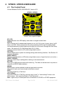
STWCS shown with
optional Easy Loader
Attachment
The Torque Wrench Calibration System is a high-precision machine designed to measure
and verify the calibration of hand torque tools. Considered one of the most flexible and userfriendly calibration systems available, LSI’s TWCS is offered in three models: a Standard
model (TWCS), Super model (STWCS), and an Ultra model (UTWCS). The TWCS model
operates with one load cell on a single unit. Select from five available torque capacities. The
STWCS features interchangeable smart torque cartridges. Switch load cells easily when a
different torque capacity is needed and enjoy the convenience! For flexibility without changing
out cartridges, the UTWCS allows up to three stationary load cells to test hand torque tools
of different capacities all on the same unit. Instantly change torque capacities with the push of
a button! Available torque cartridge capacities range from 3 in-lbs to 260 ft-lbs depending on
model. In all models, the load cells are protected during use by mechanical and software
stops to safeguard from overload damage. Each model includes three test modes: Manual
for needle-indicating tools, Peak for dial indicating or digital tools, and First Peak for click-type
torque tools. Unique to the industry, the STWCS and UTWCS both feature an on-screen
Calibration Assistant program to guide the user through the calibration steps and print a
certificate compliant with ISO 6789 standards. Connect to any parallel printer with the RS232
cable and adapter - a timesaving plus for the management of calibration verification and
ensuring torque tools are operating within the specified guidelines. The STWCS and UTWCS
also include a built-in computer that can access calibration, linearization, and a 1,800-test point
data logger. To allow for portability and ease of use, a rechargeable battery with an eight-hour
capacity is standard on the STWCS and UTWCS and is optional on the TWCS. An A/C
adapter provides auxiliary power and recharges the battery. LSI’s TWCS model series is
equipped for measuring in English and Metric units, including the Newton.
25 pin RS232
Interface
120V AC Adapter /
Battery Recharger
TWCS Series User Manual
Page 7 of 44
060-1000-0045-00E
1.1 Standard TWCS Features
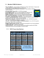
• Three Test Modes: Accommodates calibration for all types and classes of torque tools
(needle-indicating, dial/digital indicating, or click-type)
• Fourth Mode for Shunt Calibration Verification: Easily validate calibration
accuracy of tester
• Accuracy Better Than ± 0.4%: (10-100% of full scale)
• Push Button Zeroing: Zero out torque reading before each new test
• Backlit LED Display: Easily and comfortably view test results
• Digital Calibration: No tools required to calibrate from control panel
• NIST Traceable Calibration: In compliance with ISO 6789:2003(E)
• Clockwise / Counterclockwise Operation: Test in either direction
• Vertical / Horizontal Mounting: Horizontal mounting is standard; vertical mounting
possible without the Easy Loader Assembly installed
• Single Torque Capacity: Available in 100, 200, 500 in-lbs, 108 & 260 ft-lbs with a
1/4", 3/8”, or 1/2” drive (an adapter kit is available)
• Operates in Both English and Metric Unit Measurements: In-oz, in-lb, ft-lb, kg-mm,
kg-cm, kg-m, dN-m, N-mm, and N-M units
• Rugged Cast-Aluminum Housing: Heavy-duty and durable for use in any workspace
• 12-Month Warranty: Guaranteed satisfaction
• Optional Features: RS232 (printing) capability and portable operation with NiCad
rechargeable battery are both available as a factory option
1.1.1
TWCS Torque Specifications
TWCS – Torque Specifications
Capacity
100 in-lb
8 ft-lb
115 kg-cm
1.15 kg-M
11 N-M
200 in-lb
16 ft-lb
230 kg-cm
2.3 kg-M
22 N-M
500 in-lb
40 ft-lb
580 kg-cm
5.8 kg-M
60 N-M
TWCS Series User Manual
Resolution
0.02 in-lb
0.002 ft-lb
0.02kg-cm
0.0002 kg-M
0.002 N-M
0.05 in-lb
0.005 ft-lb
0.05 kg-cm
0.0005 kg-M
0.005 N-M
0.1 in-lb
0.01 ft-lb
0.1 kg-cm
0.001 kg-M
0.01 N-M
Capacity
108 ft-lb
1,300 in-lb
1,500 kg-cm
15 kg-M
145 N-M
260 ft-lb
3,100 in-lb
3,570 kg-cm
35 kg-M
350 N-M
Resolution
0.02 ft-lb
0.2 in-lb
0.2 kg-cm
0.002 kg-M
0.02 N-M
0.05 ft-lb
0.5 in-lb
0.5 kg-cm
0.005 kg-M
0.05 N-M
Accuracy is better
than ± 0.4% of reading
from 10-100% full scale
Page 8 of 44
060-1000-0045-00E
1.2 Super TWCS (STWCS) Features
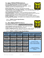
• All TWCS Standard Features, plus Electronics Upgrade
• Accuracy Better Than ± 0.2%: (10-100% of full scale)
• Separate Function for Shunt Calibration Verification: Validate
calibration accuracy with confidence in seconds
• Built-in Data Logger: Store up to 1,800 test points internally
• Interchangeable Torque Cartridge Capability: Order additional Smart
Torque Cartridges that can be swapped out easily – 3, 25, 100, 200, & 500 in-lb, 108 &
260 ft-lb capacities available (STWCS only)
• User Programmable Force Filter: Allows for increased accuracy of readings
• Calibration Assistant: Follow torque tool calibration steps with LED screen instructions
and print a calibration certificate ready for signature (“Easy Cal Report”)
• English / Metric Units: Same as TWCS except STWCS offers g-mm, not dN-m
• Printer Compatible: Connect to any parallel printer using the RS232 cable and adapter
• Rechargeable NiCad Battery: Go cordless for up to eight hours of continuous operation
1.2.1
STWCS Torque Specifications
See Section 1.3.1 below.
1.3 Ultra TWCS (UTWCS) Features
• All Standard STWCS Features: except interchangeable cartridges
• Three Stationary Load Cells on Single Tester: No cartridges to change
• Switch Between Load Cells in Seconds: Push a button and switch
between 200 in-lb, 108 or 260 ft-lb capacities instantly
• Custom Configure Load Cells: Special order one, two, or three load cells - 25, 100, 200
& 500 in-lb, 108 & 260 ft-lb torque capacities available as a factory option
1.3.1
STWCS / UTWCS Torque Specifications
STWCS / UTWCS Torque Specifications
Capacity
3 in-lb*
0.25 ft-lb*
3 kg-cm*
0.03 kg-M*
0.34 N-M*
25 in-lb
2 ft-lb
29 kg-cm
0.29 kg-M
2.8 N-M
100 in-lb
8 ft-lb
115 kg-cm
1.15 kg-M
11 N-M
Resolution
0.0002 in-lb
0.00002 ft-lb
0.0002 kg-cm
0.000002 kg-M
0.00002 N-M
0.002 in-lb
0.0002 ft-lb
0.002 kg-cm
0.00002 kg-M
0.0002 N-M
0.01 in-lb
0.001 ft-lb
0.01 kg-cm
0.0001 kg-M
0.001 N-M
TWCS Series User Manual
Capacity
200 in-lb
16 ft-lb
230 kg-cm
2.3 kg-M
22 N-M
500 in-lb
40 ft-lb
580 kg-cm
5.8 kg-M
60 N-M
108 ft-lb
1300 in-lb
1500 kg-cm
15 kg-M
145 N-M
Resolution
0.02 in-lb
0.002 ft-lb
0.02 kg-cm
0.0002 kg-M
0.002 N-M
0.05 in-lb
0.005 ft-lb
0.05 kg-cm
0.0005 kg-M
0.005 N-M
0.01 ft-lb
0.1 in-lb
0.1 kg-cm
0.001 kg-M
0.01 N-M
Page 9 of 44
Capacity
260 ft-lb
3100 in-lb
3570 kg-cm
35 kg-M
350 N-M
Resolution
0.02 ft-lb
0.2 in-lb
0.2 kg-cm
0.002 kg-M
0.02 N-M
Accuracy is better
Than ± 0.2% of reading
From 10-100% full scale
*Load Cell Capacity
not available for use with
UTWCS
060-1000-0045-00E
1.4 Optional Equipment
• Easy Loader Attachment: Easily mount any single arm torque wrench and test it the
same way every time, regardless of who the operator is (factory option)
• Power Tool Adapter Kit: Test powered torque tools such as power screwdrivers with
complete confidence and safety – includes adapters for 1/4”, 1/2", and 3/8” drives
• Drive Adapters: Test a variety of torque tools with 1/4”, 3/8”, 1/2”, or 3/4” adapters
• Inkjet Printer: Produce calibration certificates ready for signature on STWCS or UTWCS
(includes RS232 interface cable and adapter)
• RS232 to Parallel Printer Cable/Adaptor: Send data to any 8.5” x 11” or 4” parallel
printer and generate a customized report depending on series model
• Smart Torque Cartridges: Available for STWCS only in 3, 25, 100, 200, & 500 in-lbs,
108 & 260 ft-lbs
1.5 Tester Dimensions
Installment of the Easy Loader Attachment will vary for each model.
TWCS Series User Manual
Page 10 of 44
060-1000-0045-00E
2
GETTING STARTED
2.1 Unpacking
Your new TWCS model from LSI is shipped completely assembled. Once the shipping
container is opened, this User Manual is easily found with instructions to READ FIRST.
The TWCS testing unit and Easy Loader (if ordered) is bolted to the bottom of the shipping
container. Use care when removing from the packaging and protective poly bag to avoid
any damage. Other items ordered may be in their own carton(s) also bolted to the bottom
or inside of the shipping container. If possible, leave any cartons intact inside the container
and store for use later on. Occasionally, an item may be secured to the arm of the Easy
Loader if ordered.
2.2 Items Shipped
Locate the following items inside the shipping container:
• TWCS testing unit
• Power adapter / Battery charger
• Three 8 ½” X 11” white envelopes:
1 – User Manual
2 – Packing List
3 – Signed Calibration Report
• Optional equipment ordered
- If the Easy Loader Attachment was ordered, it will be assembled and already
connected to the testing unit (the pins that align the torque tool handle on the Easy
Loader and the small actuator wheel are in a small box with the power adapter).
• Interchangeable torque cartridges (STWCS only)
- Extra cartridges (if ordered) will be inside the shipping container in separate packaging
and fastened to the bottom or inside of the container. Within its packaging will be the
cartridge(s) attached by screws to a wood frame. The wood frame makes it easy to
safely package and ship back to LSI for recalibration and also provides a convenient
holder for the cartridge when not in use.
• Printer or larger equipment shipped separately
Check over the packing list and make sure all items listed were received. Keep items not
needed right away in a safe place. The TWCS unit may now be plugged into an 110V
power outlet using the adapter. Allow the battery to charge for eight hours before operating
on its own. (Note: The STWCS and UTWCS both have the battery installed as a standard
feature for portable use, an option on the TWCS.)
2.3 Installation
In choosing a location for the unit, a dry, non-humid, non-condensing environment, kept at
room temperature 20° C ± 5° C (68° F ± 9° F) is suggested. This should be a location that
also provides protection from debris or falling objects. Keep in mind accessibility to a
printer and power outlet depending on your model’s capabilities. When a relatively
permanent location has been chosen, fasten securely to a flat, vibration-free surface using
the mounting holes on the core unit. If vertical mounting is desired, the front panel will
need to be unscrewed and carefully turned for upright reading of the display. There are
wires attached to the circuit board on the back of the panel that need to stay in place.
Screw the panel in place once turned. Then, mount vertically to a flat, vibration-free
surface making sure the unit is level and perpendicularly positioned.
TWCS Series User Manual
Page 11 of 44
060-1000-0045-00E
While mounting is not required with the Easy Loader assembly installed, securing the core
unit is recommended to achieve consistent results. The core unit must be mounted
horizontally in this case. When using the TWCS at different locations for operation on its
battery (if applicable), continue to fasten it securely to a stable surface.
2.4 Using the Manual
2.4.1
Determine Model Being Used
TWCS: The software and instructions for this model are very different from the STWCS
or UTWCS and are covered separately starting at section 3.
STWCS or UTWCS: While these models each possess different features, they do have
identical control panels and the same underlying software. The two models are covered
together starting at section 4 with any differences in procedure noted.
2.4.2
General Startup
Turn on the testing unit by pressing [ON / CLEAR]. Commands referring to the keypad
will be shown in brackets [ ] throughout the manual. It is recommended to begin by
getting to know the TWCS starting with its control panel and go to the section that
pertains to the correct model. Familiarize yourself with how the buttons work. Then
follow the procedure set forth in the section of the manual that is applicable.
2.4.3
STWCS / UTWCS Users
Immediate torque tool testing may be done right from the initial screen that displays
after the machine is turned on without any further setup using the TWCS Calibration
Test Procedure in section 3.3. Torque readings will display and can be stored for
manual recording or printing. Press [STORE] to save and [SEND] to print. When
performing torque tool tests in this way, the display does not guide the user through the
test point adjustments and the results are printed as a list of readings that are not in a
report or certificate format. Use the worksheet found in section 4.8 or 4.9 to record the
data in an organized report format. Make copies of blank worksheets to keep on hand.
To perform torque tool testing to result in a concise calibration report summary or
certificate, follow the Quick start procedure explained below or follow the instructions in
section (4.7). Both describe data input procedures and torque tool testing that begins in
the User Setup and Cal Certificate menus and allows creation of a customized report or
certificate (Easy Cal Report).
The STWCS and UTWCS user will find a Quick Start to Torque Tool Testing in section
4.5 for their unit that may be followed to get to the actual torque tool testing and print a
calibration report or certificate without reading the entire manual. Although the Option
Menus section (4.6) contains valuable information about menu navigation and functions,
it is primarily designed to be informative rather than directional. Either choose to take
the time to absorb all features and functions or start immediately with the Quick start
instructions that refer to other sections of the manual as you go for direction.
Because the instructions for using the TWCS are less involved, a Quick Start section is
not included for that model.
TWCS Series User Manual
Page 12 of 44
060-1000-0045-00E
3
TWCS USER GUIDE
3.1 The Control Panel
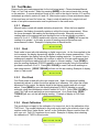
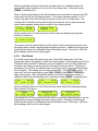
Current Software PN 050-1000-0010-00M, Version 6.0 – 6.8.
TWCS
Not an active button
on this model
Features Blue Splash Faceplate
[UNITS]
Use to choose unit of measurement between in-oz, in-lb, ft-lb, kg-mm, kg-cm, kg-M, dN-m,
N-mm, and N-M. Must correspond to the unit convention of the tool being tested.
[MODE]
Use to select the test mode that applies to the tool being tested. The three modes
available are: Manual for needle-indicating instruments, Peak for dial indicating or digital,
and First Peak for click-type tools.
There is also a fourth mode, Shunt, for checking the calibration of the TWCS.
[ZERO TORQUE]
Zero out current torque reading before starting a new test.
[ZERO ANGLE]
Not an active button on this model.
[OFF]
Turns the TWCS off.
[ON / CLEAR]
Turns the TWCS on and resets Peak and First Peak modes.
[SEND]
Use when a printout of current reading displayed is needed and TWCS is equipped with
RS232 capability. If not connected to a printer or not RS232 capable, “RS232 NOT
READY” appears on the LED screen.
When connected for printing and [SEND] is pressed, the printout shows the single reading
on the display (with a minus sign if performed counterclockwise) and the unit measurement
used. A series of test point measurements can then be printed one at a time on the same
page if desired for documentation.
TWCS Series User Manual
Page 13 of 44
060-1000-0045-00E
3.2 Test Modes
Determine the test mode appropriate for the tool being tested. Choose between Manual,
Peak, or First Peak modes. Select by pressing [MODE] on the control panel after turning
on the machine. If unsure which test mode to use, refer to the chart in section 4.10 and the
worksheets provided in section 4.8 and 4.9. Make extra copies of these worksheets ahead
of time and keep on hand for future use. Keep in mind all readings for a single tool and
series of test point measurements must be performed in the same mode.
3.2.1
Manual
Manual mode is used with needle-indicating torque tools. When the force applied
increases, the display dynamically updates to reflect the torque measurement. When
the force decreases, the reading on the display will recede. Manually record the
reading taken at the appropriate point during the test on the worksheet provided in
section 4.8 or 4.9. If RS232 capable with a printer connected, [SEND] will forward the
reading to be printed. In this way, a series of readings may be printed as each
measurement is taken. Example of display when in Manual mode:
3.2.2
49.18 in-lb
Peak
Peak mode is used with dial-indicating or digital torque tools. As the force applied to the
tool increases, the display dynamically adjusts to reflect the torque measurement. If the
torque subsides, the display locks at the highest reading captured. If a greater force is
subsequently applied, the display will continue to adjust to a torque measurement that
exceeds the previous reading but will not adjust to a lesser reading. Press [SEND] to
print the reading displayed (if RS232 capable) or record manually using the worksheet
provided in section 4.8 or 4.9. Press [ON / CLEAR] to reset Peak mode and begin a
new measurement. [ZERO TORQUE] will zero out the last reading. Example of display
when in Peak mode:
pk
3.2.3
49.18 in-lb
First Peak
First Peak mode is used with click-type torque tools. Again, the displayed reading
dynamically adjusts to reflect the torque applied as it increases. But, when the torque
decreases for an instant, the display stops at the highest reading and will no longer
adjust. Press [SEND] to print the reading displayed (if RS232 capable) or record
manually using the worksheet provided in section 4.8 or 4.9. Press [ON / CLEAR] to
reset First Peak mode and begin a new measurement. As in Peak mode, [ZERO
TORQUE] will zero out the last display reading. Example of display in First Peak
mode:
fpk
3.2.4
49.18^in-lb
Shunt Calibration
This mode does not apply to the calibration of a torque tool, but to the calibration of the
TWCS unit. The number displayed in this mode must equal or be relatively close to the
number under Shunt Value shown “as left” on the Calibration Report received from LSI
with your unit. Call LSI if numbers do not match. Example of display when checking
the calibration of TWCS in Shunt mode:
shn 177.35 in-lb
TWCS Series User Manual
Page 14 of 44
060-1000-0045-00E
3.3 TWCS Calibration Test Procedure
3.3.1
Prerequisites
A TWCS properly installed for testing torque instruments must be used. The torque
cartridge capacity must be greater than the highest capacity torque tool that will be
tested on it. If it is not, there is danger of overloading the torque cartridge.
3.3.2
Connect the Printer
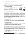
If the TWCS is RS232 capable (optional) with a 25-pin
connector on the back of unit, printing may be done on a
parallel printer. Use an LSI RS232 interface cable to
parallel adapter to enable this function. After connecting
the cables, turn on the TWCS and printer.
3.3.3
Pre-Calibration Worksheet
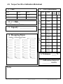
Use the Calibration Data Template and/or Pre-Calibration Worksheet found in section
4.8 and 4.9, respectively, to determine classification options for torque tool testing,
record test point data, and provide certification documentation. Keep copies of these
forms on hand for future use. Refer to the chart in section 4.10 for information on Tool
Types and Classes to complete the worksheets and select the correct test mode and
acceptable tolerance. Use the information collected on the forms to complete the
torque tool testing process and perform the correct number of test points and record the
measurements of each. When determining tool type and class, look for how the tool
adjusts. For example, does it operate with a graduated measurement scale or is it
adjusted using a digital display?
3.3.4
Unit Selection
Press [UNITS] until the desired unit of measurement is displayed. Choose from in-oz,
in-lb, ft-lb, N-m, dN-m, N-mm, kg-m, kg-cm, and kg-mm. The unit convention must
match that of the torque tool.
3.3.5
Select Test Mode
Press [MODE] to select Manual, Peak, or First Peak mode. Refer to the Pre-Calibration
worksheet and Tool Types and Classes chart in this manual for assistance. See section
3.2 for information on each test mode and its respective display data.
3.3.6
Exercise Torque Tool
Before actual testing, type 2 tools must be exercised at full capacity at least five times.
The torque tool must turn in the direction being tested, and torque indication must be
triggered (i.e., click-type wrenches must “click” five times). If the tool being tested is
used both clockwise and counterclockwise, also test it both ways and be sure to note.
3.3.7
Zero Out Torque
Press [ZERO TORQUE] to clear the last torque reading before each new test.
3.3.8
Mount Torque Tool
Without Easy Loader Attachment installed: Adjust the torque tool to the test point mark
to be measured and place the torque tool onto the TWCS. Its position should be level
to the tester and centered. Make sure the display reads zero before testing.
TWCS Series User Manual
Page 15 of 44
060-1000-0045-00E
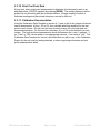
Easy Loader Attachment installed: Adjust the tool to the test point mark to be measured
and load the torque tool onto the TWCS with the arm of the wrench extending parallel to
the Easy Loader Attachment. Loosen the quick-release lever and adjust the slide so the
wrench handle is supported in the middle. Adjust the actuator wheel to give the
maximum amount of travel in the direction of the test. Insert the stop-pins so the
wrench is contained on both sides, and tighten the quick-release lever to hold the slide
in place. The stop-pins should be on either side of the wrench handle such that when
the tool reaches its click point, the stop-pins meet as close as possible in the middle of
the handle. This center point on the tool handle is identified by a line or marking. The
length of some torque tools will change after adjusting to the next test point mark and
will require adjustment of the slide on the Easy Loader for proper positioning.
Stop-Pins
Slide
Quick Release
Lever
Actuator Wheel
UTWCS shown with Easy
Loader Attachment for
illustration purposes
3.3.9
Test Torque Tool
Refer to the Force Application diagrams in section 5, Technique for Good
Measurement, for recommended position and movement to use when testing. Record
the test point reading, press [ON / CLEAR] and then [ZERO TORQUE]. Repeat the
steps from 3.3.7 to 3.3.9 for the required number of times determined necessary for
each test point. Do not record test point measurements that were not performed in
accordance with recommended procedures – simply redo the test.
Note: As stated earlier, if the tool being tested is used both clockwise and counterclockwise, it should be tested both ways. The calibration can be different in each
direction depending on usage. Make sure documentation of calibration testing shows
CW or CCW for the testing direction.
TWCS Series User Manual
Page 16 of 44
060-1000-0045-00E
3.3.10 Print Test Point Data
At any time, when a test point measurement is displayed, the data can be sent to an
attached printer (if RS232 capable) by pressing [SEND]. The reading displayed will be
printed on one line along with the unit measurement. A single reading or series of
individual readings may be printed to kept as a record for that tool.
3.3.11 Calibration Documentation
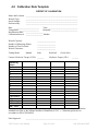
Using the Calibration Data Template in section 4.7, pass or fail for the torque tool tested
can be documented. At the + 4% or 6% line, calculate what that would be for the test
point in each column. On the next two lines for each column, fill in the high and low
measurements taken. On the next line, calculate – 4% or 6% for the test point in each
column. The high and low measurements should fall between the + and – numbers. If
so, “Pass” or “OK” can be written in the appropriate columns. If not, write in “Fail.” The
Calibration Data Template for the tool, should be filled out with a copy of the Calibration
Report for the unit used for testing attached, or other supporting information and test
point measurements taken.
TWCS Series User Manual
Page 17 of 44
060-1000-0045-00E
4
STWCS / UTWCS USER GUIDE
4.1 The Control Panel
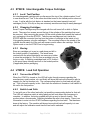
Current Software PN 050-1000-0005-00J, Version 4.22.
STWCS / UTWCS
Features Yellow Splash Faceplate
[F1] [F2]
Make selections from LED display; enter data or navigate screen fields.
[UNITS]
Use to choose unit of measurement between in-oz, in-lb, ft-lb, g-mm, kg-mm, kg-cm, kg-M,
N-mm, and N-M. Must correspond to the unit convention of the torque tool being tested.
Unit measurements not being used may be edited out of this menu through the User Setup
menu. See section 4.6.5 (User Setup) and 4.6.5.4 (Units).
Performs reverse direction of [F1] when using Option menus.
[OPTION]
Initiates display menu system for entering settings and selecting functions. See Section 4.6
for more information.
[ZERO ANGLE]
Performs reverse direction of [F2] when using Option menus. (Angle function is not active.)
[ZERO TORQUE]
Zero out current torque reading before starting a new measurement.
[STORE]
Store up to 2,000 test points with built-in data log. The data can be later sent to a printer or
computer via RS232 cable interface.
[SEND]
RS232 output can be enabled to send test point data to a printer.
Also used to back out of menu levels in the Option menus.
[OFF]
Turns the STWCS or UTWCS off.
[ON /CLEAR]
Turns the STWCS or UTWCS on and acts as an “enter” or “save settings” button in the
Option menus. Also resets the Peak or First Peak mode.
Note: Lights at top of control panel are not functional on STWCS or UTWCS equipment.
TWCS Series User Manual
Page 18 of 44
060-1000-0045-00E
4.2 Test Modes
Determine the test mode appropriate for the tool being tested. Select the test mode by
pressing [MODE] until desired mode is displayed. Each of the test modes and how they
work are described below with display screens referenced. Mode can be selected and
used at the initial screen after the machine is turned on, or in the Cal Certificate menu when
Start is selected. (See section 4.6.1). If unsure what mode should be used for testing a
particular torque tool, a tool classification chart is located in section 4.10. This chart is used
in conjunction with the worksheets before it. Keep in mind that all readings for a single tool
and series of test point measurements must be performed in the same mode.
4.2.1
Manual
Manual mode is used with needle-indicating torque tools. As the force applied to the
tool increases, the display dynamically adjusts to reflect the amount of torque
measured. When the force applied recedes, the reading will adjust downward.
Because of the continual reading adjustment, the actual reading must be stored during
the application of torque force. Press [ZERO TORQUE] between readings and
remember to change the test point mark on the tool being tested when the test point
changes. After all readings are stored for each test point, a report will be generated as
output to a printer if specified to do so. Otherwise, press [SEND] to forward to the
printer.
When in Manual mode from Cal Certificate menu and Start is selected, the LED screen
will look like the first example below with the top line flashing between “1st Pt. 20.00”
and “Test 1/05.” The “T” in the bottom left corner means the unit is in Manual mode. A
reading is now ready to be taken for the first test point, at the 20 in-lb mark of tool
capacity, and will be test number 1 of 5 to be taken. The second screen shows a test
reading; pressing [STORE] as described above results in the third LED screen below
stating the test number being stored.
1st Pt.
T
0.00
20.00
in lb
T
Test 1/05
49.85 in lb
Storing Test
Number:
1
Screen displayed when in Manual mode from initial screen and beginning testing after
machine is turned on:
T
0.00
in lb
This screen does not show at what point the series of test point measurements is, but
the display when storing the reading works the same. Readings stored here may be
printed using [SEND] but will not be in a Calibration Report/Certificate format. Stored
readings will not need to be cleared for each tool tested. The data logger will accept up
to 1,800 test point readings when stored this way.
4.2.2
Peak
Peak mode is used with dial-indicating or digital torque tools. As the force applied to the
tool increases, the display dynamically adjusts to reflect the torque measurement. If the
force subsides, the display locks at the highest torque reading captured. If a greater
force is subsequently applied, the measurement displayed will adjust to a torque
measurement that exceeds the previous reading but will not adjust to a lesser reading.
Press [STORE] to save reading. To reset the Peak mode display, press [ON / CLEAR],
then [ZERO TORQUE] to begin a new test point measurement.
TWCS Series User Manual
Page 19 of 44
060-1000-0045-00E
After the specified number of test points has been stored, a calibration report will
automatically print if specified to do so in the User Setup menu. Otherwise, press
[SEND] to manually print.
When in Peak mode starting at the Cal Certificate menu and Start is selected, the LED
screen will look like the first example below. The screen indicates reading 1 of 5 is
ready to be taken at the 20 in-lb test point mark and the unit is in Peak mode. The
reading will be viewable until stored following the directions above, then the second
screen below appears stating which number of test is being stored.
1/05,
P 0.00
20.00
in lb
Storing Test
Number:
1
Screen display when in Peak mode from initial screen and beginning testing after
machine is turned on:
P
0.00
in lb
This screen does not show at what point the series of test point measurements is, but
the display when storing a reading works the same as above. Readings stored may be
printed but will not be in a Calibration Report/Certificate format. Store up to 1,800 test
point readings with the built-in data logger.
4.2.3
First Peak
First Peak is used with click-type torque tools. Much like Peak mode, First Peak
dynamically adjusts the display to reflect the torque applied. When beginning at the Cal
Certificate menu and Start is selected, as force is applied to the tool being tested and
increases, the display moves through the first series of screens below. If the torque
decreases for an instant, the display stops at the highest-read torque and indicates the
test is finished. The reading can no longer be adjusted. Press [STORE] to save. To
reset the First Peak mode display, press [ON / CLEAR], then [ZERO TORQUE] to
begin testing again. After the specified number of test points has been stored, a
calibration report will automatically print if specified or press [SEND] to manually print.
1/05,
50.00
Pr
0.00 in lb
Factory Setup
1/05,
50.00
Pm
24.40 in lb
Factory Setup
1/05,
50.00
Pf 48.98 in lb
Factory Setup
Ready
Pr
0.00 in lb
Factory Setup
Measuring
Pm
24.40 in lb
Factory Setup
Finished
Pf 48.98 in lb
Factory Setup
Screens displayed when in First Peak mode from initial screen and beginning testing
after machine is turned on:
The screens do not show at what point the series of test point measurements is, but the
display when storing a reading works the same as above. Readings stored may be
printed but will not be in a Calibration Report/Certificate format. Store up to 1,800 test
point readings with the built-in data logger.
TWCS Series User Manual
Page 20 of 44
060-1000-0045-00E
4.3 STWCS: Interchangeable Torque Cartridges
4.3.1
Lock / Test Position
An interchangeable cartridge with a collar around the top of the cylinder marked “Lock”
in one direction and “Test” in the other should be turned to the locked position when not
in use. A collar with the lock feature is standard on the lowest capacity load cell
cartridges (3 in-lb, 25 in-lb) as they are extremely sensitive and may be easily damaged.
4.3.2
Changing Cartridges
Smart Torque Cartridges may be changed with the unit turned off or while in Option
mode. There are four screws around the top of the cylinder of the cartridge that must
be removed. After removing the screws, lift the entire cylinder that houses the load cell
out, unplugging it from the STWCS. Take the new cartridge and set it inside the
STWCS with the connector lined up from the bottom of cartridge to the inside of unit.
Using gentle pressure, plug the cartridge in. The mounting holes on the outside of the
cylinder should match up to the unit and screws used to secure the cartridge. Exit the
Option mode or turn the STWCS on to begin testing.
4.3.3
Storing
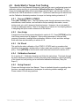
Store any cartridge not in use in a safe place and left in
the locked position (if applicable). The wood frame
received with the extra cartridge(s) can serve as a holder
to store the cartridge(s). Do not store a cartridge lying on
its top or side. If shipping a cartridge back to LSI, screw it
to the wood frame securely and turn to the locked position
(if applicable) before packaging.
4.4 UTWCS: Load Cell Operation
4.4.1
Turn on the UTWCS
When the UTWCS is turned on, the LED will cycle through screens regarding the
manufacturer, serial number, etc. and finally will show the load cell information with its
capacity for the first location only. The corresponding button by that load cell will light
up. This is the cell currently in use. Each time the machine is turned on it will default to
the cell in the first position.
4.4.2
Switch Load Cells
To test with one of the other load cells, just push the corresponding button for that cell.
The LED will indicate a switch is taking place and will note when the changeover is
complete. In addition, the button pushed will light up next to the cell chosen. This
process takes a few seconds. Switching between the cells is that simple. There is no
information to enter into the UTWCS software regarding the load cells. That has been
done at the factory. The machine will always know which load cell capacity is in use
and will adjust the calibration each time the load cell is switched.
TWCS Series User Manual
Page 21 of 44
060-1000-0045-00E
4.5
Quick Start to Torque Tool Testing
This section of the User Manual is designed to fast track the user to performing torque tool
calibration testing resulting in a customized Calibration Report or Certificate. To start
torque tool testing right away without generating a specific report, just turn the machine on
and follow the TWCS instructions in section 3.3. If preferred, read through the manual and
use the Calibration Assistant procedure for torque tool testing starting at section 4.7.
4.5.1
Turn on STWCS / UTWCS
Press [ON / CLEAR] to start. The LED display cycles through various screens listing
manufacturer, serial number, load cell data or torque cartridge information, current
testing mode, etc. until it stops at a blank test screen. However, it is not yet ready for
torque tool calibration testing. Refer to the beginning of section 4.6 for helpful guidance
in navigating the Option menus referenced in this section.
4.5.2
User Setup
Complete the User Setup process described in section 4.6.5. Press [OPTION] until the
User Setup menu shown is displayed. Enter printing parameters, time and date,
company information, backlight timer preference, direction of test, and other settings.
Enter each item as instructed up to section 4.6.6.
4.5.3
Cal Check
This verifies the shunt calibration of the STWCS / UTWCS and is a procedure that
should be done regularly, whether daily or before each use according to your company
policy. Press [OPTION] to find this menu and follow the instructions in section 4.6.4.
4.5.4
Calibration Assistant
Go to section 4.7 - Calibration Assistant and follow the instructions. This leads through
the entire calibration procedure, including any setup and preparation, the actual testing
of the torque tool, and printing out a customized calibration certificate (“Easy Cal
Report”).
4.5.5
Going Forward
Please read through entire User Manual. There is detailed information regarding other
functions, care and maintenance, techniques for achieving reliable readings, etc.
Please contact LSI with any questions.
TWCS Series User Manual
Page 22 of 44
060-1000-0045-00E
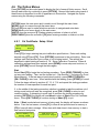
4.6 The Option Menus
Press [OPTION] on the control panel to display the first of several Option menus. Scroll
through each menu by continuing to press [OPTION]. General information about each of
these menus is described in order of appearance in this section. Navigate the Option
menus using the following commands:
[OPTION] starts the main menu and is used to scroll through the menu items
[MODE] scrolls in reverse through the menu items
[F1] and [F2] are used to make selections and also to navigate and enter data
[SEND] backs out of menu levels to the main menu
[UNITS] does the reverse of [F1] when entering numbers or letters in a field
[ZERO ANGLE] does the reverse of [F2] when entering numbers or letters in a field
4.6.1
Cal Certificate: Setup / Start
Cal Certificate
Setup
Start
Setup
Press [F1] to begin entering test point calibration specifications. Enter each setting
desired using [F1] and [F2]. Press [OPTION] to advance to the next setting. Enter new
settings each time another type or class of tool is being tested. The settings are
described in detail starting at section 4.7.8 - Setup Calibration Procedure. When all
calibration settings have been entered, press [SEND] to save setup and continue, or
press [OPTION] to scroll through the items again.
Start
Select Start [F2] to begin the tool testing procedure. Press [ZERO TORQUE] to clear
out any prior reading. Then, test the torque tool. (See Section 5 -Technique for Good
Measurement). If the test was not performed correctly, press [ZERO TORQUE] or
[ON / CLEAR] to start over. When satisfied with the reading, press [STORE] to record.
Follow the steps outlined in sections 4.7.12 - 4.7.14 and repeat this testing procedure
the number of times specified for each test point.
If, in the middle of the testing procedure a button is pushed to take the machine out of
testing mode before all tests are completed, press [ON / CLEAR] to return to and
continue testing. If attempting to scroll back to continue the testing procedure by
pressing [OPTION], the display will read Abort in place of Start at the Cal Certificate
menu. Press [ON / CLEAR] to continue testing or Abort [F2] to quit.
Note: If Start is selected and memory is being used, the display will stream as shown
below. From the last screen, choose [F1] to clear all test points stored in memory or
[F2] to keep all data in storage. When done with data stored, clear memory to start a
new series of test points.
Store Memory is
being used
TWCS Series User Manual
and must be
cleared to begin
Page 23 of 44
Keep data?
Clear
Keep
060-1000-0045-00E
4.6.2
Store
Option: Store / EndPrint
Option
EndPrint
Store
From this selection, view stored test point data, clear a single test point from memory, or
clear all test points from memory. Scroll through test points using [F1] or [F2]. To
select a test point as in the first example below, press [OPTION]. The display will read
like the second example below. Press [F1] to clear that test point or press [OPTION]
again and the third example below will be displayed. Here, press [F1] to clear all test
points from memory or [OPTION] to return to the test point reading. Unless [F1] is used
to clear any test points, they will be saved.
# 10
n/a
15.16
deg
in+
Clear Mem
Now
10
Clear All Memory
Now
EndPrint
This selection ends the printout in progress and prints out the statistical summary.
4.6.3
Option: Offset / Power
Option
Offset
Power
Tor. Off.(in lb)
nxt 000.00
+
Offset
Power
Offset
A torque offset may be entered using this selection [F1]. This means when [ZERO
TORQUE] is pressed, the torque displayed will adjust to the offset specified as opposed
to zero. To do this, press [OPTION] until display reads Tor. Off. Advance the cursor in
the field underlined above using [F1] or [UNITS] to backspace. Change the values
using [F2] or [ZERO ANGLE]. When finished, press [ON / CLEAR] to accept and exit
or [SEND] to return to the previous menu. The angle offset is not active for TWCS
models and should be ignored.
Power
This option has only two choices. They are Stay On [F1] or Off [F2].
4.6.4
Option: Cal check
Option
Cal Check
Select Shunt
Load Cell Panel
S -172.96
T -172.96
in lb
in lb
Cal Check
Use this function to check the shunt calibration number. This can be done as often as
daily or before each use. It is recommended to follow your company policy for
determining frequency of calibration verification. When Cal Check is selected using
[F1], the options displayed are Load Cell or Panel. Press [F1] to choose Load Cell
and two numbers will display following instruction cues. The numbers should be
negative and match or be relatively close to each other as shown in the third LED
example above. The top number is the shunt calibration reading established at the
factory during calibration and recorded in memory. To exit when finished comparing the
numbers, press [ON / CLEAR]. If the numbers do not closely match, call LSI.
TWCS Series User Manual
Page 24 of 44
060-1000-0045-00E
4.6.5
Option: User Setup
Option
User Setup
Enter Passcode
or press Option
User Setup
To enter the main User Setup menu press [F1]. The display will ask for a pass code or
press [OPTION] to continue to the next Option menu. To enter pass code, press
[UNITS], [SEND], and [F1] in sequence.
There are several submenus for entering printing parameters, time and date, company
information, backlight timer preference, direction of testing, etc. Press [OPTION] to
move to each menu.
4.6.5.1
User Setup: RS232 / Power
User Setup
RS232
Power
RS232
By selecting RS232 [F1], the communication can be set up to send raw data or a report to
equipment such as a data logger or printer. The following is a list of data format options to
be defined within the RS232 menu before data can be sent and printed. Next to each item
in the first column are the choices available. Use [F1] or [F2] to select or scroll to the choice
desired. Press [OPTION] to move to the next item once selection or input has been made.
Output Format:
Print Report:
Print Out Format:
Printer Format:
Printer Format:
Printer ch, width
Printer Protocol*
Printer Baud Rate*
Paper Type
Lines per Page
Dbl Wdth On/Off
Define Dbl Wdth
Define in
Report
Data
Yes
No
Standard
Full Stats
Print Heading
No Heading
Print Summary
No Summary
80, Single
80, Double
Hardware, None, Delay .01 sec, Delay .025 sec, Delay .05 sec
9600, 19200, 1200, 2400, 4800
Plain Paper
Roll Feed
[F1] advance to next digit [F2] increment digit
Oki – 1F/1E, Epson – OE/14, Other
On Str
Off Str
[F1] advance to next digit [F2] increment digit
Decimal
Hex
[F1] advance to next digit [F2] increment digit
*Factory setup for Printer Protocol is Hardware; for Printer Baud Rate, 9600.
When finished, press [ON / CLEAR] to accept.
TWCS Series User Manual
Page 25 of 44
060-1000-0045-00E
Power Time-out
next
00:00
+
Power
Select Power [F2] to set or turn off the timer for auto shut-off feature. The timer is displayed
in HH:MM format and starts each time a button is pressed. When the machine is idle for the
time set, it will turn off automatically. To set the timer, move the cursor [F1] to the field to be
modified (underlined in LED example above) and use [F2] to change each value. Enter
99:99 to turn off the Power Time-out feature. When finished, press [SEND] to save and
return to the previous menu. Press [OPTION] to move to the next User Setup menu.
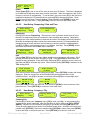
4.6.5.2
User Setup: Dampening / Date and Time
User Setup
Dampening
Date
Peak Dampening
None
+
Dampening
Press [F1] to choose Dampening. This feature is used to provide varied levels of noise
reduction or dampening that may contribute to false readings when testing. Dampening
averages the force measurements to eliminate the noise in the display caused by vibration.
Because the dampening feature slows the measurement process it is recommended the
dampening be set at the minimum level necessary to achieve a stable, readable display.
Use [F1] or [F2] to select between None, Low, Medium, and High. Press [SEND] to save
and return to the menu where Date may be selected.
User Setup
Dampening
Date
-
Date Format
MM/DD/YY
+
MM:DD:YY
Next 02 01 07 +
Date
Choose Date [F2] from the first menu above and the next menu shown will appear. Scroll
through the three format choices using [F1] or [F2]. Press [OPTION] to select when the
desired format is displayed. Enter the correct date using [F1] to advance cursor to the next
digit field and [F2] to increase digit value. When finished, press [OPTION] to advance to the
Time setting menu.
Time Format
- 12 Hour a/pm +
-
Time Format
24 Hour
+
View the two format choices above using [F1] or [F2]. Press [OPTION] to select the format
displayed. Enter the current time in the corresponding screen shown below in the
underlined fields. Use [F1] to advance to next digit field and [F2] to increase digit value.
HH:MM a/pm
next 12:19 p
+
HH:MM
next 12:19
+
Press [OPTION] to review the Date and Time entries or [SEND] to save and return to the
previous menu. Press [OPTION] to continue to next menu item.
4.6.5.3
User Setup: Company / City
User Setup
Company
City
Company Name 1/4
next ________ +
City Name 1/4
next ________ +
Company/City
Choose [F1] to enter your Company name, [F2] to enter your City. In the corresponding
screens above where underlined, enter the first letter or digit in field using [F2] or [ZERO
ANGLE]. Advance to next character using [F1] or go back a field using [UNITS] to edit.
There are eight characters on each of four possible screen lines. Advance to the next line if
needed using [OPTION]. Review the entries using [OPTION] or when done press [SEND]
to save and return to the previous menu. Press [OPTION] to continue to next item.
TWCS Series User Manual
Page 26 of 44
060-1000-0045-00E
4.6.5.4
User Setup: Backlight / Units
User Setup
Backlight Units
Light Time-out
Next
00:00
+
Sleeping, press
a key to wake up
Backlight
Choose Backlight [F1] to enter Backlight Time-out setting in HH:MM format. Advance
between the digit fields underlined above using [F1] and [UNITS]. Adjust digit values using
[F2] and [ZERO ANGLE]. When finished, press [SEND] to save and return to the previous
menu. If tester is not used for the amount of time entered, it will go to sleep. The display
will read like the third LED sample above, except the backlight will be dark. Enter 99:99 to
turn off Backlight Time-out feature.
-
Units Used
in lb used
+
Units Used
-No in lb units+
Units
Choose Units [F2] to remove any unit measurements that will not be needed from the
[UNITS] selection menu. Scroll through unit measurements using [OPTION]. Units listed
will show as used if included as a menu selection. See first display example above. When
removed – [F1], units will be listed as not available as in the next display example. If a unit
has been removed, it may be added back at any time through this User Setup menu by
pressing + [F2] when unit needed is displayed. When done, press [SEND] to save and
return to the previous menu. Press [OPTION] to continue to next User Setup menu item.
4.6.5.5
User Setup: 1st Peak / Filter
User Setup
1st Peak Filter
First Peak Drop
nxt 50x0.020000+
1st Peak
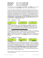
Choose [F1] to enter First Peak Drop value. This value is used in the calibration testing of
click-type torque tools. Enter the desired value in the fields shown underlined above using
[F1] and [F2]. Press [SEND] to save and return to the previous menu. Press [OPTION] to
continue to next menu item.
When testing a click-type torque tool the force applied increases over time; however, just
before the “click,” the force applied decreases and a reading is measured. This point
between the highest force applied and the measurement read is the First Peak Drop. The
value shown in the second LED example above compensates for the reduced force just
before the reading. The value of 50 is the default fixed at the factory and has been found to
be the most reliable for achieving accurate results. If the tester is capturing the force too
late, the first peak drop may need to be set at a smaller value.
User Setup
1st Peak Filter
-
Filtering
None
+
Display Filter
Yes
+
Filter
Filtering is the first submenu under Filter [F2]. Using [F1] or [F2] choose between None,
Low, Medium, High, User #1, User #2, User #3, and User #4. Once the desired selection is
displayed, press [OPTION]. Toggle between Yes and No using [F1] or [F2] to display filter.
Press [OPTION] to select. The next four submenus are accessed using the [OPTION] key
after each. The directions follow on the next page along with filtering information.
TWCS Series User Manual
Page 27 of 44
060-1000-0045-00E
Dampening (Kd)
Dampen Min (M)
Decay Rate (C)
Recovery (R)
Enter % value using [F1] and [F2]
Enter % value using [F1] and [F2]
Enter % value using [F1] and [F2]
Enter value using [F1] and [F2]
To review entries made under Filtering press [OPTION]. Press [SEND] to save and return
to the previous menu. Press [OPTION] to continue to next User Setup menu item.
During normal operation the display shows some number of discrete force values every
second. These values can be thought of as the value being displayed and the next value to
be displayed. When the two values are subtracted from each other, the result is an error.
Filtering works by multiplying this error by a percentage and then adding that partial error to
the displayed value and displaying that as the new value. The percentage that the error is
multiplied by is Kd. Kd changes over time. While the force is stable, Kd decreases from
the Kd entered in the User Setup menu to the Dampen Min (M) value at a rate defined by
the Decay Rate (C). The Recovery (R) value is used to increase Kd when the force starts
to change based on duration and amount of change. The Kd value will be shown as it
changes over time when Display Filter is chosen.
4.6.5.6
User Setup: + / - Rule
User Setup
+/- Rule
+/- Torque Rule
- CCW Positive +
+/- Angle Rule
- CW Positive +
+ / - Rule
Choose +/- Rule using [F1]. Go to +/- Torque Rule using [OPTION]. (Angle Rule not
active on this model.) Select CW Positive or CCW Positive using [F1] or [F2]. CW =
Clockwise, CCW = Counterclockwise. This corresponds to the direction the tool is being
tested on the unit and displays the readings taken in the direction selected as positive
numbers. This setting may need to be changed frequently.
When performing tests to result in a Calibration Certificate for signature, it is important that
the readings are positive numbers. If performing the test in Clockwise direction, choose CW
Positive - Counterclockwise, CCW positive. If negative readings are recorded, the
Calibration Certificate will always produce a FAIL test for the torque tool. When done, press
[SEND] to return to the previous menu. Press [SEND] again to return to the User Setup
main menu.
4.6.5.7
User Setup: I / O Polarity
User Setup
I/O Polarity
Input
2 Pol.
> HHHHXXXXXXXX +
Output
6 Pol.
> XXXXHHHHHHHH +
I / O Polarity
+/- Rule
+/- Rule
+/- Rule
The I / O Polarity menu accesses a setup feature for users who need to use the external
inputs and outputs on the tester with certain auxiliary equipment. To select, press [F1] and
the second display example shown above appears. Press [F1] to advance through the “H”
fields underlined. Press [F2] to change any “H” to “L”. These 4 fields represent polarities of
2, 3, 4 and 5, respectively, from left to right and define the active voltage level for those
polarities as high or low. Press [OPTION] to advance to the third display example shown
above. This screen operates the same: Press [F1] to advance through the “H” fields
underlined and press [F2] to change any “H” to “L”. These eight fields represent polarities
of 6, 7, 8, 9, 10, 11, 12 and 13 from left to right.
This menu feature is not commonly used. Users wanting to use this feature should contact
LSI for further instruction.
TWCS Series User Manual
Page 28 of 44
060-1000-0045-00E
4.6.5.8
User Setup: Cal. Info
User Setup
Cal. Info
Cal.
+/-Info
Rule
Use this menu to enter calibration information. This will store the name of the company that
performed the last calibration of the tester, the calibrating company’s phone number, when
calibration was done, and when the tester is due for its next calibration. A new tester will
show Larson Systems Inc information.
The display screens below show the 10 data entry screens available for tester calibration
information. There are eight fields or characters that may be entered on each screen in the
underlined areas as shown. Navigate to each character field by pressing [F1] and backup
using [UNITS]. Press [F2] to advance through and make selections from the alphabet in
lower case, characters, numerals, spaces, and the alphabet in upper case. To navigate
through selections in reverse, press [ZERO ANGLE]. Once finished with a single screen,
advance to the next screen by pressing [OPTION]. To go back to a screen, press [MODE].
The first four screens are used to enter the name of the calibrating company:
Calibrated by
next Larson S
1
+
Calibrated by
next ystems I
2
+
Calibrated by
next nc.
3
+
The next four represent the calibrating company’s phone number.
+/- Rule
+/- Rule
+/- Rule
Phone Number 1/4
Phone Number 2/4
Phone Number 3/4
next 763-780- +
next 2131
+
next
+
Calibrated by
next
+/- Rule
Phone Number 4/4
next
+
The last two screens are for the date calibrated and the date recalibration is due.
+/- Rule
+/- Rule
+/+/- Rule
DateRule
Calibrated
Calibration Due
nxt 04 17 07 +
nxt 04 17 08 +
This
will appear
on the
Report of Calibration certificate generated for a torque
+/- information
Rule
+/Rule
tool being tested.
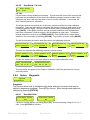
4.6.6
Option: Diagnostic
Option
Diagnostic
Diagnostic
This function allows user to troubleshoot the tester and print out reports that may be
helpful in diagnosing a problem. Press [F1] to choose. Move through each diagnostic
category by pressing [OPTION].
4.6.6.1
View Batt Volts
View Batt Volts
Yes
+
View Batt Volts
No
+
Choose to view the battery volts using [F1] or [F2]. The best operating voltage is 6.2 to 7.0
volts. Press [OPTION] to continue.
TWCS Series User Manual
Page 29 of 44
4
+
060-1000-0045-00E
4.6.6.2
Keypad Check
Perf Keypad Chck
Press Clear to
Press any key
Now
exit Keypad Chck
Press [F1] to check the keypad. The next screen above will flash and stop at “Press any
key.” Check the keys by pressing each one and leave [ON / CLEAR] till last to exit. As
each key is pressed the display should show its name – if not, the keypad is not functioning
properly. After exiting, press [OPTION] to go to next diagnostic menu.
4.6.6.3
Screen Check
Press Clear to
Perf Screen Chck
exit Screen Chck
Now
Press [F1] to check the LED screen. The next screen above will flash and the LED cursor
will start to cycle through each of the fields. When satisfied that each field is operating
correctly, press [ON / CLEAR] to exit, and then [OPTION] to go to next diagnostic menu.
4.6.6.4
Output Diag Test
Output Diag Test
nxt
1 off tgl
Using [F1], scroll through the numbers 1,2,3, or 4 and make selection. [F2] toggles
between on and off. Press [OPTION] to go to next diagnostic menu. The standard tester
does not include the outputs affected by these selections.
4.6.6.5
RS232 Protocols
RS232 Protocols
9600, Hardware
No selection needed. Information only listing the fixed protocols set at the factory.
4.6.6.6
RS232 – Report On
RS232-Report On
Heading Summary
No selection needed. Information only.
4.6.6.7
Check RS232 Port
Perf RS232 Check
Trying to send
RS232 Port Sent
Now
info with RS232
info OK
Press [F1] to check the RS232 Port connection. If printer is not connected, a loop back
device may be attached to perform the check. When the check is performed, “Greetings
User” will appear on the display. If connected to a printer and the RS232 port checks out, a
printout is generated. “Greetings user. The RS232 port is working OK. Have a nice day.”
4.6.6.8
Display Processor Data
16MHz processor
with 64Kb RAM
No selection needed. Information only.
4.6.6.9
Display Load Cell Data
SMC1
200.0lb
SMC1
200.0lb
- SN 11093-04 +
- SN 11093-04 +
Using [F1] and [F2] scroll through the 16 possible locations for any Load Cell assigned to
the tester and also show the attached cell. When the display shows SMC”X,” it is showing
the connected cell’s location in memory.
TWCS Series User Manual
Page 30 of 44
060-1000-0045-00E
4.6.6.10 Print Cell Info
Print Cell Info
One
All
On STWCS, up to 16 load cells can be assigned to a tester in locations numbered from 1 to
16. Data about each load cell can be printed individually [F1] or collectively [F2].
4.6.6.11 Print All E2 Mem
Print All E2 Mem
Now
Choosing [F1] will print out specifications currently saved in memory from User Setup and
Calibration Setup menus.
4.6.7
Option: Calib Menus
Option
Calib Menus
Calib Menus
Set by LSI or authorized calibration house or person. Accessed by pass code.
4.6.8
Option: Factory Setup
Option
Factory Setup
Factory Setup
Used only by LSI.
4.7 Calibration Assistant
4.7.1
User Setup Menu
If preferences and information have already been entered following the directions in
section 4.6.5, continue to the next step in section 4.7.2. Otherwise, press [OPTION] to
scroll to the User Setup menu and follow the directions under Option Menus in section
4.6.5. Press [F1] to begin. Enter each item as instructed up to section 4.6.6. Then
return to the test procedure that follows at section 4.7.2.
4.7.2
Test Procedure
The steps that follow represent the procedure recommended for testing torque
wrenches per ISO standard 6789:2003(E). Section 4 of this standard highlights
accuracy testing. Obtaining a copy for reference is suggested.
4.7.3
Prerequisites
An STWCS or UTWCS for testing torque instruments must be used. The torque
cartridge capacity must be greater than the highest capacity torque tool that will be
tested on it. If it is not, there is danger of overloading the torque cartridge. To run the
calibration procedure and generate a calibration printout, a printer must be connected.
TWCS Series User Manual
Page 31 of 44
060-1000-0045-00E
4.7.4
Connect the Printer
Printing can be done on any printer with a parallel port.
However, an LSI RS232 interface cable to Parallel
Adapter (025-0000-0458-00) must be used. Turn on
printer and STWCS/UTWCS after connecting the cables.
4.7.5
Pre-Calibration Worksheet
Make copies of the worksheets found in sections 4.8 or
4.9 of this manual to keep on hand for future use. Fill out either worksheet to prepare
for each series of test point measurements by selecting parameters for the particular
tool being tested and to customize the resulting Calibration Report. Doing so ahead of
time will make entering the data into the machine much faster and easier. When
determining tool type and class, look for how the tool adjusts. For example, does it
operate with a graduated measurement scale or is it adjusted using a digital display?
4.7.6
Select Unit Type
Press [UNITS] and choose from in-lb, ft-lb, in-oz, kg-cm, kg-M, kg-mm, g-mm, N-mm, or
N-M. The unit convention must match that of the torque tool.
4.7.7
Direction for Testing: +/- Rule
In order to generate positive results for Certificate purposes, the direction of the test
needs to be selected. Choose CW (clockwise) or CCW (counterclockwise) under the
User Setup menu. See section 4.6.5.6 (+/- Rule).
4.7.8
Setup Calibration Procedure
Press [OPTION] then [F1] for the setup function. (See section 4.6.1) Use the PreCalibration Worksheet completed to enter the settings that follow:
4.7.8.1
Torque Tool Capacity
Enter the full capacity of the torque tool under Wrench Cap using [F1] and [F2]. When
finished, press [OPTION] for the next setting. The following commands are used to
navigate:
[F1] = Go to next space
[UNITS] = Backspace
[OPTION] = Next setting
4.7.8.2
[F2] = Increase digit
[ZERO ANGLE] = Decrease digit
[MODE] = Previous setting
Number of Measuring Points
Select the number of measuring points using [F1] or [F2] (choices range from 1 - 10). The
number should be a minimum of 3. The point of measurement will then be automatically
calculated for you. This is the mark the tool should be adjusted to for testing.
For example, if the tool has a capacity of 200 in-lbs and 4 measuring points is selected, the
marks to measure will be divided evenly at: 50 in-lbs, 100 in-lbs, 150 in-lbs, and 200 in-lbs.
Press [OPTION] to continue.
4.7.8.3
Verify Measuring Points
Verify that the measuring points are at the desired values. The First Point, Second Point,
and Third Point settings, etc., will display by pressing [OPTION] for each and may be
adjusted by choosing a different number of measuring points. When finished, press
[OPTION] to continue.
TWCS Series User Manual
Page 32 of 44
060-1000-0045-00E
4.7.8.4
Tests Per Point
Select the number of tests (repetitions) per measuring point using [F1] or [F2]. Choices
range from 1 to 10 and should normally be entered as 5 or 10, depending on the type and
class of the torque tool as determined in the tool classification section on the Pre-Calibration
Worksheet used. When finished, press [OPTION] to continue.
4.7.8.5
Tolerance
Enter the tolerance percentage of the tests to be performed using [F1] and [F2]. This
number should be 4% or 6%, depending on the type and class of your torque tool. A chart
of tool types and classes with tolerances is shown under section 4.10 of this manual. This is
the tolerance for deviation from an exact reading. When finished, press [OPTION] to
continue.
4.7.8.6
Calibration Interval
Enter the calibration interval (in months) using [F1] and [F2]. This is the length of time
between calibrations that the torque tool is deemed within its specifications and good. The
suggested interval is 12 months but may vary with frequency of use and quality of the torque
tool.
To scroll through and review the setup parameters entered, press [OPTION]. When
finished, press [SEND] to save setup and return to the Cal Certificate menu to start torque
tool testing or press [ON / CLEAR] to save and exit out of the menu program.
4.7.9
Start Calibration Procedure
Once the Cal Certificate Setup menu is completed, testing can begin on the torque tool.
At the Cal Certificate menu select Start [F2]. It is recommended that a few preliminary
tests be done to warm up the tester and promote consistent results. Be sure to clear
out any readings captured before starting the calibration procedure.
Stored memory may need to be cleared to begin testing. The LED screen will prompt
clearing memory if needed. Follow the instructions displayed and make the selection to
Clear [F1] or Keep [F2] data. Clear [F1] must be selected to start a new set of tests.
4.7.10 Select Test Mode
Use [MODE] to select from the three available test modes. Choose between Manual
Mode, Peak Mode, and First Peak Mode, depending on the type and class of the
torque tool. Refer to the Pre-Calibration Worksheet for this information. The test
modes and how they work are described in section 4.2.
4.7.11 Exercise Torque Tool
Before testing, type 2 tools must be exercised at full capacity at least five times. The
torque tool must turn in the direction being tested, and torque indication must be
triggered (i.e., click-type wrenches must “click” five times).
4.7.12 Zero Torque
Always press [ZERO TORQUE] to clear the last torque reading before each new test.
TWCS Series User Manual
Page 33 of 44
060-1000-0045-00E
4.7.13 Mount Torque Tool
Without Easy Loader attachment installed: Adjust the torque tool to the test point being
measured and place the torque tool onto the STWCS or UTWCS. Then, go to section
4.7.14. When the required number of measurements is completed for a test point,
adjust the tool to the next test point setting or mark.
Easy Loader Attachment installed: Adjust the tool to the appropriate test point mark and
place onto the STWCS / UTWCS with the arm of the wrench extending parallel to the
Easy Loader Attachment. Loosen the quick-release lever and adjust the slide so the
wrench handle is supported in the middle. Then adjust the actuator wheel to give the
maximum amount of travel in the direction of the test. Insert the stop-pins so the
wrench is contained on both sides, and tighten the quick release lever to hold the slide
in place. The stop-pins should be located on either side of the wrench handle such that
when the tool reaches its “click point” the stop-pins meet as close as possible in the
middle of the handle of the torque tool. This center point on the tool handle is identified
by a line or marking. The length of a wrench may change when changing test point
marks and will require readjusting the slide to the center mark of the handle. See
diagram of Easy Loader in section 3.3.8.
4.7.14 Test Torque Tool
Refer to the Force Application diagrams in section 5 Technique for Good Measurement
for the correct ways to test single arm torque tools. Using the Easy Loader attachment,
turn the actuator wheel so the wrench is moved in desired direction for testing. To start
test over, press [ON / CLEAR]. If satisfied that the test was performed correctly, press
[STORE]. Repeat steps 4.7.11 – 4.7.13 the number times required for the test points
that was specified in the setup procedure. Remember to adjust the tool to the correct
mark for each test point. (See section 4.6.1 - Cal Certificate for additional test
procedure information.)
Note: To achieve reliable results consistently, there are controlling factors to be
considered and adjusted if needed. The actual performance of each test is key and
requires consistent movement of the torque wrench by the user. For this reason, the
Easy Loader Attachment is recommended so testing is consistent no matter who the
operator is. There are also software settings regarding filtering and dampening that
may contribute to the quality of the test results. See section 5 - Technique for Good
Measurement.
4.7.15 Print Calibration Certificate
Upon completion of the last test point when all readings specified have been taken, the
STWCS / UTWCS can automatically generate a printed calibration certificate. All
readings must be within the specified tolerances to conform to ISO 6789:1992 (E).
TWCS Series User Manual
Page 34 of 44
060-1000-0045-00E
Your Company Name
Anytown, USA
Report of Calibration
Wrench Type : __________________
Serial # : ________________
Temperature : __________________
Humidity : ________________
Performed By : ___________________________________
Final Approval : _________________________________
Date : 08/06/07
Time : 04:01:23 pm
Recalibration Date : 08/05/08
Calibration Interval : 12 months
Certified Calibration Equipment Used :
Device : Larson Systems Inc. Super Torque Wrench Calibration System
Device Serial Number : 1234567890
Torque Cartridge
: 200.00 in lb
Cart. Serial Number : 200-1
Calibrated By
: Your Company Name
Phone Number
: 888-555-1212
Date Calibrated
: 05/09/07
Recalibration Date
: 05/09/08
Testing Procedure :
Wrench Capacity
Number of Measuring Points
Number of Tests per Point
Wrench Tolerance
Testing Performed in
:
:
:
:
:
200.00 in lb
3
5
4 %
First Peak Mode
This is to certify that the torque assembly tool accompanied by this
document has been calibrated to Standards traceable to the National
Institute of Standards (N.I.S.T.). Calibration performed in
accordance to ISO 6789:2003(E).
Calibration Data :
---------------------------------------------------------------Measuring |
40.00
120.00
200.00
Points
|
(in lb)
(in lb)
(in lb)
|
Test
|
-----------+---------------------------------------------------1
|
36.46
122.48
198.34
2
|
36.96
120.36
197.34
3
|
36.08
118.00
198.46
4
|
37.10
117.28
201.48
5
|
37.24
118.60
200.98
-----------+---------------------------------------------------+ 4%
|
41.60
124.80
208.00
High
|
37.24
122.48
201.48
Low
|
36.08
117.28
197.34
- 4%
|
38.40
115.20
192.00
In Tol. |
FAIL
OK
OK
TWCS Series User Manual
Page 35 of 44
060-1000-0045-00E
4.8 Calibration Data Template
REPORT OF CALIBRATION
Name and Location:
Wrench Type:
Serial Number:
Performed By:
______________________________________________________
______________________________________________________
______________________________________________________
______________________________________________________
Date: __________________________
Time: ______________________________
Temperature: ____________________
Humidity ___________________________
Recalibration Date: __________________
Calibration Interval: __________________ Months
Wrench Capacity:
Number of Measuring Points:
Number of Test Per Point:
Wrench Tolerance:
___________________
___________________
___________________
___________________
Testing Mode:
Peak
Manual
First Peak
Counter Clockwise Torque (CCW): _______
(Circle One)
Clockwise Torque (CW):
_______
Measuring
Points
Units
Test
1
2
3
4
5
6
7
8
9
10
+ 4% or 6%
High
Low
- 4% or 6%
OK / FAIL
This is to certify that the torque assembly tool accompanied by this document has been calibrated to
Standards traceable to the National Institute of Standards (N.I.S.T.). Calibration performed in
accordance to ISO 6789:2003(E).
Final Approval:
______________________________________________________
TWCS Series User Manual
Page 36 of 44
060-1000-0045-00E
4.9 Torque Tool Pre–Calibration Worksheet
1
5
Units
Tool Classification
g-mm
kg-M
Class
Mode
in-lb
kg-mm
N-mm
A
Manual
Test/
Point
5
ft-lb
kg-cm
N-M
B
Peak
5
C
Peak
5
D
Peak
5
E
Peak
5
A
First
Peak
First
Peak
First
Peak
First
Peak
First
Peak
First
Peak
First
Peak
5
Type I
in-oz
2 + / - Rule
CCW ______
CW ______
3 Capacity _______________
B
4 Measuring Points
1 _____
2 _____
3 _____
4 _____
5 _____
6 _____
7 _____
8 _____
9 _____
10_____
1 _____
2 _____
3 _____
4 _____
5 _____
6 _____
7 _____
8 _____
9 _____
10_____
1 _____
2 _____
3 _____
4 _____
5 _____
6 _____
7 _____
8 _____
9 _____
10_____
1 _____
2 _____
3 _____
4 _____
5 _____
6 _____
7 _____
8 _____
9 _____
10_____
C
Type II
Number of Measuring Points: _________
_____%
_____%
_____%
_____%
D
E
F
G
Your
Tool
5
10
5
5
10
5
6 Tolerance _____%
7 Calibration Interval
_________ months
Notes
TWCS Series User Manual
Page 37 of 44
060-1000-0045-00E
4.10 Tool Types and Classes
Indicating Torque Tools (Type I)
Class A
Wrench: torsion or flexion bar
Tolerance: ± 6%
Class B
Wrench: rigid housing, with scale or dial or
display
Tolerance: ± 4%
Class C
Wrench: rigid housing and electronic
measurement
Tolerance: ± 4%
Class D
Screwdriver: with scale or dial or display
Tolerance: ± 6%
Class E
Screwdriver: with electronic measurement
Tolerance: ± 4%
Setting Torque Tools (Type II)
Class A
Wrench: adjustable, graduated or with
display
Tolerance: ± 4%
Class B – Nominal value
Wrench: fixed adjustment
Tolerance: ± 4%
Class C
Wrench: adjustable, non-graduated
Tolerance: ± 4%
Class D
Screwdriver: adjustable, graduated
Tolerance: ± 6%
Class E – Nominal value
Screwdriver; fixed adjustment
Tolerance: ± 6%
Class F
Screwdriver: adjustable, non-graduated
Tolerance: ± 6%
Class G
Wrench flexion bar: adjustable, graduated
Tolerance: ± 6%
TWCS Series User Manual
Page 38 of 44
060-1000-0045-00E
5
TECHNIQUE FOR GOOD MEASUREMENT
Following a few simple guidelines will go a long way to achieve the best possible readings.
Continuously practicing these guidelines will result in time saved and take the stress out of
torque tool calibration. Although these practices are mentioned previously in the manual, this
section is designed to further explain their importance and serve as a reminder.
5.1 The Environment
Choose a location that is free of vibration and kept at room temperature. Humidity can
affect readings too – a dry, non-condensing environment is best. If intending to generate a
report instantly, proximity to a power outlet and printer is recommended for convenience.
5.2 Proper Installation
Securely fastening the unit to a flat, vibration-free surface is highly recommended using the
mounting holes on the base. Keep the machine itself as motionless as possible to help
produce reliable results without continually retesting to validate. If mounting the unit
vertically, a perpendicularly level and vibration free surface is best. See section 2.3 for
mounting information.
5.3 Preparation
Warm up the machine by doing a few preliminary tests to get started. Also, exercise the
tool being tested, if required. See section 4.7.11.
5.4 Using Worksheets Provided
Fill out one or both of the worksheets found in Section 4.8 and 4.9 depending on your
needs. For TWCS users, this will keep testing done in an organized manner, with tool
information and data all in one place and also provide a report format for certification. For
STWCS or UTWCS users, the worksheet makes it easy to enter the correct parameters for
the tool being tested into the Cal Certificate Setup menu prior to testing and assists in
creating a customized report.
5.5 Torque Tool Calibration
To achieve optimum results, proper tool placement on the torque tool tester and using
consistent motion is very important. Pressure that is exerted from motion outside of the
Force Application Diagram on the following page will likely contribute to inaccurate
readings. It may be helpful to practice technique using a torque tool already deemed in
compliance with ISO standards. The movement must be smooth, steady and centered. It
should not be jerky, leveraged, or done too quickly.
5.6 Easy Loader Attachment
Available as a factory option, the Easy Loader Attachment is recommended to help achieve
the best readings possible for single arm torque tools, especially if different people are
performing the calibration tests. The Easy Loader ensures a slow, steady movement is
carried out for every test. Keep in mind that the location of the stop pins in relation to the
handle of the tool should be as close as possible to the center mark on the handle at the
point reading is taken or the point of the “click.”
TWCS Series User Manual
Page 39 of 44
060-1000-0045-00E
5.7 Force Application Diagrams
Figure 1
Figure 1 Illustrates proper movement when testing a
wrench in a horizontal mount position.
Figure 2
Figure 2 Illustrates proper movement when testing a
screwdriver.
Figure 3 Illustrates proper movement when testing a
wrench when device is vertically mounted.
Figure 3
TWCS Series User Manual
Page 40 of 44
060-1000-0045-00E
5.8 Dampening and Filtering Settings
If unable to use the STWCS / UTWCS in an environment conducive to consistent readings,
dampening and filtering settings may be used to compensate. Not applicable to the TWCS.
5.9 Verify Calibration
Make sure the machine is not out of calibration. The TWCS calibration can be verified in
the Shunt Test Mode. See Section 3.2.4. Calibration verification of a/an STWCS / UTWCS
can be done in the Option Menu under Cal Check. See section 4.6.4 for instructions.
TWCS Series User Manual
Page 41 of 44
060-1000-0045-00E
6
TROUBLESHOOTING AND ERROR CODES
Error 4 Past Full Scale!
Load cell is being stressed beyond capacity.
Release from testing. Damage may occur.
Error 39 Printer Error
External device time-out. Data sent to printer
port when time-out condition occurred.
Error 40 Send PC Error
External device time-out. Data sent to PC
port when time-out condition occurred.
Error 60 Storage Maxed
[STORE] pressed when maximum number of
tests allowed has already been stored.
Er62: Manual Only Print or Clear
Tried to store test while not in Manual Mode.
Only allowed to store tests done in the same
mode.
Error 75: Device Not Enabled
[SEND] pressed without a printer or PC in
operation as the output device. Use RS232.
Error 80 Keybrd Not Working
A power-up check indicates that the
keyboard is stuck. Call LSI.
Error 81: Manual A/D Not Working
A power-up check indicates the Manual
Mode A/D is not working. Call LSI.
Error 83: Specs used with stored data
Spec changes not allowed when specs are
currently being used by stored test data.
Choose [OPTION] > Store. Then press [F1]
to clear data stored to proceed.
Error 84: Specs used with print-out
Spec changes not allowed when specs are
currently assigned to data being printed.
Choose [OPTION] > EndPrint to stop printing
then proceed.
Err85: Must use in lb units
Units were changed during test cycle and
[STORE] pressed. Test cycle must be
completed using same unit of measure.
Err86: Must use in lb units
Units were changed during test cycle and
[SEND] pressed. Test cycle must be
completed using the same unit of measure.
Er63: Peak Only Send to end set
Tried to store test while not in Peak Mode.
Even though first test done in Peak Mode,
only stores multiple tests done in one mode.
Er65: Manual Only Optn/F2 end form
Tried to send data while not in Manual Mode.
Even though first test was done in Manual
Mode, only allows tests sent in same mode.
Choose [OPTION] > EndPrint, then proceed.
Er66: Peak Only Optn/F2 end form
Er87
Tried to send data while not in Peak Mode.
Computer asked for stored result data, but
Even though first test was done in Peak
none has been stored.
Mode, only allows tests sent in same mode.
Choose [OPTION] > EndPrint, then proceed.
Er67 Cert Info Must Clear
Er88
User pressed [STORE] after changing mode. Computer asked DHT to send present
Clear stored data to continue.
contact test when none is available.
Error 70 key n/a
Error 89 Must be at least 1 Min.
User pressed key not available in mode
A display sleep time entered of less than one
being used.
minute.
Err 71: Must be in Manual Mode
Err 92 Call LSI Initialize? No
[ZERO ANGLE] pressed while in Peak Mode. Power-up check indicates that E2 prom
Must be in Manual Mode to zero length.
memory has a fault. Press [F2] and call LSI.
Error 72: Not available this model
User pressed the [ZERO ANGLE] when
model does not include a length scale.
Problem not listed? Call LSI toll free at 1-877-780-2131 or locally at 763-780-2131.
The Diagnostics Option menu may be helpful if printing or display problems occur. See
section 4.6.6.
TWCS Series User Manual
Page 42 of 44
060-1000-0045-00E
7
CARE AND MAINTENANCE
7.1 General
The TWCS is a low-maintenance tester with very few moving parts. A little oil should be
applied from time to time to the screw on the Easy Loader actuator arm. This will ensure
that the movements are smooth and will prolong the life of the ACME screw. Keep oils and
other liquids away from and off of the electronics portion of the tester. If liquid or oil should
contact the device, wipe it off with a soft cloth or paper towel. Never apply any cleaner or
solvent directly to the electronics faceplate; a mild plastic cleaner applied to a wipe may be
used. Take measures to protect the TWCS from debris or falling objects; the load cell
contains sensitive electronics and can be severely damaged by such forces.
7.2 Calibration Verification and Calibration Options
Follow your company policy for frequency of calibration verification, or use the following
guidelines to assure the accuracy of the tester. LSI has made the verification of calibration
accuracy on its testers easily checked on a daily or more frequent basis, if necessary. It is
recommended that the calibration be verified at least daily (when used daily) or before each
use. To complete the verification on an STWCS or UTWCS, follow the instructions in
section 4.6.4 of this manual under Option: Cal Check. Directions for verifying the
calibration of a TWCS are found in section 3.2.4. If the unit does not pass verification, it
must be taken out of service.
Contact LSI to schedule recalibration service. The tester may be sent back to LSI in its
original packaging with a usual turnaround time of less than one week. Larson Systems
also offers onsite calibration. Onsite service can be scheduled for multiple locations in an
area for economy when possible. Or, if preferred, calibration may be scheduled with an
outside calibration lab.
7.3 Packaging for Shipment to LSI
7.3.1
Individual torque cartridge(s)
Fasten securely to the wood frame with the collar placed in the Lock position. The
collar with lock feature is standard on the lower capacity load cells as these units are
extremely sensitive and could be easily damaged. Call LSI to obtain a wood frame if
needed.
7.3.2
Control Panels / Circuit Boards
While the control panel and circuit board assembly may be removed, it is recommended
that the entire core unit be shipped. If necessary to disconnect the panel, unscrew the
control panel from the unit and slowly pull forward. Behind the panel is the circuit board
assembly. Carefully unplug the wiring from the circuit board. When the circuit board is
re-installed, it is important that the correct plugs from the unit be attached back to their
corresponding plugs on the circuit board. If reconnected incorrectly, the entire circuit
board will be shorted out.
7.3.3
Packaging Entire Testing Unit
Please call LSI to obtain packaging and instructions if the original crate/carton was not
retained and there is not comparable packaging available at your location.
TWCS Series User Manual
Page 43 of 44
060-1000-0045-00E
Larson Systems Inc.
763-780-2131
10073 Baltimore Street NE
1-877-780-2131
Minneapolis, MN 55449-4425
FAX: 763-780-2182
www.larsonsystems.com
[email protected]
TWCS Series User Manual
Page 44 of 44
060-1000-0045-00E