1
TE405P/410P
User’s Manual
April 16, 2006
Release 1.0
Digium, Inc.
150 West Park Loop, Suite 100
Huntsville, AL 35806
Main Number: 256.428.6000
Tech Support: 256.428.6161
Sales: 256.428.6262
www.digium.com
www.asterisk.com
© Digium, Inc. 2006
All rights reserved.
No part of this publication may be copied, distributed, transmitted, transcribed, stored in a
retrieval system, or translated into any human or computer language without the prior written
permission of Digium, Inc.
Digium, Inc. has made every effort to ensure that the instructions contained in this document
are adequate and error free. The manufacturer will, if necessary, explain issues which may
not be covered by this documentation. The manufacturer’s liability for any errors in the
documents is limited to the correction of errors and the aforementioned advisory services.
This document has been prepared for use by professional and properly trained personnel,
and the customer assumes full responsibility when using it.
Adobe and Acrobat are registered trademarks, and Acrobat Reader is a trademark of Adobe
Systems Incorporated.
Asterisk, and Digium are registered trademarks and Asterisk Standard Edition is a trademark
of Digium, Inc.
Any other trademarks mentioned in the document are the property of their respective owners.
Page 2
Digium, Inc.
Release 1.0
Safety Certification and Agency Approvals
Safety:
UL 60950-1:2003, First Edition
CSA C22.2 No. 60950-1-03 1st Ed. April 1, 2003
IEC 60950-1:2001 First Edition
EN 60950
AS/NZS 60950
Note: Finland, Norway and Sweden require that equipment using this
product must be located in a Restricted Access Location (RAL).
Telecom:
FCC Part 68, ANSI/ITA-968-A, Including Amendment A1 and A2
Industry Canada CS-03
AS/ACIF S016: 2001
AS/ACIF S038: 2001
TBR4 November 1995 as amended by TBR4/A1 December 1997
TBR12 December 1993
TBR13 January 1996
ICASA
Emissions:
47 CFR Part 15, Subpart B / 47 CFR Part 15, Subpart B, Class B
EN 55022:1998 Class B / EN 55022:1998 Class B Radiated and
Conducted
EN 55024:1998 / IEC 61000
Immunity:
EN55024 ITE, EN61000
Release 1.0
Digium, Inc.
Page 3
Federal Communications Commission Part 68
This equipment complies with Part 68 of the FCC rules and the
requirements adopted by the ACTA. On the back of the TE405P/410P
printed circuit board is a label that contains, among other information, a
product identifier in the format US:AAAEQ##TXXXX. If requested, this
number must be provided to the telephone company.
A plug and jack used to connect this equipment to the premises wiring
and telephone network must comply with the applicable FCC Part 68
rules and requirements adopted by the ACTA.
If the TE405P/410P causes harm to the telephone network, the telephone
company may notify you in advance that temporary discontinuance of
service may be required. But if advance notice is not practical, the
telephone company will notify you as soon as possible. Also, you will be
advised of your right to file a complaint with the FCC if you believe it is
necessary.
The telephone company may make changes in its facilities, equipment,
operations or procedures that could affect the operation of the equipment.
If this happens, the telephone company will provide advance notice in
order for you to make necessary modifications to maintain uninterrupted
service.
If you experience problems with the TE405P/410P, contact Digium, Inc.
(+1.256.428.6161) for repair and/or warranty information. If the
equipment is causing harm to the telephone network, the telephone
company may request that you disconnect the equipment until the
problem is resolved.
Page 4
Digium, Inc.
Release 1.0
FCC Part 15
This device complies with part 15 of FCC rules. Operation is subject to
the following two conditions: (1) This device may not cause harmful
interference, and (2) This device must accept any interference received,
including interference that may cause undesired operation.
Industry Canada Compliance Information
Notice: The Industry Canada label applied to the product (identified by
the Industry Canada logo or the "IC:" in front of the certification/
registration number) indicates that the Industry Canada technical
specifications were met.
Notice: The Ringer Equivalence Number (REN) for this terminal
equipment is supplied in the documentation or on the product labeling/
markings. The REN assigned to each terminal device indicates the
maximum number of terminals that can be connected to a telephone
interface. The termination on an interface may consist of any combination
of devices so long as the sum of the RENs of all the devices does not
exceed five (5).
Release 1.0
Digium, Inc.
Page 5
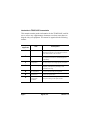
Introduction to TE405P/410P Documentation
This manual contains product information for the TE405P/410P card. Be
sure to refer to any supplementary documents or release notes that were
shipped with your equipment. The manual is organized in the following
manner:
Chapter/
Appendix
Title
Description
1
Overview
Identifies the type of card you received (TE405P or
TE410P). This chapter covers applications and uses
of the TE405P/410P in the real world.
2
Card Installation
Provides instructions for installing the card in your
PC, acquiring correct drivers, and checking device
compatibility.
3
Configuration
Provides examples for configuring dial plan options.
4
Troubleshooting
Explains resolutions to common problems and
frequently asked questions pertaining to card
installation and usage.
A
Pin Assignments
Lists the connectors and pin assignments.
B
Specifications
Details card specifications.
C
Asterisk
Configuration
Commands
Describes all available configuration commands and
their option settings in the zapata.conf file.
Page 6
Digium, Inc.
Release 1.0
D
Dial Plan
Applications
Defines configuration features in the extensions.conf
file.
E
Glossary and
Acronyms
Defines terms related to this product.
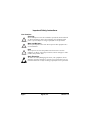
Symbol Definitions
Caution statements indicate a condition where damage to the unit or
its configuration could occur if operational procedures are not
followed. To reduce the risk of damage or injury, follow all steps or
procedures as instructed.
The ESD symbol indicates electrostatic sensitive devices. Observe
precautions for handling devices. Wear a properly grounded
electrostatic discharge (ESD) wrist strap while handling the device.
The Electrical Hazard Symbol indicates a possibility of electrical
shock when operating this unit in certain situations. To reduce the
risk of damage or injury, follow all steps or procedures as
instructed.
Release 1.0
Digium, Inc.
Page 7
Important Safety Instructions
User Cautions
Servicing.
Do not attempt to service this card unless specifically instructed to do
so. Do not attempt to remove the card from your equipment while
power is present. Refer servicing to qualified service personnel.
Water and Moisture.
Do not spill liquids on this unit. Do not operate this equipment in a
wet environment.
Heat.
Do not operate or store this product near heat sources such as
radiators, air ducts, areas subject to direct, intense sunlight, or other
products that produce heat.
Static Electricity.
To reduce the risk of damaging the unit or your equipment, do not
attempt to open the enclosure or gain access to areas where you are
not instructed to do so. Refer servicing to qualified service personnel.
Page 8
Digium, Inc.
Release 1.0
TABLE OF CONTENTS
Chapter 1
Overview . . . . . . . . . . . . . . . . . . . . . . . . . . . . . . . . . . . . . . . . . . . . . . .13
What is Asterisk? . . . . . . . . . . . . . . . . . . . . . . . . . . . . . . . . . . . . . . .18
Chapter 2
Card Installation . . . . . . . . . . . . . . . . . . . . . . . . . . . . . . . . . . . . . . . . .19
Unpacking the Card . . . . . . . . . . . . . . . . . . . . . . . . . . . . . . . . . . . . .19
Shipment Inspection . . . . . . . . . . . . . . . . . . . . . . . . . . . . . . . . . . . .20
Identifying Communication Ports . . . . . . . . . . . . . . . . . . . . . . . . . .20
T1/E1 Selection . . . . . . . . . . . . . . . . . . . . . . . . . . . . . . . . . . . . . . .23
Identifying Multiple Cards . . . . . . . . . . . . . . . . . . . . . . . . . . . . . . . .23
Connecting Timing Cables . . . . . . . . . . . . . . . . . . . . . . . . . . . . . . .24
PCI Slot Compatibility . . . . . . . . . . . . . . . . . . . . . . . . . . . . . . . . . . .25
Hardware Installation . . . . . . . . . . . . . . . . . . . . . . . . . . . . . . . . . . .27
Software Installation . . . . . . . . . . . . . . . . . . . . . . . . . . . . . . . . . . . .28
Chapter 3
Configuration . . . . . . . . . . . . . . . . . . . . . . . . . . . . . . . . . . . . . . . . . . . .33
Configuring T1/E1 Lines . . . . . . . . . . . . . . . . . . . . . . . . . . . . . . . . .33
Testing Your configuration. . . . . . . . . . . . . . . . . . . . . . . . . . . . . . . .40
Chapter 4
Troubleshooting . . . . . . . . . . . . . . . . . . . . . . . . . . . . . . . . . . . . . . . . .43
Appendix A
Release 1.0
Digium, Inc.
Page 9
Table Of Contents
Pin Assignments . . . . . . . . . . . . . . . . . . . . . . . . . . . . . . . . . . . . . . . . .49
Appendix B
Specifications . . . . . . . . . . . . . . . . . . . . . . . . . . . . . . . . . . . . . . . . . . .51
Appendix C
Asterisk Configuration Commands . . . . . . . . . . . . . . . . . . . . . . . . . .53
Appendix D
Dial Plan Applications . . . . . . . . . . . . . . . . . . . . . . . . . . . . . . . . . . . .61
Appendix E
Glossary and Acronyms . . . . . . . . . . . . . . . . . . . . . . . . . . . . . . . . . . .65
Figure 1:
Figure 2:
Figure 3:
Figure 4:
Figure 5:
Figure 6:
Figure 7:
Figure 8:
Figure 9:
Figure 10:
Figure 11:
Figure 12:
Page 10
List of Figures
Sample Legacy Phone Application . . . . . . . . . . . . . .15
Sample Channel Bank Application . . . . . . . . . . . . . .16
Sample IP Phone Application . . . . . . . . . . . . . . . . . .17
TE405P Card . . . . . . . . . . . . . . . . . . . . . . . . . . . . . .21
TE410P Card . . . . . . . . . . . . . . . . . . . . . . . . . . . . . .22
T1/E1 Jumpers . . . . . . . . . . . . . . . . . . . . . . . . . . . . .23
Ident Wheel . . . . . . . . . . . . . . . . . . . . . . . . . . . . . . . .24
Timing Ports . . . . . . . . . . . . . . . . . . . . . . . . . . . . . . .25
Motherboard PCI Slots . . . . . . . . . . . . . . . . . . . . . . .26
Insert the Card . . . . . . . . . . . . . . . . . . . . . . . . . . . . .27
List PCI Slots Screen Capture . . . . . . . . . . . . . . . . .29
dmesg Screen Capture . . . . . . . . . . . . . . . . . . . . . . .40
Digium, Inc.
Release 1.0
Table Of Contents
Table A-1:
Table B-2:
Release 1.0
List of Tables
RJ45 Telco Port Connector . . . . . . . . . . . . . . . . . . . .49
Maximum Power Consumption . . . . . . . . . . . . . . . . .52
Digium, Inc.
Page 11
Table Of Contents
Page 12
Digium, Inc.
Release 1.0
Chapter 1
Overview
The Digium TE405P/410P is a T1/E1 capable card for voice and data. It
supports industry standard protocols, including Robbed Bit Signaling,
E&M, Primary Rate ISDN (PRI), and several data modes (PPP, HDLC,
Cisco HDLC and frame relay). It is capable of running in E1, T1, or J1
modes. It is also capable of DACSing channels from one span to another.
The TE405P/410P is ideal for connecting phones to a channel bank,
connecting to your T1/E1 switch, or connecting to a legacy PBX.
Note: This manual is for use with the 5 volt TE405P and the 3.3 volt
TE410P Quad T1/E1 PCI cards, and are identified collectively as the
TE405P/410P card throughout this manual.
Designed to be fully compatible with existing software applications and
integrate fully with Asterisk Open Source PBX/IVR platform, the
TE405P/410P card allows many advanced call features.
Data Modes:
Cisco HDLC
HDLC
PPP
Multilink PPP
Frame Relay
Release 1.0
Digium, Inc.
Page 13
Chapter 1: Overview
Voice Modes:
PRI CPE and PRI NET
– NI1
– NI2
– EuroISDN
– 4ESS (AT&T)
– 5ESS (Lucent)
– DMS100
E&M
– Wink
– Feature Group B
– Feature Group D
FXO and FXS
– Ground Start
– Loop Start
– Loop Start with Disconnect Detect
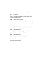
The TE405P/410P card can be used to connect your Asterisk machine to
the PSTN world, your channel bank, or even another PBX. This is
accomplished via a T1/E1 interface. The card allows Asterisk PBX
software to connect to your network, creating a professional telephony
environment. Figure 2 shows an example of the card’s primary
application.
Page 14
Digium, Inc.
Release 1.0
7(3RU
7(3
Chapter 1: Overview
Figure 1: Sample Legacy Phone Application
Release 1.0
Digium, Inc.
Page 15
7(3RU
7(3
Chapter 1: Overview
Figure 2: Sample Channel Bank Application
Page 16
Digium, Inc.
Release 1.0
7(3RU
7(3
Chapter 1: Overview
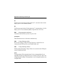
Figure 3: Sample IP Phone Application
Release 1.0
Digium, Inc.
Page 17
Chapter 1: Overview
What is Asterisk?
Asterisk is the first Open Source PBX. Since it runs on Linux, it inherits
all of the power and stability of the operating system. The name Asterisk
is derived from the all-inclusive “wildcard” symbol in UNIX, because it
is opening a wide range of opportunities for developers worldwide to
create solutions which would otherwise be cost-prohibitive.
Asterisk allows you to create a PBX solution that rivals the features and
functionality of traditional telephony switches. Current PBX solutions are
expensive and proprietary. International companies are discovering that
Asterisk is cost effective, low maintenance, and flexible enough to handle
all of their voice and data networking. Combined with Digium hardware
and a common PC, anyone can replace an existing switch or complement
a PBX by adding VoIP, voicemail, conferencing, and many other
capabilities. Asterisk will integrate with most standards-based IP
telephone handsets and software. Analog phones and ADSI-screen
phones are also supported.
Page 18
Digium, Inc.
Release 1.0
Chapter 2
Card Installation
This chapter provides the following information:
Unpacking the Card on page 19
Shipment Inspection on page 20
Identifying Communication Ports on page 20
T1/E1 Selection on page 23
Identifying Multiple Cards on page 23
Connecting Timing Cables on page 24
PCI Slot Compatibility on page 25
Hardware Installation on page 27
Software Installation on page 28
Unpacking the Card
When you unpack your card, carefully inspect it for any damage that may
have occurred in shipment. If damage is suspected, file a claim with the
carrier and contact your reseller where the card was purchased, or Digium
Technical Support (+1.256.428.6161). Keep the original shipping
container to use for future shipment or proof of damage during shipment.
Note: Only qualified service personnel should install the card. Users
should not attempt to perform this function themselves.
Release 1.0
Digium, Inc.
Page 19
Chapter 2: Card Installation
Shipment Inspection
The following items are included in shipment of the TE405P/410P:
TE405P or TE410P card.
User’s manual.
Asterisk Standard Edition Linux Installation CD.
T1 crossover cable, T1 cable, and loopback connector.
TM
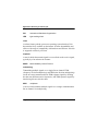
Identifying Communication Ports
The TE405P/410P card consists of four RJ45 ports and four status LEDs.
The ports are used for connecting T1, E1, or J1 cables. See Figure 4 on
page 21 and Figure 5 on page 22 to locate the ports and LEDs.
Page 20
Digium, Inc.
Release 1.0
Chapter 2: Card Installation
Timing
Port
Ports
1
Status
LEDs
2
Jumpers
Ident
Wheel
3
4
Keyed for
5 volt PCI
Figure 4: TE405P Card
Release 1.0
Digium, Inc.
Page 21
Chapter 2: Card Installation
Timing
Port
Ports
1
Status
LEDs
2
Jumpers
3
Ident
Wheel
4
Keyed for
3.3 volt PCI
Figure 5: TE410P Card
Page 22
Digium, Inc.
Release 1.0
Chapter 2: Card Installation
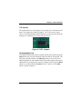
T1/E1 Selection
The card includes a row of jumpers to select either T1 or E1 mode for the
spans. The jumpers are shown in Figure 6. The T1/E1 mode, in most
cases, is set at the distributor before shipment. You may want to check the
setting to be certain they are set for your specific use.
Figure 6: T1/E1 Jumpers
Identifying Multiple Cards
If multiple TE405P/410P cards are installed in the same machine, then the
Ident wheel can be used to control the order the cards are recognized. The
click wheel switch with the word Ident printed above it can be set to a
different number for each installed card. This number adjusts the order in
which the driver recognizes the card. For example: set the first card Ident
wheel to 0, set the second card Ident wheel to 1, and so on. The Ident
wheel is shown in Figure 6.
Release 1.0
Digium, Inc.
Page 23
Chapter 2: Card Installation
Figure 7: Ident Wheel
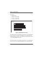
Connecting Timing Cables
The timing port allows up to four TE405P/410P cards to share the same
sync (timing) source from the T1 line provider, or provide a consistent
sync source across multiple cards. This is a useful feature for data and fax
modes and some voice applications to prevent corruption due to timing
slips on the second, third or fourth TE405P/410P PC cards.
To utilize this feature, daisy-chain the P1 connector between each
TE405P/410P card using the Digium 4-position timing cable. See Figure
8 on page 25 for an example. Enable this feature in the drivers using the
timingcable=1 switch when the drivers are loaded:
# modprobe wct4xxp timingcable=1
Page 24
Digium, Inc.
Release 1.0
Chapter 2: Card Installation
Figure 8: Timing Ports
Caution.
Only qualified service personnel should continue with
hardware installation and configuration of the TE405P/410P
card. Users should not attempt to perform these functions
themselves.
PCI Slot Compatibility
Check the type of card you received to be sure it is compatible with your
PCI slot. To determine which slot you have, identify it by comparing it to
those shown in Figure 9 on page 26.
Release 1.0
Digium, Inc.
Page 25
Chapter 2: Card Installation
Slot Number:
0: AGP Pro Slot
1: 64-bit 5.0 volt PCI Slot
2: 64-bit 3.3 volt PCI Slot
3: 32-bit 5.0 volt PCI Slot
Slots
0
1
2
3
Figure 9: Motherboard PCI Slots
The TE405P card is a 32-bit 33MHz card keyed for 5.0 volt operation and
works in any PCI 2.2 (or higher) compliant slot. This means that in the
motherboard shown in Figure 9, the TE405P card will fit into Slots 1 and
3. The TE405P will not fit into Slot 2.
The TE410P card is a 32-bit 33MHz card keyed for 3.3 volt operation and
works in any PCI 2.2 (or higher) compliant slot. This means that in the
Page 26
Digium, Inc.
Release 1.0
Chapter 2: Card Installation
motherboard shown in Figure 9, the TE410P card will only fit into Slot 2.
The TE410P will not fit into Slots 1 or 3.
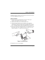
Hardware Installation
1. Now that you are acquainted with the card, power down your
computer and unplug it from its power source.
2. Attach a static strap to your wrist and open the case.
3. Check the jumper setting to ensure it matches your equipment
configuration. Setting the jumper with the strap on enables the ports
for E1. Setting the jumper with the strap off enables the ports for T1.
4. Remove the bracket place holder and insert the card into the PCI slot.
Be certain to place only a TE405P card into a 5 volt PCI slot or the
TE410P card into a 3.3 volt PCI slot. See Figure 10.
Figure 10: Insert the Card
5. Replace the cover to your computer.
Release 1.0
Digium, Inc.
Page 27
Chapter 2: Card Installation
6. Plug all T1 or E1 equipment cables into the RJ45 ports as needed.
Caution.
This unit must be connected to the Telecommunications
Network in your country using an approved line cord, e.g.: for
Australia use only line cords complying with ACA Technical
Standard TS008.
Caution.
This unit must be connected only to the appropriate
Telecommunications Network port (as approved for use in your
specific country).
Software Installation
The card is only supported under Linux. Digium, Inc. recommends
Asterisk Standard Edition, Debian, Fedora, and Red Hat, however, all
other distributions are supported by Digium Technical Support. Digium
hardware requires drivers and libraries that have not yet been integrated
with the Linux kernel. You can obtain the source code from
ftp.digium.com or svn.digium.com.
To install software for your TE405P/410P card, you will need:
Full Linux kernel 2.4 (or later) source code
Development libraries and headers for zlib, libedit, and openssl.
Page 28
Digium, Inc.
Release 1.0
Chapter 2: Card Installation
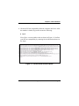
1. Check the PCI bus compatibility. Boot the computer into Linux. After
the machine is loaded, log in and execute the following:
# lspci
You will see a screen similar to the one shown in Figure 11. Confirm
your PCI bus compatibility by scanning for the information shown in
the figure.
Figure 11: List PCI Slots Screen Capture
Release 1.0
Digium, Inc.
Page 29
Chapter 2: Card Installation
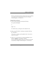
2. Check out the latest driver code and Asterisk software from
ftp.digium.com or svn.digium.com. The following example is
provided to check out the code from the SVN repository:
# cd /usr/src
# svn
trunk
# svn
trunk
# svn
trunk
checkout http://svn.digium.com/svn/asterisk/
asterisk
checkout http://svn.digium.com/svn/zaptel/
zaptel
checkout http://svn.digium.com/svn/libpri/
libpri
Commands to get the current snapshot from the release branch of
SVN:
# svn checkout http://svn.digium.com/svn/asterisk/
branches/1.2 asterisk-1.2
# svn checkout http://svn.digium.com/svn/zaptel/
branches/1.2 zaptel-1.2
# svn checkout http://svn.digium.com/svn/libpri/
branches/1.2 libpri-1.2
This creates the following directories: zaptel, libpri, and Asterisk.
Complete instructions for installing Asterisk is available at
www.asterisk.org.
Page 30
Digium, Inc.
Release 1.0
Chapter 2: Card Installation
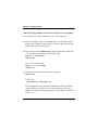
3. Install the zaptel drivers. Compiling the directories is straight forward.
Change to each directory and type make install. Compile in this
order: zaptel, libpri, and Asterisk.
Type the following:
# cd /usr/src/zaptel
# make clean
# make install
Note: If the build fails, it may be because you are missing one of
the build dependencies, the kernel source, or development tools.
Feel free to contact your reseller where the card was purchased, or
call Digium Technical Support (+1.256.428.6161) for assistance.
4. Install libpri and Asterisk.
#cd /usr/src/libpri
#make install
#cd /usr/src/asterisk
#make
#make install
#make samples
Note: This step installs sample configuration files which are
necessary for Asterisk. You will make changes to these
configuration files to set up your dial plan and customize Asterisk
to suit your particular needs.
Release 1.0
Digium, Inc.
Page 31
Chapter 2: Card Installation
Page 32
Digium, Inc.
Release 1.0
Chapter 3
Configuration
The TE405P/410P cards have a variety of configuration options. This
chapter provides configurations for PRI, channel bank, E&M wink, and
finally, data mode. These sample configurations are provided to assist you
in familiarizing yourself with the flexibility of editing the configuration
files to meet your specific needs. The list of possible configurations is too
expansive to cover in this user manual.
Configuring T1/E1 Lines
1. Begin by opening the zaptel.conf file from the /etc/asterisk/
directory.
2. Configure the SPAN Map.
For each T1/E1 you are using you will need to define a span. The
SPAN map includes defining the SPAN number, timing, line build out,
framing and coding. Configuration details for each of these items is
explained in this section.
span => NUMBER,TIMING,LINE BUILD OUT,FRAMING,CODING
Number:
This is the port the span is plugged into. Port 1 being the furthest span
from the PCI bus. The port numbers are notated on the PCI bracket.
Release 1.0
Digium, Inc.
Page 33
Chapter 3: Configuration
Timing:
Determines whether the card provides timing (0), takes timing (1),
takes backup span timing (2), provides backup span timing (3), and so
on. Only one span can be defined to take timing and it defines timing
for the rest of the card spans.
Line Build Out
For most setups the line build out is 0.
0: 0 db (CSU) / 0-133 feet (DSX-1)
1: 133-266 feet (DSX-1)
2: 266-399 feet (DSX-1)
3: 399-533 feet (DSX-1)
4: 533-655 feet (DSX-1)
5: -7.5db (CSU)
6: -15db (CSU)
7: -22.5db (CSU)
Framing
T1 utilizes framing set for D4 (SF) or ESF. E1 utilizes CAS or CCS.
Coding
T1 coding can be AMI or B8ZS. E1 coding can be AMI or HDB3. E1
can also have the extra flag CRC4 at the end for CRC4 checking.
Yellow flag can also be added at the end for transmitting a yellow
alarm when all channels are in use.
Page 34
Digium, Inc.
Release 1.0
Chapter 3: Configuration
The following is a typical setup for a telco in the US:
span => 1,1,0,esf,b8zs
In Europe:
span=>1,1,0,ccs,hdb3
First Example: Channel Bank
The Channel Bank in this example has 24 FXS ports. In this
configuration, the zaptel.conf is set for the card to provide timing to the
channel bank and fxoks is set for 24 stations.
Set zapata.conf to mirror the configuration with signalling=fxo_ks
and define it for channels 1-24.
/etc/zaptel.conf:
span=1,0,0,esf,b8zs
fxoks=1-24
/etc/asterisk/zapata.conf:
group=1
context=channelbank
signalling=fxo_ks
channel=1-24
Second Example: E&M Line
In the E&M Line configuration, the zaptel.conf is set for the card to take
timing from the telco on E&M with wink while zapata.conf mirrors the
Release 1.0
Digium, Inc.
Page 35
Chapter 3: Configuration
configuration. However, Feat_D is a type of E&M with wink that accepts
DID, but there are many E&M options; E&M_W, E&M, Feat_B, etc.
/etc/zaptel.conf:
span=1,1,o,esf,b8zs
e&m=1-24
/etc/asterisk/zapata.conf:
group=1
context=incoming
signalling=feat_d
channel=1-24
Third Example: PRI
By setting the card to take timing in zaptel.conf, you acquire 23 b
channels and voice channels, with channel 24 as the data transport. For
Asterisk, define PRI_CPE so it is the client side. Define the switch type
you are connecting to as national. There are several options for the switch
type including 5ESS, 4ESS, and NI1. You will then have 23 voice
channels for Asterisk.
Page 36
Digium, Inc.
Release 1.0
Chapter 3: Configuration
PRI T1
/etc/zaptel.conf:
span=1,1,0,esf,b8zs
bchan=1-23
dchan=24
/etc/asterisk/zapata.conf
group=1
signalling=pri_cpe
switchtype=national
context=incoming
channel=1-23
PRI E1
/etc/zaptel.conf:
span=1,1,0,ccs,hdb
bchan=1-15,17-31
dchan=16
/etc/asterisk/zapata.conf
group=1
signalling=pri_cpe
switchtype=euroisdn
context=incoming
channel=1-15,17-31
Release 1.0
Digium, Inc.
Page 37
Chapter 3: Configuration
Fourth Example: Data Mode
Data mode is a little different than the other options. The zaptel.conf is
configured as follows:
/etc/zaptel.conf
span=1,0,0,esf,b8zs
nethdlc=1-24
1. Instructions for Cisco HDLC:
Compile kernel with HDLC support:
Note: We suggest that you use either a Kernel version of 2.4.20 or
less, or a Kernel of 2.6.8 or greater. The HDLC implementation in the
interval kernels is in a state of too much flux. The following data
modes are described in this section:
– WAN Interfaces Support
– Generic HDLC Layer
– Cisco HDLC support
2. Rebuild and reboot into your kernel.
3. Uncomment the following line in zconfig.h of the Zaptel package:
#define CONFIG_ZAPATA_NET
If you are using a kernel prior to 2.4.19, also uncomment this line:
#define CONFIG_OLD_HDLC_API
Page 38
Digium, Inc.
Release 1.0
Chapter 3: Configuration
Rebuild Zaptel including the creation of the SetHDLC utility:
make sethdlc-new;use "make sethdlc" for
;kernels 2.4.19 and prior
make install
4. Load and configure your driver:
modprobe wct4xxp
ztcfg
5. Use sethdlc to bring up the interface:
sethdlc hdlc0 cisco
-or- for old style (make sethdlc instead of sethdlc-new) use:
sethdlc hdlc0 mode cisco
6. Assign the interface an address:
ifconfig hdlc0 192.168.0.1 netmask 255.255.255.0
7. The interface may be addressed as any other networking interface
(i.e., eth0) in Linux.
Release 1.0
Digium, Inc.
Page 39
Chapter 3: Configuration
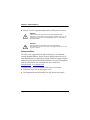
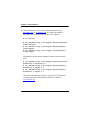
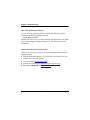
Testing Your configuration.
1. Load Zaptel drivers into the kernel using the program modprobe. The
appropriate driver for the TE405P/410P card is wct4xxp. Users in all
countries except Australia should use the following modprobe
command:
# modprobe wct4xxp
ztcfg -vv
dmesg screen import
Figure 12: dmesg Screen Capture
Page 40
Digium, Inc.
Release 1.0
Chapter 3: Configuration
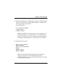
2. Run zttool from the command line and see if the span turns green for
each span you have connected.
zttool
3. Execute the following Asterisk command to see if the span came up
successfully.
asterisk
asterisk -vvvr
Note: More detailed information is provided on troubleshooting in the
Asterisk User’s Manual. A copy may be requested by contacting
Digium Technical Support (+1.256.428.6161) or visiting the website
at www.digium.com. You may also contact your distributor or reseller
where the card was purchased for assistance.
Release 1.0
Digium, Inc.
Page 41
Chapter 3: Configuration
Page 42
Digium, Inc.
Release 1.0
Chapter 4
Troubleshooting
This chapter provides frequently asked questions as identified from
Digium Technical Support and possible resolutions. Multiple resources
are available to obtain more information about Asterisk and Digium
products. These resources are listed on page 47.
What do the LED colors indicate?
Green - Card is in-sync with the far end.
Yellow - Card is synchronizing.
Red - Card is not seeing far end, circuit is not up, or cable is bad.
I can't receive DID calls even though I have it enabled in
extensions.conf.
Your telco might be sending calls with a method you are not expecting.
1. Check the method being used by attempting the following in your line
context:
_x.,1,noop(My DID Matches as ${EXTEN}
2. Then type reload in the Asterisk console and call in. You should see
the DID come in on your T1/E1 line.
Release 1.0
Digium, Inc.
Page 43
Chapter 4: Troubleshooting
My D Channel seems to go up and down.
Check to be sure you have set your timing parameters correctly. Also
check the common causes of problems for a T1. See the Common Fixes
for all cards, page 46.
I have trouble dialing out. It seems that one type of dialing works
(local, long distance, international) but another does not.
Check your pridialplan variable and be sure that you are dialing using the
method your telco is expecting.
I am having trouble receiving DID information over E&M.
Try the other types of E&M (featd, featb, etc.) to match the method your
telco is using to stream information.
I am having issues with my PRI. How can I see the messages coming
across my D channel?
Enter the following command:
PRI debug span X
where x is the port from which you are connected. This command will
show you the PRI messages coming across your D channel for that
message.
Page 44
Digium, Inc.
Release 1.0
Chapter 4: Troubleshooting
I am still having problems and the telco tells me it is my equipment.
The first thing to do in this situation is to test your equipment.
1. Plug in a loopback cable. (A loopback cable is a cable that has pin 1
going to pin 4 and pin 2 going to pin 5.) Plug the cable into the span
and wait for its LED to turn green.
2. Stop Asterisk and edit zaptel.conf by removing the lines defined for
your card and replacing them with the following:
span=>1,0,0,esf,b8zs
clear=1-24
Or if you have an E1 span:
span=> 1,0,0,ccs,hdb3
clear=1-31
3. Navigate to your zaptel source directory and type:
make tests
Followed by:
./patlooptest /dev/zap/1 60
The first argument in the patlooptest command is the device for the
channel number you want to test. You should always test the first
channel of a span. The second argument is the duration in seconds to
run the test.
Release 1.0
Digium, Inc.
Page 45
Chapter 4: Troubleshooting
This runs a pattern looptest for 60 seconds. If you receive any failures,
it is possible you have a bad card and will need to call Digium
Technical Support (+1.256.428.6161)
Common Fixes for all cards
1. Check for shared interrupts by entering the following:
cat /proc/interrupts
or
lspci -vb
If a conflict exists, try moving the card to another PCI slot.
2. Check to see if X windows is running by entering the following:
ps aux|grep X
If X windows is running, stop the application since it may cause a
conflict with Asterisk.
3. Check to see if your hard drives are running with DMA levels set.
Perform an hdparm on your hard drive interface.
If you are still having problems contact your reseller where the card
was purchased, or Digium Technical Support (+1.256.428.6161).
Page 46
Digium, Inc.
Release 1.0
Chapter 4: Troubleshooting
How can I enable more features?
To view all of the options available to add to your dial plan, type the
following command from within Asterisk:
show applications
Digium also offers services to help configure and add features you might
need. Contact Digium Technical Support (+1.256.428.6161) for more
information.
Where can I ask even more questions?
There are several places to inquire for more information about Asterisk
Digium products:
1. Digium Technical Support (+1.256.428.6161) is available 7am-7pm
Central Time, Monday - Friday.
2. Asterisk forums (forums.digium.com).
3. Asterisk users mailing list (asterisk.org/lists.digium.com).
4. IRC channel #asterisk on (irc.freenode.net).
Release 1.0
Digium, Inc.
Page 47
Chapter 4: Troubleshooting
Page 48
Digium, Inc.
Release 1.0
Appendix A
Pin Assignments
All four ports on the TE405P/410P bracket are 8-pin RJ45 ports. The pin
assignments are identified in Table A-1.
Table A-1: RJ45 Telco Port Connector
Pin 1
Pin 8
Release 1.0
Pin
Description
1
Rx
2
Rx
3
Not used
4
Tx
5
Tx
6
Not used
7
Not used
8
Not used
Digium, Inc.
Page 49
Appendix A: Pin Assignments
Page 50
Digium, Inc.
Release 1.0
Appendix B
Specifications
This appendix provides specifications, required environmental
conditions, and maximum power consumption for the TE405P/
410P card.
Physical.
Size:
Weight:
5” × 3.75” × 0.63” (12.7 x 9.53 x 1.6 cm)
PCB size, does not include the PCI bracket
3.5 oz (100gm)
Interfaces.
Local Loop Access: E1, T1, J1, PRI; RJ45
PCI Bus: 3.3V or 5V bus slot, half-length slot minimum size,
33MHz minimum bus speed, compliant with PCI 2.2 or greater.
Environment.
Temperature: 0 to 50° C (32 to 122° F) operation
-20 to 65° C (4 to 149° F) storage
Humidity: 10 to 90% non-condensing
Release 1.0
Digium, Inc.
Page 51
Appendix B: Specifications
Hardware and Software Requirements.
800-Mhz Pentium III or better
64MB RAM
Available PCI Slot (as described previously)
Table B-2: Maximum Power Consumption
Model
Page 52
Power
TE405P
3.3V
5V
2 Watts
0 Watts
TE410P
3.3V
5V
2 Watts
Unused
Digium, Inc.
Release 1.0
Appendix C
Asterisk Configuration Commands
This appendix provides the configuration options available in the
zapata.conf file which is created during the initial installation of
Asterisk. To change any of the following features, edit the
zapata.conf file with your text editor, saving the file upon
completion. The following lists the command, description, and the
available options:
adsi
ADSI (Analog Display Services Interface) can be enabled on a perchannel basis if you have (or may have) ADSI compatible CPE
equipment.
yes / no
busycount
If enabled, it is also possible to specify how many busy tones to wait
before hanging up.
positive integer
busydetect
On trunk interfaces (FXS) and E&M interfaces (E&M, Wink, Feature
Group D, etc.), it can be useful to perform busy detection either in an
effort to detect hangup or for detecting busy signals.
yes / no
Release 1.0
Digium, Inc.
Page 53
Appendix C: Asterisk Configuration Commands
cadence
You can define your own custom ring cadences, up to 8 pairs. If the
silence is negative, it indicates where the callerid spill is to be placed.
Also, if you define any custom cadences, the default cadences will be
turned off.
Syntax is: cadence=ring,silence [,ring,silence[...]]
The default is based on the country code.
callerid
CallerID can be set to asreceived or a specific number if you want to
override it. Note that asreceived only applies to trunk interfaces.
asreceived or a specific number
callgroup, pickupgroup
Supports ring groups (a.k.a. call groups) and pickup groups. If a phone is
ringing and it is a member of a group which is one of your pickup groups,
then you can answer it by picking up and dialing *8#.
For simple offices, set these both to the same positive integer.
callprogress, progzone
On trunk interfaces (FXS), it can be useful to attempt to follow the
progress of a call through ringing, busy, and answering. If enabled, call
progress attempts to determine answer, busy, and ringing on phone lines.
This feature is HIGHLY EXPERIMENTAL and can easily detect false
answers, so DO NOT rely on it being accurate.
Few zones are supported at the time of this writing, but may be selected
with progzone, yes / no, and two letter country code for progzone.
callreturn
Support call return (*69).
yes / no
Page 54
Digium, Inc.
Release 1.0
Appendix C: Asterisk Configuration Commands
callwaiting
Enable call waiting on FXO lines.
yes / no
callwaitingcallerid
Support caller ID on call waiting.
yes / no
canpark
Allow call parking.
yes / no
cidsignalling
Type of caller ID signalling in use.
bell =bell202 (US)
v23 = v23 (UK)
dtmf = DTMF (Denmark, Sweden, & Netherlands)
cidstart
Identifies what signals the start of caller ID.
ring = a ring signals the start
polarity = polarity reversal signals the start
echocancel
Enable echo cancellation.
yes / no, or a power of two from 32 to 256 (if you want to actually set the
number of cancellation taps)
Release 1.0
Digium, Inc.
Page 55
Appendix C: Asterisk Configuration Commands
echocancelwhenbridged
Generally, it is not necessary (and in fact undesirable) to echo cancel
when the circuit path is entirely TDM. You may, however, reverse this
behavior by enabling the echo cancel during pure TDM bridging.
yes / no
echotraining
In some cases, the echo canceller doesn't train quickly enough and there
is echo at the beginning of the call. Enabling echo training will cause
Asterisk to briefly mute the channel, send an impulse, and use the impulse
response to pre-train the echo canceller so it can start out with a much
closer idea of the actual echo.
Value may be yes, no, or a number of milliseconds (positive int) to delay
before training.
(default = 400)
faxdetect
Upon fax detection, routes fax to a fax extension.
Both, incoming, outgoing, or no.
group
Logical groups can be assigned to allow outgoing rollover.
Groups range from 0 to 63, and multiple groups can be specified.
hanguponpolarityswitch
In some countries, a polarity reversal is used to signal the disconnect of a
phone line. If this option is enabled, the call will be considered
disconnected on a polarity reversal.
yes / no
Page 56
Digium, Inc.
Release 1.0
Appendix C: Asterisk Configuration Commands
hidecallerid
Hide outgoing caller ID. Override with *67 or *82.
yes / no
immediate
Specify whether the channel should be answered immediately or if the
simple switch should provide dialtone, read digits, etc.
yes / no
jitterbuffers
Configure jitter buffers in zapata.
(each one is 20ms, default is 4) positive integer
mailbox
Supports stutter dialtone.
If a mailbox is specified without a voicemail context, then when message
is received, taking the phone off hook will cause a stutter dialtone instead
of a normal dialtone. If a mailbox is specified with a voicemail context,
the same will result if a message is received in the specified voicemail
context.
mailbox ex. 1234, or 1234@other.
musiconhold
Select which class of music to use for music on hold. If not specified then
the default will be used. The music class is defined in musiconhold.conf
file.
default, loud, random
pulsedial
Use pulse dial instead of DTMF for FXO (FXS signalled) devices.
yes / no
Release 1.0
Digium, Inc.
Page 57
Appendix C: Asterisk Configuration Commands
relaxdtmf
If you have trouble with DTMF detection, you can relax the DTMF
detection parameters. Relaxing them may make the DTMF detector more
likely to have talk off where DTMF is detected incorrectly.
yes / no
rxgain
Receive gain.
Positive or negative double, measured in dB. Digium recommends a
range of -5 to 5.
sendcalleridafter
Some countries have ring tones with a set of cadences which differ from
the default (e.g. UK uses ring-ring). This requires the callerid to be set
with a delay, and not right after the first ring (the default).
Positive integer
threewaycalling
Support three-way calling.
yes / no
transfer
Support flash-hook call transfer (requires three way calling). Also
enables call parking (overrides the canpark parameter).
yes / no
txgain
Transmit gain.
Positive or negative double, measured in dB. Digium recommends a
range of -5 to 5.
Page 58
Digium, Inc.
Release 1.0
Appendix C: Asterisk Configuration Commands
usecallerid
Whether or not to use caller ID.
yes / no
usedistinctiveringdetection
Indicates whether or not to allow distinctive ring detection on FXO lines.
yes / no
Release 1.0
Digium, Inc.
Page 59
Appendix C: Asterisk Configuration Commands
Page 60
Digium, Inc.
Release 1.0
Appendix D
Dial Plan Applications
This appendix details the applications available for configuring the
dial plan. The dial plan is customized in the extensions.conf file
which is created during the initial installation of Asterisk. This file
controls how all calls are handled and routed. To change any of the
following options, edit the extensions.conf file, saving the file upon
completion. The following defines each feature:
AgentCallbackLogin
Call agent callback login
AgentLogin
Call agent login
AGI
Executes an AGI compliant application
Answer
Answer a channel if ringing
Authenticate
Authenticate a user
BackGround
Play a file while awaiting extension
Release 1.0
Digium, Inc.
Page 61
Appendix D: Dial Plan Applications
BackgroundDetect
Background a file with talk detect
Busy
Indicate busy condition and stop
Dial
Place a call and connect to the current channel
Directory
Provide directory of voicemail extensions
DISA
DISA (Direct Inward System Access)
Goto
Go to a particular priority, extension, or context
GotoIf
Conditional goto
GotoIfTime
Conditional goto on current time
Hangup
Unconditional hangup
Macro
Macro Implementation
Monitor
Monitor a channel
Page 62
Digium, Inc.
Release 1.0
Appendix D: Dial Plan Applications
MusicOnHold
Play music on hold indefinitely
Playback
Play a file
Queue
Queue a call for a call queue
Record
Record to a file
SetCallerID
Set CallerID
SetCallerPres
Set CallerID presentation
SetCIDName
Set CallerID name
SetCIDNum
Set CallerID number
VoiceMail
Leave a voicemail message
VoiceMailMain
Enter voicemail system
Zapateller
Block telemarketers with SIT
Release 1.0
Digium, Inc.
Page 63
Appendix D: Dial Plan Applications
Page 64
Digium, Inc.
Release 1.0
Appendix E
Glossary and Acronyms
ANSI
American National Standards Institute
An organization which proposes and establishes standards for
international communications.
asynchronous
Not synchronized; not timed to an outside clock source. Transmission is
controlled by start bits at the beginning and stop bits at the end of each
character. Asynchronous communications are often found in internet
access and remote office applications.
attenuation
The dissipation of a transmitted signal’s power as it travels over a wire.
bandwidth
The capacity to carry traffic. Higher bandwidth indicates the ability to
transfer more data in a given time period.
bit
The smallest element of information in a digital system. A bit can be
either a zero or a one.
bps
bits per second
A measurement of transmission speed across a data connection.
Release 1.0
Digium, Inc.
Page 65
Appendix E: Glossary and Acronyms
broadband
Broadband transmission shares the bandwidth of a particular medium
(copper or fiber optic) to integrate multiple signals. The channels take up
different frequencies on the cable, integrating voice, data, and video over
one line.
channel
A generic term for an individual data stream. Service providers can use
multiplexing techniques to transmit multiple channels over a common
medium.
Cat5
Category of Performance for wiring and cabling. Cat 5 cabling support
applications up to 100 MHz.
Cat5E
Category of Performance for wiring and cabling. Category 5 Enhanced
wiring supports signal rates up to 100 MHz but adheres to stricter quality
specifications.
CLEC
competitive local exchange carrier
A term for telephone companies established after the
Telecommunications Act of 1996 deregulated the LECs. CLECs compete
with ILECs to offer local service. See also LEC and ILEC.
Page 66
Digium, Inc.
Release 1.0
Appendix E: Glossary and Acronyms
CO
central office
The CO houses local switching equipment. All local access lines in a
particular geographic area terminate at this facility (which is usually
owned and operated by an ILEC).
CPE
customer premises equipment
Terminal equipment which is connected to the telecommunications
network and which resides within the home or office of the customer. This
includes telephones, modems, terminals, routers, and television set-top
boxes.
DS0
Digital Signal, Level 0
A voice grade channel of 64 Kbps. The worldwide standard speed for
digitizing voice conversation using PCM (Pulse Code Modulation).
DS1
Digital Signal, Level 1
1.544 Mbps in North America (T1) and Japan (J1) -up to 24 voice
channels (DS0s), 2.048 Mbps in Europe (E1) - up to 32 voice channels
(DS0s). DS1/T1/E1 lines are part of the PSTN.
DS3
Digital Signal, Level 3
T3 in North America and Japan, E3 in Europe. Up to 672 voice channels
(DS0s). DS3/T3/E3 lines are not part of the PSTN
DTMF
Dual Tone Multi-Frequency
Push-button or touch tone dialing.
Release 1.0
Digium, Inc.
Page 67
Appendix E: Glossary and Acronyms
E1
The European equivalent of North American T1, transmits data at 2.048
Mbps, up to 32 voice channels (DS0s).
E3
The European equivalent of North American T3, transmits data at 34.368
Mbps, up to 512 voice channels (DS0s). Equivalent to 16 E1 lines.
EMI
Electromagnetic Interference
Unwanted electrical noise present on a power line
full duplex
Data transmission in two directions simultaneously.
FXO
Foreign Exchange Office
Receives the ringing voltage from an FXS device. Outside lines are
connected to the FXO port on your TE405P/410P card.
FXS
Foreign Exchange Station
Initiates and sends ringing voltage. Phones are connected to the FXS ports
on the TE405P/410P card.
G.711
The International Telecommunications Union recommendation for an
algorithm designed to transmit and receive mulaw PCM voice and A-law
at digital bit rate 64 Kbps. This algorithm is used for digital telephone sets
on digital PBX.
Page 68
Digium, Inc.
Release 1.0
Appendix E: Glossary and Acronyms
G.729
An International Telecommunications Union standard for voice
algorithm.
H.323
An International Telecommunications Union standard for multimedia
communications over packet-based networks.
IAX
Inter-Asterisk eXchange
A VoIP protocol used by Asterisk. It is used to enable VoIP connections
between Asterisk servers, and between servers and clients that also use
the IAX protocol.
iLBC
internet Low Bitrate Codec
A free speech codec used for voice over IP. It is designed for narrow band
speech with a payload bitrate of 13.33 kbps (frame length = 30ms) and
15.2 kbps (frame length = 20 ms).
ILEC
incumbent local exchange carrier
The LECs that were the original carriers in the market prior to the entry of
competition and therefore have the dominant position in the market.
interface
A point of contact between two systems, networks, or devices.
Release 1.0
Digium, Inc.
Page 69
Appendix E: Glossary and Acronyms
ISO
International Standards Organization
LED
light-emitting diode
Linux
A robust, feature-packed open source operating system based on Unix
that remains freely available on the internet. It boasts dependability and
offers a wide range of compatibility with hardware and software. Asterisk
is supported exclusively on Linux.
loopback
A state in which the transmit signal is reversed back as the receive signal,
typically by a far end network element.
MGCP
Media Gateway Control Protocol
multiplexing
Transmitting multiple signals over a single line or channel. FDM
(frequency division multiplexing) and TDM (time division multiplexing)
are the two most common methods. FDM separates signals by dividing
the data onto different carrier frequencies, and TDM separates signals by
interleaving bits one after the other.
MUX
multiplexer
A device which transmits multiple signals over a single communications
line or channel. See multiplexing.
Page 70
Digium, Inc.
Release 1.0
Appendix E: Glossary and Acronyms
PBX
private branch exchange
A smaller version of a phone company’s large central switching office.
Example: Asterisk.
PCI
peripheral component interconnect
A standard bus used in most computers to connect peripheral devices.
POP
point of presence
The physical connection point between a network and a telephone
network. A POP is usually a network node serving as the equivalent of a
CO to a network service provider or an interexchange carrier.
POTS
plain old telephone service
Standard phone service over the public switched telephone network
(PSTN). This service provides analog bandwidth of less than 4 kHz.
PPP
point-to-point protocol
Type of communications link that connects a single device to another
single device, such as a remote terminal to a host computer.
PSTN
public switched telephone network
A communications network which uses telephones to establish
connections between two points. Also referred to as the dial network.
QoS
quality of service
A measure of telephone service, as specified by the Public Service
Commission.
Release 1.0
Digium, Inc.
Page 71
Appendix E: Glossary and Acronyms
RJ11
A six-pin jack typically used for connecting telephones, modems, and fax
machines in residential and business settings to PBX or the local
telephone CO.
SIP
Session Initiation Protocol
An IETF standard for setting up sessions between one or more clients. It
is currently the leading signaling protocol for Voice over IP, gradually
replacing H.323.
T1
A dedicated digital carrier facility which transmits up to 24 voice
channels (DS0s) and transmits data at 1.544 Mbps. Commonly used to
carry traffic to and from private business networks and ISPs.
T3
A dedicated digital carrier facility which consists of 28 T1 lines and
transmits data at 44.736 Mbps. Equivalent to 672 voice channels (DS0s).
TDM
time division multiplexer
A device that supports simultaneous transmission of multiple data streams
into a single high-speed data stream. TDM separates signals by
interleaving bits one after the other.
telco
A generic name which refers to the telephone companies throughout the
world, including RBOCs, LECs, and PTTs.
Page 72
Digium, Inc.
Release 1.0
Appendix E: Glossary and Acronyms
tip and ring
The standard termination on the two conductors of a telephone circuit;
named after the physical appearance of the contact areas on the jack plug.
twisted pair
Two copper wires commonly used for telephony and data
communications. The wires are wrapped loosely around each other to
minimize radio frequency interference or interference from other pairs in
the same bundle.
V
volts
VoIP
Voice over IP
Technology used for transmitting voice traffic over a data network using
the Internet Protocol.
Zaptel (Zap)
Zapata Telephony Project dedicated to implementing a reasonable and
affordable Computer Telephony platform into the world marketplace.
Release 1.0
Digium, Inc.
Page 73
Appendix E: Glossary and Acronyms
Page 74
Digium, Inc.
Release 1.0