1
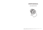
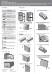
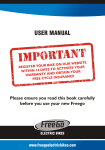
Thitronik providing solutions... C.A.S. Caravan Alarm System Operating instructions Installation manual !! Please read carefully before use !! Manual Revision 1.3 C.A.S. operating instructions Contents Section Page Contents 1 1.1 1 1.2 2 1.3 2 1.4 2 1.5 2 1.6 3 1.7 4 1.8 4 1.9 4 1.9.1 5 1.9.2 5 1.9.3 5 1.9.4 5 1.9.5 6 1.9.6 6 1.9.7 6 1.9.8 6 Handling the system Mode of operation, accessories, disclaimer Controlling the system with the handheld transmitter Alarm storage Activating the panic alarm Running the system without the supply voltage Tamper protection Opening the signal contact (ventilation function) Signal transmitter battery low Changing the signal transmitter battery Changing the transmitter battery, handheld transmitter Changing the transmitter battery, reed switch Changing the transmitter battery, cable loop (accessory) Sequence of a burglary alarm Sequence of a gas alarm (accessory) Interrupting an alarm with the handheld transmitter Using the wireless gas alarm (accessory) Using the cable loop (accessory) 2 2.1 7-8 2.2 9 GSM/GPS Combimodule Using the GSM/GPS Combimodule (accessory) Instructions on using the GSM/GPS Combimodule 3 3.1 11 3.2 11 3.3 11 3.4 11 3.5 11 3.6 12 3.7 12 3.8 12 3.9 13 3.9.1 14 3.9.2 14 3.9.3 14 3.9.4 15 3.9.5 15 3.9.6 16 3.9.7 16 3.9.8 16-17 3.9.9 18 Installing the system Scope of delivery Installation instructions Preparing for installation Opening the system Setting the program selector switch Table 1 Program selector switch Initial start-up Storing contacts or other transmitters Diagrams Disconnecting contacts or other transmitters Installing the wireless contacts Installing the wireless gas alarm (accessory) Installing the cable loop (accessory) Installing the central unit Connecting the central unit Installing the GSM/GPS Combimodule Programming the GSM/GPS Combimodule Performing an alarm test 4 4.1 18-20 4.2 21 4.3 21 4.4 21 4.5 21 Miscellaneous Troubleshooting Approvals Technical specifications Maintenance instructions Disposal instructions C.A.S. operating instructions ! Handling the system Please read the following instructions carefully to avoid faulty operation. Page 1 ! 1.1 Mode of operation, accessories, disclaimer The C.A.S. has been developed especially for caravans. This system does not use motion sensors, which have to be deactivated when the vehicle is staying somewhere and are often the cause of false alarms. The result is a thoroughly user-friendly alarm system which is operated at the touch of a button and is practically immune from false alarms. The interior is secured via wireless magnetic contacts on the doors, windows and hatches. The system is operated via the handheld transmitter supplied or by SMS depending on the configuration. Accessories Accessories which are available include other wireless magnetic contacts, handheld transmitters, wireless cable loops, wireless gas alarms and a GSM/GPS Combimodule for vehicle tracking. By using other wireless magnetic contacts (Item no: THA-2-00008), it is possible to secure baffle plates, windows, doors, roof hatches and even roof boxes. Other handheld transmitters (Item: THA-2-00009) enable other family members etc. to control the system and gain access to the vehicle. By using the wireless cable loop (Item no: THA-2-00012), you can secure movable goods (such as bicycles, motor scooters, surfboards and camping furniture etc.) against theft outside the vehicle. By using one or more wireless gas alarms (Item no: THA-2-00015), you can protect your gas supply from the threat of gas leaks and attacks with narcotic gases. The gas alarm immediately signals the presence of dangerous gases in the room air to the C.A.S. which then gives out an alarm. In the event of an alarm, the GSM/GPS Combimodule (Item no: THA-2-00027) sends an SMS to up to 10 programmable telephone numbers. The alarm system can also be switched on or off via an SMS. By calling the GMS module, status enquiries can be sent at any time requesting information on the status of the C.A.S. and the position, speed and reception quality etc. Disclaimer: As with any other alarm system, C.A.S. can only report a break-in or attempted break-in but cannot prevent it. Therefore, be wise and do not leave any valuables on view or where they are easily accessible in the vehicle and do not leave the vehicle unlocked. Thitronik does not accept any liability for stolen valuables or damage to the vehicle caused by a break-in. C.A.S. operating instructions Page 2 1.2 Controlling the system with the handheld transmitter Any button arms the system. Any button disarms the system. Integrated LEDs flash once and an internal buzzer* sounds once. Integrated LEDs flash twice and an internal buzzer* sounds twice. If the system is disarmed after an alarm event, instead of the buzzer sounding twice it gives out one long continuous sound. *depending on the setting on the program selector switch (Signal tones are not permitted in road traffic) 1.3 Alarm storage After an alarm has stopped, it makes sense to be alerted to the incident from outside the vehicle as you return. After an alarm has stopped, therefore, one of the integrated LEDs flashes at a time alternately. Also, the buzzer give out a long low tone during deactivation. 1.4 Activating the panic alarm If you feel threatened while you are in the vehicle, use the panic alarm function to draw attention. During a panic alarm, the sirens and the LEDs are activated. A panic alarm can be activated whether the system is armed or not armed. The panic alarm is activated by pressing both buttons on the handheld transmitter simultaneously. The panic alarm is deactivated by pressing any button on the handheld transmitter. 1.5 Running the system operated without the 12 V supply voltage If a voltage supply is unavailable from either the vehicle or the parking place, the system will run on an integrated rechargeable battery for up to 48 hours. In order for this to happen, the battery must be charged. The battery is charged when the C.A.S. is supplied with a voltage for at least 9 hours without interruption. C.A.S. operating instructions Page 2 Page 3 1.6 Tamper protection ! C.A.S. has different methods of protection to prevent the system from being tampered with. 1. Stray-field protection on the wireless magnetic contacts and the cable loops When the system is activated and the contact is closed, if another magnet approaches (to bypass the contact) the main alarm is activated immediately. 2. Interference signal detection If the transmitter frequency of the system is superimposed by a radio signal, the LEDs are activated after 5 seconds and the siren sounds after 15 seconds. Once a GSM/GPS module has been connected, an SMS with “interference signal” is transmitted after 5 seconds. 3. Voltage tampering If the supply voltage is interrupted for more than 10 seconds when the system is activated, a pre-alarm (a series of short tones) sounds and after 20 seconds, the main alarm* is activated (siren and LEDs). Once a GSM/GPS module has been connected, an SMS with “tamper voltage” is transmitted after 5 seconds. *depending on the setting on the program selector switch 4. Tampering with the casing cover If the casing cover is opened when the system is activated, the main alarm sounds immediately. Once a GSM/GPS module has been connected, an SMS with “tamper” is transmitted. C.A.S. operating instructions Page 4 1.7 “Open contact” signal (ventilation function) When locking, the interior beeper emits a series of short beeps. This means that the system has detected that one of the wireless magnetic contacts is open. If none of the contacts have been opened intentionally, check all the secured openings. Unlike a passenger vehicle alarm system, in a caravan, you might well want to leave a window open while all the other secured openings are monitored. For example, if you need to ventilate the vehicle. Read the following to see how this can be done. Open the window you have chosen and activate the system as previously described under Point 1.2. When locking, the interior buzzer gives out a series of short beeps. However, the alarm is armed and monitors all the remaining contacts. If the window is closed while the system is activated, the alarm is not triggered. The alarm does not sound until at least 5 seconds has elapsed before a window is opened again. 1.8 “Transmitter battery low” signal When locking, the interior beeper emits a long continuous beep. This means that one of the batteries of a wireless transmitter is low and must be replaced. This may be the battery of a wireless magnetic contact, a wireless handheld transmitter or a cable loop. Each transmitter must be triggered to determine which one it is. The red “transmit LED” of the one concerned will go out after approx. 30 seconds. Changing the battery, see 1.9 1.9 Changing the transmitter battery The memories of the transmitters are not volatile, i.e. once assigned, transmitters do not have to be re-assigned after the battery has been changed. To prevent the electronics from being damaged from static discharge, earth yourself by touching an earthed part of the vehicle (door hinges or negative contact of the cigarette lighter). C.A.S. operating instructions Page 5 1.9.1 Changing the handheld transmitter battery –U nscrew the 3 screws on the back of the handheld transmitter and open the casing. – Remove the printed circuit board and remove the battery. – Replace the battery with one of the same type (CR2032). –W hen inserting the battery, make sure that the polarity is correct. !!! Follow the labelling on the battery holder !!! 1.9.2 Changing the transmitter battery of the magnetic contact –O pen the casing by gently levering up cover by the notch on the narrow side of the casing. – Remove the printed circuit board and remove the battery. – Replace the battery with one of the same type (CR2032). –W hen inserting the battery, make sure that the polarity is correct. !!! Follow the labelling on the battery holder !!! 1.9.3 Changing the transmitter battery of the cable loop –U nscrew the 2 screws on the bottom of the cable loop and open the casing. – Remove the battery without pulling out the printed circuit board. – Replace the battery with one of the same type (CR2032). –W hen inserting the battery, make sure that the polarity is correct. !!! Follow the labelling on the battery holder !!! – I nsert the black seal in the casing cover and screw the casing closed. – Only tighten the screws lightly so as not to crush the seal too much. 1.9.4 Sequence of a burglary alarm If an opening which is secured with a wireless magnetic contact is opened or a cable loop is cut or removed from its holder when the system is armed, it will display this as a burglary alarm. The siren will sound for approx 30 seconds. The status LEDs flash for about 180 seconds. If the cause of the alarm is not eliminated (except for the cable loop), the process will start again until the cause has been eliminated. The process will also repeat itself if one of the other transmitters is triggered. C.A.S. operating instructions Page 6 1.9.5 Sequence of a gas alarm If an assigned wireless gas alarm sends out an alarm signal because a critical gas concentration has been reached, this will signal an alarm whether the system is armed or not. The siren sounds for about 30 seconds with short interruptions. The status LEDs flash for about 180 seconds. If the cause of the alarm is not eliminated (critical gas concentration), the LEDs will start to flash again until the gas concentration has reached a non-critical level. 1.9.6 Interrupting an alarm with the handheld transmitter Any button interrupts the alarm or disarms the system. The LEDs flash twice and the internal buzzer gives out a long signal (approx. 4 seconds). 1.9.7 Using the wireless gas alarm (accessory) ! The wireless gas alarm can be switched on or off via the pressure switch on the narrow side of the casing. After switching on, the power lamp on the front lights up green. After the cleaning phase has finished, which lasts approx. 4 minutes, the system flashes green and the gas alarm now monitors the room air for critical concentrations of propane, butane and narcotic gases. Spray cans (hairspray and deodorants etc.) contain combustible propellants which can trigger the gas alarm at high concentrations. Even strong cleaning agents can trigger the gas alarm at high dosages because of the aerosols they contain. We therefore recommend deactivating the gas alarm when using these materials. 1.9.8 Using the cable loop (accessory) The cable loop can be plugged into the holder when the system is either armed or disarmed. It can be used to secure bicycles, motor scooters, camping furniture, surfboards and many other movable objects. Once the cable loop has been placed in the holder and the system has been armed, cutting the cable or removing it from its holder will trigger the alarm. C.A.S. operating instructions Page 7 2.1 Using the GSM/GPS Combimodule (optional) If a GSM/GPS Combimodule (Item no: THA-2-00027) has been connected, there are numerous additional functions and alarm options available. – Alarm message if there is a break-in, gas or, if the cable loop is triggered, with information on the type of incident, time of incident, position and speed. –Site monitoring (Geofencing): If the vehicle leaves the original site beyond a radius of 1 km when the system is activated (as the crow flies, +/- 0.5 km), a theft signal will be transmitted after a maximum of 2 minutes. In order to pursue the vehicle, status messages can be requested as required. –S tatus enquiries: If you want to enquire after the whereabouts of the vehicle or the state of the alarm system (armed or unarmed), you can request status messages at any time. –C an be armed or disarmed via SMS or phone call at any time. After switching successfully, you receive back a status message* with the current state of the system. *depending on the setting on the program selector switch –Y ou receive tamper messages if, when the system is activated, an interfering transmitter blocks the frequency of the alarm system for more than 5 seconds, the supply voltage is interrupted or the alarm system is opened. –W arning messages will be sent to you if the vehicle battery voltage drops below 11.8 V while the system is armed. The SMS then says “switch to battery mode”. If the rechargeable battery voltage drops to a critical level, a “Battery low” SMS will be sent and the alarm system switched off (when the battery is fully charged, this happens after approx. 36 hours). –M aster numbers are target phone numbers which not only receive alarm SMS and status messages but are also authorised to arm and disarm the C.A.S.. Example alarm message in the event of a break-in from: ALARM Break-in door/window Status: armed UTC: 14:09:11 POS: 55 23.7468‘N 011 10.3217‘E Reception: - 53 dB Menu Back < Reason for message < State of alarm system < Time of incident (coordinated universal time) < Position of vehicle < Reception quality of mobile phone - 99 - 75 - 49 - 38 dB to - 75 dB dB to - 50 dB dB to - 39 dB dB very good good satisfactory poor C.A.S. operating instructions Page 8 2.1 Using the GSM/GPS Combimodule (optional) Activating by SMS: Send an SMS with “arm” to the number for the GSM module. After receiving the SMS, the system acknowledges the process with a single flash from all 4 LEDs and a status message by SMS. Deactivating by SMS: Send an SMS with “disarm” to the number for the GSM module. After receiving the SMS, the system acknowledges the process with a single flash from all 4 LEDs and a status message by SMS. Activating by phone call: (only possible when the program selector switch is in the appropriate position) Dial the number of the GSM module. The module ends the call after a few seconds. The system acknowledges the process with a status message by SMS. Deactivating by phone call: (only possible when the program selector switch is in the appropriate position) Dial the number of the GSM module. The module ends the call after a few seconds before it costs anything. The system acknowledges the process with a status message by SMS. Requesting status message by SMS: Send an SMS with “status” to the number for the GSM module. After receiving the SMS, the system sends back a status message. Requesting status message by phone call: (only possible when the program selector switch is in the appropriate position) Dial the number of the GSM module. The module ends the call after a few seconds and sends a status message. ! When you receive a theft message, this is initially a so-called “quiet alarm” where neither siren nor LEDs are activated so as not to attract the attention of the culprit to the alarm system. Otherwise he may destroy it and make it impossible to pursue the vehicle. However, the alarm can be activated manually as described below in order to bring it to the attention of the police car if one is pursuing the vehicle. Activating alarm by SMS: Send an SMS with “alarm on” to the number for the GSM module. The siren and LEDs are switched on immediately after the SMS is received. C.A.S. operating instructions Page 9 2.1 Information on using the GSM/GPS Combimodule (optional) SIM card used: In order to use the GSM module, you require the SIM card of a mobile phone supplier. We recommend using a card from T-mobile or Vodafone. However, cards from other suppliers are also generally suitable. Since pre-paid cards do not result in monthly charges, these cards are ideal for the purpose. The current credit on the card is transferred with each SMS. When choosing a pre-paid card, make sure that it does not have to be removed from the device in order to top up the credit but can be topped up from another mobile phone or ATM etc.. Roaming: Make sure that roaming is activated on the SIM card used. With pre-paid cards, the function may have to be enabled separately. Call diversions/mailbox: It is essential to make sure that all call diversions, automatic call back and the mailbox of the SIM card used are deactivated. Otherwise, there may be problems with switching by phone call. Saving the number of the GSM module: In order to assign the number quickly when there is an alarm message, you should assign it to a name, as with every other entry in the address book of your telephone. Since you may also have to access the number quickly, you should ideally label it ALARM, then it will be stored at the beginning of your address book. If you write alarm in the following way, it will always be at the top of the list: AAlarm. The number must always be stored with the country code (e.g. +44 for the UK) in order to access it from abroad. Target phone numbers: Target phone numbers are the numbers which are contacted when there is an alarm and can be used to control the alarm system by SMS or phone call. Therefore, only select people who you can really trust. If certain persons should be informed but are not to be able to control the alarm system, this can be taken into account with the programming SMS (see installation manual). Controlling by SMS or phone call: Each SMS sent by the GSM module results in costs which depend on your network carrier. If you control the system by SMS or phone call, this always produces a status SMS. For the actual control process not to cost anything, the program selector switch can be positioned when the system is installed so that the system can also be controlled by phone call. However, please note that in this case a status message can no longer be requested. C.A.S. installation manual Page 10 Installation manual C.A.S. Please read carefully before installation C.A.S. installation manual Page 11 3.1 Scope of delivery C.A.S. base, handheld transmitter, wireless magnetic contact with 2 different self-adhesive pads, 1 x warning sticker, installation manual, PG gland, connecting cable, operating instructions 3.2 Installation instructions Since there is a risk of causing a short circuit when working on the vehicle electrical equipment, the negative pole of the battery must be disconnected if an on-board voltage supply has been installed. If the towing vehicle is connected or there is a land electrical power supply, the connection must be disconnected. When working on the vehicle, always follow the safety and working instructions stipulated by the vehicle manufacturer and vehicle trade. 3.3 Preparing for installation Make sure you have the tools and materials listed below: – – – – – – – – – – – Cross-head screwdriver Crimping pliers Voltmeter Cordless screwdriver 6 mm drill bit Insulating tape Butt connectors Cable ties Shrink sleeve if necessary Cleaning cloth for degreasing Cleaning agent or degreaser Choose a suitable place on the vehicle roof for installing the base, the wireless magnetic contact(s) and other accessories. Accessories such as further contacts, wireless gas alarms and cable loops should be assigned before they are installed. (see 3.8) 3.4 Opening the base Open the base housing by undoing the two crosshead screws holding the cover. Pull down the two parts of the cover. The electric circuit is now exposed and the transmitters can be assigned and settings carried out as described in the following sections. 3.5 Setting the program selector switch The program selector switch (B, Diagram 1) defines whether arming or disarming C.A.S. is acknowledged by a beep (not permitted in areas subject to the road traffic ordinance), whether an alarm is triggered or only a message is sent by SMS when the supply voltage drops out and whether the system can be switched by a phone call instead of an SMS only. Select the setting which is suitable for you from Table 1 and transfer this setting to the program selector switch. C.A.S. Installation Manual Page 12 3.6 Table 1 Program selector switch Switch 1 Switch 2 Switch 3 Switch 4 Switching by phone call possible Status enquiry by phone call possible Acoustic signal for arm / disarm Visual and acoustic alarm when the supply voltage drops out. off off off off no yes no yes off off off on no yes yes yes off off on off no yes yes no off off on on yes no no yes off on off off yes no yes yes off on off on yes no yes no off on on off yes no no no 3.7 Starting for the first time First the gasket has to be fitted into the appropriate notch in the bottom part of the housing (see diagramm 5 on page 15). To start the system, it must be supplied with 12 V. Connect a suitable 12 V voltage source to the connection terminals (A, Diagram 1) with the poles the right way round. 3.8 Storing contacts or other transmitters When supplied, no transmitter is stored for security reasons. Lay out the other magnetic contacts as shown on Diagram 2, Page 13. If several contacts are to be stored, make sure that a distance of at least 20 cm is maintained between the contacts concerned. Now briefly press the button “RX” (C, Diagram 1) on the printed circuit board. The 4 LEDs on the printed circuit board now light up. Now activate each magnetic contact to be stored as shown on Diagram 3 (keeping both parts away from each other until the LED (“C”) lights up briefly) or press one of the buttons “A” or “B” on the handheld transmitter as shown on Diagram 4. The wireless gas alarms must be switched on to store them and cable loops must be removed from the holder. After each storing procedure has been successfully carried out, a short beep will sound and the 4 LEDs will go out briefly. Once all transmitters have been stored, press the “RX” button again. The LEDs go out and Assign mode is terminated. Once all transmitters have been stored, press the “RX” button again. The LEDs go out and Assign mode is terminated. For a function test, see Section 3.9.9.1 Performing a test alarm. C.A.S. Installation Manual Page 13 3.9 Diagrams Diagram 1 Diagram 2 max. 22mm C D2 D3 B A G1 GSM/GPS Combimodule (Accessories) Diagram 3 G2 C X B D1 on E D4 1 2 3 4 RX GSM C D Diagram 4 C F A B + 12V A B A << >> C.A.S. installation manual Page 14 3.9.1 Disconnecting contacts or other transmitters Transmitters can only be deleted by erasing the memory. Hold down the “RX” button on the printed circuit board (Diagram 1, Page 13) until the central unit gives out a long beep. All the transmitters are now erased. 3.9.2 Installing the wireless contacts Choose the places where you want to install the contacts. The distance between the transmitter (Diagram 3, A) and magnet (Diagram 3, B) can be around 22 mm. A larger distance activates the transmission process (LED briefly lights up Diagram 3, C) and triggers the alarm when the system is activated. Before installing the magnetic contacts, carry out a range test using the adhesive pads on the back. In order to do so, fix the transmitter which is already assigned and the magnets to the places you have chosen using adhesive tape and follow the instructions under 3.8 (Storing transmitters). If a transmitter which has already been assigned is successfully received, this will be acknowledged by a beep and the LEDs going out again. ! Only use motif adhesive pad (Spare part item no: THZ-1-00002) for smooth surfaces (glass, acrylic etc.). For all other surfaces, only use the white adhesive pad (Spare part item no: THZ-1-00003). The contact surface must be clean, dry and free of grease. Treat with suitable cleaning agent beforehand. Do not use on surfaces at temperature below 15 °C. The adhesive pads reach their final strength after approx. 24 hours. Mounting angle is available for mounting on wide rubber seals. (Item no: THZ-1-00004) 3.9.3 Installing the wireless gas alarm (accessory) Choose a suitable place to mount the wireless gas alarm. The place where it is mounted should not be in the direct vicinity of the heater outlets or where there are lead-acid batteries. Mounting it in the direct vicinity of strong cleaning agents, petrol and other fuels should also be avoided. The ideal height of installation is at the lowest point of the vehicle just above the floor (approx. 10-20 cm). Mount the wireless gas alarm using the template in the wireless gas alarm manual and connect the supply voltage. (brown = +12 V / white = earth) C.A.S. installation manual Page 15 3.9.4 Installing the cable loop (accessory) Choose a suitable place for installation at the back of the vehicle or on one of the sides. You can also obtain further holders as accessories (Item no: THA-2-00026) to use the cable loop for other areas of the vehicle. Using the screws provided, fasten the holder of the cable loop to where you want to place it. If you drill through the outer skin of the vehicle, seal the drilled holes with Sikaflex to prevent the penetration of moisture. 3.9.5 Installing the central unit Choose a suitable place for installation on the outer skin of the vehicle. Installing on the roof provides good protection against tampering and further security in the event of an alarm. However, the central unit is less accessible to the user and visual acknowledgement of the switching process is not so easy to see close-up. When choosing the place for installation, note that the connection cable must be laid inside the vehicle. Installing the unit above a wardrobe, for example, would be ideal. The base plate has four screw holes (a, Diagram 5) which can be used to fasten the central unit to the vehicle. When using screws, make sure that no moisture can penetrate into the wall of the vehicle. The screw holes should be sealed over a large area with Sikaflex. If screws are not used, both places of attachment using adhesive must be properly treated beforehand and the central unit must be installed lengthways or with the narrow side in the direction of motion. If the connecting cable is fed through the roof of the vehicle without another cable feedthrough, use the cable entry “b” (Diagram 5) and seal the opening from underneath with Sikaflex. If an existing feedthrough is used, use the opening “c” (Diagram 5) and the PG gland supplied. The base of the housing has a break-out point and the opening can be broken out using a screwdriver etc.. b a a Diagram 5 c a a C.A.S. installation manual Page 16 3.9.6 Connecting the central unit Connect the connection cable fed through the base of the central unit to the connection terminals as follows (A, Diagram 1): blue brown > > – 12 V (Earth) +12 V Now connect the end fed into the vehicle likewise to +12 V and Earth. 3.9.7 Installing the GSM/GPS Combimodule First remove the supply voltage and the battery. Insert the plastic spacers supplied with the GSM/GPS Combimodule through the two holes (G1 and G2, Diagram 1) of the printed circuit board of the central unit. Now plug the GSM/GPS Combimodule onto the contact pins as shown in Diagram 1. Make sure that the pins are not bent. Make sure that the spacers connect the two printed circuit boards together securely in order to prevent malfunctions caused by vibrations in the vehicle. 3.9.8 Now change the PIN code of the SIM card being used to “0000” and place this in the holder on top of the module. Reinstate the connection to the battery, reconnect the supply voltage and fasten the printed circuit board using the crosshead screws (F, Diagram 1). Programming the GSM/GPS Combimodule As already mentioned under 3.9.7, the PIN code of the SIM card must be changed to “0000”. Otherwise, the card will be recognised as faulty and LED D4 (Diagram 1) will flash. Table 2: Meaning of the LEDs light up flash off D1 GPS reception search for satellites ------------------------------- D2 ---------------------------- no target phone number target phone number available D3 GSM logged in network search ------------------------------ D4 ---------------------------- incorrect PIN/ card missing SIM card OK C.A.S. installation manual 3.9.8 Programming the GSM/GPS Combimodule Once the SIM card has been inserted and the holder locked, briefly press the “GSM” button (D, Diagram 1) on the printed circuit board of the central unit. ! Page 17 The 4 LEDs now show the state of the module as in Table 2. If D3 shows the logged-in status, send a ”Programming SMS” to the number of the card in the module. Look at the structure of a ”Programming SMS” on the diagram below. Note! Do not use any spaces in the programming SMS. The spaces used on the diagram are only there to make it easier to understand. ! Structure of a programming SMS where all the target phone numbers are “Master numbers” (up to 10 target phone numbers are possible): *100# P +49 15122436169 +49 17123456789 +49 151 33546798 3rd target phone number 2nd target phone number including country code Phone number of the mobile phone subscriber Country code with + in front (+44 for the UK) “P” stands for pre-paid card and should be used when one is in use. If the P is not transmitted, the remaining credit on the card will not be transferred and you will not be informed when it is necessary to top up the card. 100# is used to enquire about the remaining credit on a pre-paid card and * may consist of other characters (e.g. *101#) depending on the provider. The character sequence can be found from the information brochure of your pre-paid card. *100#P is only used for pre-paid cards. With all other cards, it cannot be in the programming SMS. Structure of a programming SMS where not all the target phone numbers are “Master numbers” (see 2.1, Page 7): *100#P+49 15122436169 - 49 17123456789 - 49 151 33546798 Where certain target phone numbers are not “Master numbers” (no authorisation to control the system) the + sign of the country code is replace by a - sign. C.A.S. installation manual Page 18 3.9.9 Performing an alarm test After the central unit has been installed and connected, a test alarm should be carried out with each assigned transmitter (wireless magnet contact, cable loop and wireless gas alarm). A test alarm can only be performed with the cover closed since protect or tamper contact cannot be activated with the cover open. Activate C.A.S. and open one of the assigned wireless magnetic contacts. The siren sounds and the signal LEDs flash. Repeat the process with each of the installed and assigned transmitters. To test the alarm for a cable loop, remove it from the holder with the system activated. To carry out an alarm test with a wireless gas alarm, switch it on and wait until the preheating phase is over (power lamp flashes green). Flood the wireless gas alarm with lighter gas. The power lamp flashes quickly and C.A.S. gives an alarm as described in the user manual. ! Note! If a GSM/GPS Combimodule is connected, every alarm causes an SMS and therefore costs money. If this is not wanted during the test phase, remove the SIM card with the supply voltage disconnected and the battery removed then and replace it once the test has been performed. ! 4.1 Troubleshooting If the following section does not resolve or describe the problem, you may find some helpful information on our website or please contact our Technical Support Department: +49(0)431-66 66 822 Problem: C.A.S. can no longer be controlled via the handheld transmitter. Possible causes: 1. T he handheld transmitter has been activated several times beyond the range of the system. 2. The battery in the handheld transmitter is low. Solution: 1. A ctivate the handheld transmitter within the range of the system a few times. 2. C hange the battery in the handheld transmitter. The memory is not volatile and the transmitter does not need to be reassigned after the battery has been changed. C.A.S. installation manual Page 19 4.1 Troubleshooting Problem: When arming the system, the signal for “contact open” sounds although all the contacts are closed. Possible causes: 1. T ransmitter and magnet are not aligned correctly. The arrows on the housing are not pointing to each other. Solution: 1. Change the position of both parts. Problem: When trying to arm the system, a fault signal sounds and the C.A.S. is not activated. Possible causes: 1. T he cover is not correctly screwed down so the tamper contact (E, Diagram 1) is open. 2. Y ou have set the program selector switch so that activation without a supply voltage is not possible. Solution: 1. Correctly close the housing cover. 2. R einstate the supply voltage or change the setting on the program selector switch. Problem: During a test alarm, an SMS is only sent to one target phone number although several are stored. Possible causes: 1. You have deactivated the alarm too quickly. Only one SMS can be sent. Solution: 1. Allow the alarm to finish before disarming the system. C.A.S. installation manual Page 20 4.1 Troubleshooting Problem: A contact is not being received, despite the fact that the distance to the central unit is short. Possible causes: 1. The contact is not assigned. 2. There is metal, such as a gas box etc. shielding the transmitter from the unit. Solution: 1. Assign contact. 2. Change the position of the transmitter. Increasing the transmitter range In special cases, proceed as follows to increase the transmitter range. The changes to the transmitter described here will result in transmitters on metal surfaces only operating to a limited extent under certain circumstances. Check beforehand whether there are metal components under the place where transmitters are mounted. Open the casing of the wireless magnet contact. Remove the printed circuit board from the casing. Remove the battery (the memory is not volatile). Make a soldered jumper (see Diagram 7 on Page 14). Replace the battery and close the casing. Diagram 7 Make a (red) solder jumper. !!! Must only be performed by qualified personnel !!! C.A.S. installation manual Page 21 4.2 Technical specifications Supply voltage: Current consumption: 12 V approx. 25 mA without GSM/GPS Combimodule approx. 35 mA with GSM/GPS Combimodule Assignable transmitters max: 99 Transmitter frequency: 433.9 MHz Transmitting power: <10 mW Range max: up to 100 m in the open Average battery life: 2 years Battery type (transmitter): CR2032 (button cell/3 V) Battery type central unit: Rechargeable NimH 7.2 V/1500 mAh Number of codes: <4 billion. (<4,000,000,000) Temperature range: -10° to + 80°C Temperature range, self-adhesive pad: -15° to + 80°C 4.3 Conformity This alarm system complies with the requirements of the EMC directive 2004/108/EC 4.4 Maintenance instructions The battery life of the basic rechargeable battery (Item no: THZ-1-00006) is approx. 1000 charge cycles or approx. 3 years. If the base housing is opened for the purpose of inspection, replacement or some other purpose after more than 2 years, the gasket set (Item no. THZ-1-00007) must be replaced otherwise the base can no longer be guaranteed to be leakproof. 4.5 Disposal instructions When the unit is no longer in use, please do not dispose of it with household waste. Municipal recycling centres have suitable containers for the disposal of electronic equipment. Take the packaging materials to the recycling centre. In order to assist you more accurately with any technical support which may be necessary, please enter the serial number of the unit here. You will find the serial number on the underside of the bottom of the unit. Serial number of the unit: SN _ _ - _ _ _ _ _ Thitronik providing solutions... Manufacturer: Thitronik GmbH Redderkoppel 5 D 24159 Kiel (Germany) web: e-mail: www.thitronik.de [email protected] Tel.: Fax: +49 (0)431-66 66 811 +49 (0)431-66 66 827