1
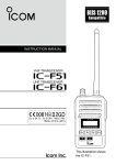
User Manual
IPL 3000
2
IPL 3000 user manual
Manual
IPL 3000
Please read this manual carefully before attempting to install an IPL 3000.
IPL 3000 user manual
3
Every effort has been made to ensure that the contents
of this manual are correct. MSS Professional does not
accept any liability for loss or damage caused or alleged
to be caused directly or indirectly by this manual. The
contents of the manual may be subject to change
without notice. MSS Professional makes no warranty of
any kind with regards to this material
© 2005 MSS Professional
Reproduction in any matter whatsoever without the written permission of MSS Professional is strictly forbidden.
Smokecloak is a registered trademark
Smokecloak is protected by
Patent Nos. 2270396, 5394139, 0659293 and 93/6722.
February 2005. Ref. MSS590C
MSS Professional A/S
Brunbjergvej 6
8240 Risskov
Denmark
Telefon+45 7217 0011
Fax
+45 8617 0055
MSS Professional Ltd.
Rectory Court, High Street
Kislingbury
Northampton
Northants
NN7 4AG
England
Phone +44 (0)1604 839000
Fax
+44 (0)1604 832666
4
IPL 3000 user manual
Contents
Safety information............................................................... 4
Preparation for use.............................................................. 7
Lamp............................................................................... 10
Installation........................................................................ 12
Service............................................................................. 13
Specifications.................................................................... 14
Strobe connections to a Smokecloak..................................... 15
Parallel connections............................................................ 16
Strobe measurements......................................................... 17
Contents
5
Warning: This product is for professional use only! It
is not for household use.
The IPL 3000 presents risks of lethal or severe
injury due to fire and heat, electric shock,
ultraviolet radiation, and falls. Flashing light is
also known to trigger epileptic seizures in persons
who are photosensitive. Read this manual before
powering or installing the fixture, follow the safety
precautions listed below and observe all warnings in
this manual and printed on the fixture.
To guard against electric shock
• Disconnect the fixture from AC power and allow
the flash capacitor to discharge for 1 minute before changing the lamp or fuse, and when not in use.
• Always ground (earth) the fixture electrically.
• Use only a source of AC power that complies with
local building and electrical codes and has both
overload and ground-fault protection.
• Do not expose the fixture to rain or moisture.
• Replace the lamp only as described or have it
replaced by a MSS Professional technician.
6
Safety information
To guard against UV radiation, burns, and fire
• Never operate the fixture with the front glass
open, missing or damaged.
• Do not stare directly into the light. Never look at
an exposed lamp while it is lit.
• Replace the lamp when it becomes defective or
worn out.
• When replacing the lamp, allow the fixture to cool
for at least 10 minutes before opening the fixture
or removing the lamp.
• Never attempt to bypass the fuse.
Always replace defective fuses with ones of the specified type and rating.
• Verify that the power feed cable is rated for the
current draw of all connected fixtures.
• Keep all combustible materials (for example
fabric, wood, paper) at least 0.5 metres (20 inches)
away from the fixture. Keep flammable materials
well away from the fixture.
• Do not illuminate surfaces within 1 metre (39
inches) of the fixture.
• Provide a minimum clearance of 0.1 metres (4
inches) around air vents.
• Never place filters or other materials over the front
glass cover.
• The exterior of the fixture can reach temperatures
up to 120° C (248° F). Allow the fixture to cool for
at least 15 minutes before handling.
• Do not modify the fixture or install other than
genuine MSS Professional parts.
• Do not operate the fixture if the ambient air
temperature (Ta) exceeds 40° C (104° F).
Safety information
7
To guard against epileptic seizure
• Do not operate the fixture near stairways.
• Provide advance notice that strobe lighting is in use.
- See label below.
8
Preparation for use
UNPACKING
The IPL 3000 comes with the following items:
• Philips XOP 15-OF or Xenon lamp (installed)
• Mounting bracket
• User manual
The packing material protects the fixture during
shipment; always use it to transport the fixture.
AC POWER CONNECTION
The auto-ranging power supply automatically adjusts
to any 50 - 60 Hz AC power supply from 125 to 260
volts. No adjustment is necessary.
The current required by the IPL 3000 varies according
to power mode, and usage.
Use 2.5 mm2 (13 AWG) or larger power feed cables
and keep runs as short as possible.
The mains lead must be fitted with a heavy duty cord
cap with ground connection.
Consult a qualified electrician if you have any doubts
about proper installation.
Preparation for use
9
Following the cord manufacturer’s instructions,
connect the yellow and green wire to ground
(earth), the brown wire to live, and the blue wire
to neutral. The table below shows some pin
identification schemes.
Table 1: Cord cap wiring
INSTALLATION
Before installing, verify that
• the fixture will be located at least 1 meter (39
in.) away from the surface to be illuminated, at
least 0.5 meters (20 in.) from any combustible
materials, and well away from flammable
materials;
• the clearance around the air vents is at least 0.1
meters (4 in.), and
• no one is located under the work area.
10
Specifications
The IPL 3000 may be installed in any orientation. The
mounting bracket provides five 12 mm holes for direct
fastening.
To install the mounting bracket
1 Place the fixture face down on a table.
2Place a plastic washer on each mounting bracket stud.
3 Place one end of the bracket on on of the mounting studs. Bend the other end of the mounting bracket,
open slightly and work it onto the opposite stud.
4P
lace a hand knob on each stud. Tighten both hand knobs to lock the mounting bracket in place.
Specifications
11
This section describes how to replace the lamp.
The lamp is electronically regulated to prevent
overheating.
LAMP REPLACEMENT
End of life can be confirmed with the flash LED on
the rear panel. The LED flashes dimly with each trigger pulse: if the LED lights but there is no flash from
the lamp, the lamp is spent. If the LED does not
flash, their may be a problem with the control signal.
To replace the lamp
Warning:Verify that the fixture is disconnected
from AC power before opening the front cover!
1 Very important: Before opening the unit, disconnect from mains electricity and wait for at least 1
minute for the capacitor to discharge.
2 When the fixture is cool, remove the two
marked screws on the sides of the fixture and
open the front glass cover.
3D
isconnect the lamp wires at the screw terminals. Lift the old lamp out of the holder.
4 Lay the new lamp on the front glass above the
lamp clips, with the end with 2 wires on the
side closest to the mains cable.
12
Lamp
5 Important! Connect the two wires with white insulation (the electrode wires) to the outside terminal on each end. Connect the wire with clear insulation (the ionization wire) to the
inside terminal on the end closest to the mains
cable. Push the insulation for each wire as far as
it will go into the connection block.
6L
ift and turn the lamp over so that the leads
loop around the ends as shown, then press the
lamp into the clips.
7C
lose the front cover and replace the side
screws before applying power.
Lamp
13
This section describes how the IPL 3000 operates
STAND-ALONE FLASH RATE
To program stand-alone execution
1 Apply power to the fixture.
2 Set pin 1 of the Mode DIP switch to ON. Set pins
2 - 5 to OFF. Set pin 6 to ON for low-power operation or to OFF for high-power operation.
3 Select Flash rate.
DIP-switch settings for security use:
50 Hz
60 Hz
Address
Mode
Address
Mode
4 Set DIP switch pin 10 to OFF for normally off operation, or to ON for normally on operation.
14
Installation
Warning: High voltage! Do not remove the rear panel.
There are no userserviceable parts inside.
FUSE REPLACEMENT
The IPL 3000 uses a 20 amp time-delay fuse for
protection against current overload. If the power
diode does not light when power is applied, the fuse
may have failed. If the fuse blows repeatedly, there
is a fault with the unit that requires service by a MSS
Professional technician.
Never bypass the fuse or replace it with one of
another size or rating.
Replacement fuses may be ordered by P/N 05020040.
To replace the fuse
1 Disconnect the fixture from AC power.
2U
nscrew the fuse holder, located on the side plate
nearest the power cord. Remove the failed fuse
from the holder and replace it with an identical
20 amp 6.3 x 32 mm time-delay fuse.
3R
eplace the fuse holder in the side plate.
Service
15
PHYSICAL
Size (without bracket):..............245 x 425 x 240 mm (9.7 x 16.7 x 9.5 in)
Weight: . ................................................................... 7.5 kg (16.5 lb)
THERMAL
Maximum ambient temperature:.................................... 40° C (104° F)
CONTROL
Signal input:................................. Switch or relay between Pin 1 and 3
AC SUPPLY
AC input:.........................................................2.5 mm2 trailing cable
AC voltage and frequency range
(XOP 15-OF model):..............................................125 - 260 V, 50 - 60 Hz
Peak current consumption: ........................................................33 A
Typical current consumption (XOP 15-OF, high power mode):........... 8 A
FUSES
Primary fuse:.........................................20 AT / 250 V, P/N 05020040
CONSTRUCTION
Housing:................................................................................. steel
Finish:...........................................electrostatic powder coating, black
MOUNTING
Minimum distance to combustible materials:.................... 0.5 m (20 in)
Minimum distance to illuminated surfaces:...........................1 m (39 in)
Minimum clearance around fan and air vents:.......................0.1 m (4 in)
16
Specifications
Smokecloak interface board System units
Strobe 3 pin IN socket.
Smokecloak interface board Vali units
The Strobe can be connected directly to the alarm panel or to the
Smokecloak. When pins 1 and 3 (N/O) are connected together the strobe
will activate. If the Smokecloak option of separate mains failure output (23-24) is not being used, connect as above. If the separate mains
failure output is being used, then trigger the strobe by using an output from
the alarm panel.
Strobe Connections to a Smokecloak
17
Smokecloak interface board System units
Strobe 1:
3 pin IN and OUT socket
Strobe 2:
3 pin IN and OUT socket
Smokecloak interface board Vali units
If you use more than 1 Strobe they can be linked via the 3 pin OUT
socket to next 3 pin IN socket.
18
Parallel connection
Parallel connection
19
Supplier:
Januar 2010
Contact:
MSS Professional A/S
Brunbjergvej 6
DK - 8240 Risskov
Phone +45 7217 0011
Fax +45 8617 0055
MSS Professional Ltd.
Rectory Court
High Street
Kislingbury
UK - Northants, NN7 4AG
Phone +44 (o) 1604 839 000
Fax
+44 (0) 1604 832 666
www.smokecloak.com