1
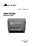
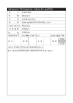
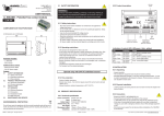
User's Manual
PBM4
PBM MONITOR
R
LTO
www.altoproaudio.com
Version 1.0 April 2005
English
the recommended fuse type as indicated in this manual.
Do not short-circuit the fuse holder. Before replacing the
fuse, make sure that the product is OFF and disconnected
from the AC outlet.
SAFETY RELATED SYMBOLS
CAUTION
RISK OF ELECTRIC SHOCK
DO NOT OPEN
Protective Ground
This symbol, wherever used, alerts you to the presence of un-insulated and dangerous voltages within the product enclosure. These are voltages that
may be sufficient to constitute the risk of electric
shock or death.
Before turning the product ON, make sure that it is
connected to Ground. This is to prevent the risk of
electric shock.
Never cut internal or external Ground wires. Likewise,
never remove Ground wiring from the Protective Ground
Terminal.
This symbol, wherever used, alerts you to important operating and maintenance instructions.
Please read.
Operating Conditions
Always install in accordance with the manufacturer's
instructions.
Protective Ground Terminal
To avoid the risk of electric shock and damage, do not
subject this product to any liquid/rain or moisture. Do
not use this product when in close proximity to water.
AC mains (Alternating Current)
Hazardous Live Terminal
ON:
Denotes the product is turned on.
Do not install this product near any direct heat source.
OFF: Denotes the product is turned off.
Do not block areas of ventilation. Failure to do so could
result in fire.
Keep product away from naked flames.
WARNING
Describes precautions that should be observed to
prevent the possibility of death or injury to the user.
IMPORTANT SAFETY INSTRUCTIONS
CAUTION
Read these instructions
Describes precautions that should be observed to
prevent damage to the product.
Follow all instructions
Keep these instructions. Do not discard.
Heed all warnings.
WARNING
Only use attachments/accessories specified by the
manufacturer.
Power Supply
Ensure that the mains source voltage (AC outlet) matches
the voltage rating of the product. Failure to do so could
Power Cord and Plug
result in damage to the product and possibly the user.
Unplug the product before electrical storms occur and
when unused for long periods of time to reduce the risk of
Do not tamper with the power cord or plug. These are
designed for your safety.
electric shock or fire.
If the plug does not fit your AC outlet seek advice from a
qualified electrician.
Do not remove Ground connections!
External Connection
Always use proper ready-made insulated mains
cabling (power cord). Failure to do so could result
in shock/death or fire. If in doubt, seek advice from
Protect the power cord and plug from any physical
stress to avoid risk of electric shock.
Do not place heavy objects on the power cord. This
could cause electric shock or fire.
a registered electrician.
Cleaning
Do Not Remove Any Covers
Within the product are areas where high voltages may
present. To reduce the risk of electric shock do not remove
any covers unless the AC mains power cord is removed.
When required, either blow off dust from the product or
use a dry cloth.
Do not use any solvents such as Benzol or Alcohol.
For safety, keep product clean and free from dust.
Covers should be removed by qualified service
personnel only.
Servicing
No user serviceable parts inside.
Refer all servicing to qualified service personnel only. Do
not perform any servicing other than those instructions
contained within the User's Manual.
Fuse
To prevent fire and damage to the product, use only
1
PREFACE
Dear customer
Thank you for choosing the
endeavours.
For the
LTO PBM SERIES MONITOR - PBM4, which is the result of our
LTO AUDIO TEAM's
LTO AUDIO TEAM, music and audio are more than a profession, it is a passion and an obsession!
We have, in fact, been designing professional audio products for a number of years in cooperation with many of the
world's major brands.
The LTO line represents unparalleled analogue and digital products made by musician, for musicians. With our design centres in Italy, the Netherlands, and United Kingdom we provide you with world-class designs, while our software
development teams continue to develop an impressive range of audio specific algorithms.
By purchasing our LTO products you become the most important member of our LTO AUDIO TEAM. We would
like to share with you our passion for what we design and invite you to make suggestions, which will aid us in developing future products for you. We guarantee you our commitment for quality, continual research and development, and
of course the best prices.
The LTO PBM4 is extremely flexible, ultra-low noise, which is configured with four MIC/line inputs channels, each
of them is equipped with a variety of key features including a 2-band equalizer, one AUX send and level control etc..
Besides, the miraculous DSP with 16 presets and powerful digital power amplifier will meet your requirements.
We would like to thank all the people who made the LTO PBM4 possible, especially to our designers and LTO
staff. It is their passion for music and professional audio that has made it possible for us to offer you, our most important
team member, our continued support.
Thank you very much
LTO AUDIO TEAM
2
TABLE OF CONTENTS
1. INTRODUCTION.....................................................................................................................................4
2. FEATURES..............................................................................................................................................4
3. QUICK START..........................................................................................................................................5
4. CONTROL ELEMENTS...........................................................................................................................6
4.1 MONO INPUT CHANNELS
4.2 +15V PHANTOM POWER SWITCH
4.3 LEVEL CONTROL
4.4 DSP/FX AUX1 POST CONTROL
4.5 EQUALIZER
4.6 TAPE IN
4.7 TAPE OUT
4.8 GRAPHIC EQ
4.9 MAIN MIX LEVEL CONTROL
4.10 MAIN MIX LEVEL LED
4.11 OPERATING LED
4.12 POWER AMPLIFIER OUTPUT
4.13 MONITOR OUTPUT
4.14 MONITOR LEVEL CONTROL
4.15 FOOTSWITCH
4.16 FX RETURN
4.17 FX SEND
4.18 DSP SECTION
4.19 REAR PANEL
5. INSTALLATION AND CONNECTION.......................................................................................................9
5.1 AUDIO CONNECTIONS
6. PRESET LIST..........................................................................................................................................11
7. TECHNICAL SPECIFICATION...............................................................................................................12
8. BLOCK DIAGRAM.................................................................................................................13
9. WARRANTY...........................................................................................................................................14
3
1. INTRODUCTION
Thank you very much for expressing your confidence in LTO products by purchasing LTO PBM4. The PBM4 is
professional monitor, which provides the state of the art digital amplifier technology specifically. You will get the smooth,
accurate, more natural and open sound from this apparatus, it is really ideal for small gigs, recording and fixed PA
installations.
The PBM4 is packed with some key features. For example: there is four MIC/line inputs which provided with ultra low
noise microphone pre-amplifiers and phantom power at +15V, each of them features a 2-band equalizer, one AUX
send and level control. FX send and return, power amplifier outputs, monitor output plus Tape in/out and level controls,
graphic equalizer for MAIN/MONITOR outputs, 16-position multi-effect and so on.
Though your PBM4 is very easy to operate, we strongly recommend you to go through each section of this manual
carefully, in this way you will get the best out of your PBM4.
2. FEATURES
The PBM4 is designed for professional application. It provides the following features:
Digital amplifier technology, offering high power and a very dynamic sound
7-band graphic EQ for MAIN/MONITOR
4 MIC/line input channels with balanced XLR and TRS inputs
Ultra-low noise discrete MIC pre-amps with +15V phantom power
2-band EQ on mono input channels
Each input channel with level control
FX send for built-in or external effects, on-stage monitor mix
Tape in/out
16-preset digital effect processor
POWER OUTPUT: 150Wrms@8Ohm
4
3. QUICK START
3.1 Please check the AC voltage available in your country before connecting your PBM4 to the AC socket.
3.2 Be sure that the main power is turned off before connecting the monitor to the AC socket. Also, you should make
sure that all input and output controls are turned down. This will avoid damage to your speakers and avoid excessive
noise.
3.3 Please connect one side of the passive speaker cable to the POWER AMPLIFIER OUTPUT of your PBM4,
and the other side to the input of your passive speaker cabinet.
3.4 Complete these connections as illustrated.
3.5 Before connecting and disconnecting the PBM4 always turn off the power switch.
3.6 Do not use solvents to clean your PBM4. A dry and clean cloth will be OK.
1
2
POWER AMPLIFIER
OUTPUT
( MIN. LOAD
8 )
Passive speaker 2
5
-
+10dB
+10dB
8
8
8
6
M
M
+10dB
+10dB
+10dB
CH 5-6
CH 4
CH 3
CH 2
TAPE IN
LEVEL
+10dB
CH 1
OFF
ON
PHANTOM
-
MONITOR
-
0
dB
TAPE OUT
3
1
RE
A
LINE IN (bal.)
LOW NOISE P
2
AUX1
POST
DSP/FX
+15dB
LEVEL
0
dB
0dB
80Hz
LOW
MIC IN (bal.)
3
1
-
-
-15dB
0dB
+15dB
12KHz
HIGH
MIC IN (bal.)
P
MIC IN (bal.)
P
MIC IN (bal.)
2
RE
A
LINE IN (bal.)
LOW NOISE P
P
3
1
+10dB
+10dB
AUX1
POST
DSP/FX
+15dB
M
P
3
2
RE
A
LINE IN (bal.)
LOW NOISE P
0
dB
0dB
80Hz
LOW
-15dB
0dB
M
1
8
LEVEL
8
RE
A
-
-
-15dB
8
LINE IN (bal.)
+10dB
+10dB
AUX1
POST
DSP/FX
+15dB
0dB
+15dB
12KHz
HIGH
8
LEVEL
0
dB
0dB
80Hz
LOW
-15dB
0dB
8
LOW NOISE P
-
-
-15dB
0dB
+15dB
12KHz
HIGH
1K
2.5K
6.3K
16K
14
12
13
11
15
9
8
2
7
3
6
5
4
( MIN. LOAD
0
10
8
)
2
-30
-10
1.
2.
3.
4.
5.
6.
7.
8.
9.
10.
11.
12.
13.
14.
15.
16.
WARM HALL
BRIGHT HALL
WARM ROOM
BRIGHT ROOM
VOCAL 1
VOCAL 2
VOCAL 3
PLATE
STEREO DELAY1
STEREO DELAY2
REV + DELAY1
REV + DELAY2
REV + DELAY3
REV + DELAY4
REV + CHORUS1
REV + CHORUS2
PRESETS
MONITOR OUT
MUTE
CLIP
AUX/DFX RET
DSP
MUTE
POWER AMPLIFIER
OUTPUT
1
PRESETS
10
16
1
DSP
15
15
400
9
9
160
0
0
63
9
9
0
15 10
15
R
LTO
LEVEL
+10dB
FOOTSWITCH
FX RETURN
FX SEND
-
0
dB
OPERATING
MAIN
PBM4
8
2
AUX1
POST
DSP/FX
+15dB
80Hz
LOW
-15dB
0dB
8
LEVEL
0
dB
0dB
0dB
+15dB
12KHz
HIGH
8
-
-15dB
-15dB
0dB
4. CONTROL ELEMENTS
1
4.1 MONO INPUT CHANNELS
There are CH1 through CH4, which comes with balanced
MIC IN and LINE IN connectors. Use the XLR (MIC IN)
socket to connect low impedance microphone or low level
signal, which also features +15V phantom power allowing
you to connect condenser microphone. Use the 1/4" TRS
(LINE IN) jack to connect either a microphone or a line level
instrument such as synthesizers, drum machines, effect
processors or any other line level signal.
0dB
HIGH
5
12KHz
+15dB
-15dB
0dB
LOW
80Hz
-15dB
6
+15dB
0dB
DSP/FX
Note: You shall never connect an unbalanced microphone
to the XLR socket if you do not want to damage both
the microphone and the monitor.
-
8
AUX1
POST
0
dB
3
+10dB
8
-
LEVEL
LINE IN (bal.)
LOW NOISE P
RE
A
M
P
This switch will apply +15 Volt Phantom Power only to the
4 XLR inputs sockets. When these XLR sockets are connected with devices that do not require Phantom Power,
please make sure the Phantom Power is turned off, otherwise, this may damage the device and monitor.
.
2
1
1
3
4.3 LEVEL CONTROL
+10dB
2
4.2 +15V PHANTOM POWER SWITCH
4
3
This control is used to adjust the overall level of respective
channel. The adjustable range goes from - to +10dB.
MIC IN (bal.)
CH 1
4.4 DSP/FX AUX1 POST CONTROL
4
This control is configured as POST-FADER, so the audio
signal will be affected by channel level control. Via the FX
SEND socket, the AUX1 signal can be sent to an external
effect device.
4.5 EQUALIZER
0
dB
HIGH
15
-
8
Your PBM4 features a 2-band equalizer allowing you to adjust
the high and low frequencies separately on each mono
channel. Both bands provide up to +15dB of boost or cut.
+10dB
MONITOR
5
-
LOW
6
PHANTOM
This is the bass control. It is used to boost male voice or
kick-drum and bass guitar. Your system will sound much
bigger than what it is. The gain range goes from -15dB to
+15dB and the center frequency is 80Hz.
4.6 TAPE IN
8
This is the treble control. You can use it to get rid of high
frequency noises or to boost the sound of cymbals or the
high harmonics of the human voice. The gain range goes
from -15dB to +15dB with a center frequency of 12kHz.
+10dB
LEVEL
ON
2
OFF
TAPE IN
7
7
8
Your PBM4 features dual RCA jacks (left and right). If you
wish to listen to your monitor from a tape recorder, DAT
or cassette, please use these tape input jacks.
7
TAPE OUT
CH 5-6
8
4.7 TAPE OUT
Via these jacks, you can route the main out signal into a tape recorder or DAT for recording.
MAIN
15
15 10
9
9
0
0
9
9
15
15
12
OPERATING
9
0
11
0
dB
-10
LEVEL
10
-
63
22
160
400
DSP
21
1
16
6.3K
PRESETS
1.
2.
3.
4.
5.
6.
7.
8.
9.
10.
11.
12.
13.
14.
15.
16.
MUTE
4
5
13
6
12
7
11
10
9
8
0
10
PRESETS
AUX/DFX RET
1
2
+10dB
16K
CLIP
3
14
19
2.5K
DSP
MUTE
2
15
1K
8
-30
WARM HALL
BRIGHT HALL
WARM ROOM
BRIGHT ROOM
VOCAL 1
VOCAL 2
VOCAL 3
PLATE
STEREO DELAY1
STEREO DELAY2
REV + DELAY1
REV + DELAY2
REV + DELAY3
REV + DELAY4
REV + CHORUS1
REV + CHORUS2
18
FX SEND
17
FX RETURN
20
13
16
POWER AMPLIFIER
OUTPUT
( MIN. LOAD
8
MONITOR OUT
FOOTSWITCH
)
14
4.8 GRAPHIC EQ
9
Your PBM4 is equipped with a graphic equalizer, and provides 7-band fader controls. Via these faders, you can
boost or attenuate the selected frequency by 15dB at a preset bandwidth. When all faders are at the center
position, the output of the equalizer is flat response. They are used to modify the frequency "contour" of a
sound. The EQ function will be activated automatically as soon as you operate your PBM4.
10
4.9 MAIN MIX LEVEL CONTROL
This control is used to adjust the overall volume of main mix output.
11
4.10 MAIN MIX LEVEL LED
The 4-segment LED meter is used to indicate the main mix output level.
4.11 OPERATING LED
12
This LED indicates when the power is switched on in your PBM4.
4.12 POWER AMPLIFIER OUTPUT
13
The both jacks are used to output the main mix signal to external passive speaker, the minimum load is 8 ohms.
14
4.13 MONITOR OUTPUT
This jack is used to connect the input of external monitor amplifier or active monitor speaker.
4.14 MONITOR LEVEL CONTROL
15
This control is used to adjust the level of monitor output.
4.15 FOOTSWITCH
16
You can connect an external footswitch to turn on/off the onboard effect module. It is a 1/4 " phone jack.
8
17
4.16 FX RETURN
This jack is used to return the sound of an effect unit to the main mix. You can also use it as the extra auxiliary
inputs.
4.17 FX SEND
18
This jack is used to send out the signals from AUX bus.
4.18 DSP SECTION
Your PBM4 features the special 16-preset digital effect, further details please refer to following content.
- PRESETS
19
Adjust this knob to select the right effect you wish to perform. There are total 16 options for you: WARM HALL,
BRIGHT HALL, WARM ROOM, BRIGHT ROOM, VOCAL 1, VOCAL 2, VOCAL 3, PLATE, STEREO DELAY1,
STEREO DELAY2, REV + DELAY1, REV + DELAY2, REV + DELAY3, REV + DELAY4, REV + CHORUS1 and
REV + CHROUS2.
- AUX/DFX RET
20
This control is used to adjust the volume of FX RETURN.
- DSP MUTE
21
This switch is used to activate/deactivate the effect facility. Sometimes, you can also use the FOOTSWITCH
jack for convenient operation.
- CLIP/MUTE LED
22
This LED lights up when the input signal is too strong. In case of the digital effect module being muted, this LED
also lights up.
4.19 REAR PANEL
- POWER ON/OFF
23
This switch is used to turn the main power ON/OFF.
- AC INLET with FUSE 2A
POWER
ON
24
Use it to connect your PBM4 to the main AC with the
supplied AC cord.
Please check the voltage available in your country
and how the voltage for your PBM4 is configured
before attempting to connect your PBM4 to the main
AC.
OFF
23
FUSE 2A
AC~230V
50/60Hz
24
5. INSTALLATION AND CONNECTION
Ok, you have got to this point and you are now in the position to successfully operate your PBM4. However, we advise
you to read carefully the following section to be the real master of your own monitor. Not paying attention enough to
the input signal level, to the routing of the signal and the assignment of the signal will result in unwanted distortion, a
corrupted signal or no sound at all. So you should follow this procedure for every single channel.
Turn down all input and output controls.
Connect phantom powered microphones before switching on the +15Volt phantom power switch.
Set the output level of your PBM4 at no more than 75%.
Now, set the MONITOR level at no more than 50%. In this way you will be able to hear later what you are
doing by connecting a pair of powered monitor speakers.
Position EQ controls on middle position.
Now repeat the same sequence for all input channels. The main LED meter could move up into the red
section. In this case you can adjust the overall output level through the MAIN MIX LEVEL control.
9
5.1 AUDIO CONNECTIONS
You can connect unbalanced equipment to balanced inputs and outputs. Simply follow these schematics.
Ring=Right Signal
Tip
Sleeve
Ring
Strain Clamp
Tip=Left Signal
Sleeve=Ground/Screen
Use for Headphone
1/4" Stereo (TRS) Jack Plug
Sleeve
Tip
Tip=Signal
Strain Clamp
Sleeve=Ground/Screen
Use for Mono Line In, Mono 1/4"Jack Plugs
1/4" Mono (TS) Jack Plug
Sleeve
Ring=Return Signal
Tip
Ring
Strain Clamp
Tip=Send Signal
Sleeve=Ground/Screen
Use for Insert Points
1/4" Stereo (TRS) Jack Plug
2=Hot(+)
2
1
3
2=Hot(+)
1=Ground/Screen
3=Cold(-)
2
1
3
1=Ground/Screen
3=Cold(-)
Use for Balanced Mic Inputs
(For unbalanced use, connect pin 1 to 3)
Use for Main output
(For unbalanced use, leave pin 3 unconnected)
3-pin XLR Male Plug
3-pin XLR Line Socket
(seen from soldering side)
(seen from soldering side)
10
6. PRESET LIST
No.
Description
Preset
parameter
1
WARM HALL
Simulate a small acoustic space of the sound.
Rev. Decay time: 360ms
Pre-delay: 45ms
2
BRIGHT HALL
Simulate a large acoustic space of the sound.
Rev. decay time: 290ms
Pre-delay: 23ms
3
WARM ROOM
Simulate a small acoustic space of the sound.
Rev. decay time: 210ms
Pre-delay: 45ms
4
BRIGHT ROOM
Simulate a studio room with many early reflections.
Rev. Decay time: 210ms
Pre-delay: 23ms
5
VOCAL 1
Simulate a room with without delay time.
Rev. decay time: 450ms
6
VOCAL 2
Simulate a room with small delay time.
Rev. decay time:240ms
Pre-delay: 25ms
7
VOCAL 3
Simulate a small space with slight decay time.
Rev. decay time:100ms
Pre-delay: 114ms
8
PLATE
Simulate the transducers sound like classic bright vocal
plate.
Pre-delay: 10ms
Rev. decay time: 290ms
9
STEREO DELAY 1
Recreate the input sound on the stereo output with different
time.
Period: 352ms
10
STEREO DELAY 2
Recreate the input sound on the stereo output with different
time.
Period: 238ms
11
REV + DELAY 1
Delay with room effect.
Delay period: 326ms
Rev. decay time: 290ms
12
REV + DELAY 2
Delay with room effect.
Delay period: 211ms
Rev. decay time: 240ms
13
REV + DELAY 3
Delay with room effect.
Delay period: 375ms
Rev. decay time: 210ms
14
REV + DELAY 4
Delay with room effect.
Delay period: 277ms
Rev. decay time: 150ms
15
REV + CHORUS1
Simulate the sound effect achieved by rotating horn speakers
and a bass cylinder.
Chorus rate: 3.67Hz
Rev. decay time: 290ms
16
REV + CHORUS2
Simulate the sound effect achieved by rotating horn speakers
and a bass cylinder.
Chorus rate: 3.02Hz
Rev. decay time: 150ms
11
7. TECHNICAL SPECIFICATION
Input channels
Impedances
Equalization
DSP Section
Main Mix Section
Amplifier Section
Power supply
Microphone Input
Frequency response
Distortion(THD&N)
Gain
SNR(Signal to Noise Ratio)
Line input
Frequency response
Distortion(THD&N)
Gain
Microphone Input
Channel Insert return
All other inputs
Tape out
All other outputs
Hi shelving
Low shelving
A/D and D/A converters
DSP resolution
Type of effects
2.5kOhm
10kOhm or greater
1kOhm
120Ohm
+/-15dB@12kHz
+/-15dB@80Hz
24bit
24bit
HALL, ROOM, VOCAL, PLATE, STEREO DELAY
REV+DELAY, and REV+CHORUS combinations
Presets
Controls
16
16-position PRESET selector
CLIP LED
MUTE SWITCH with LED indicator
Fader 0 dB, channels muted: -85dBr (ref.: +4dBu)
Fader 0 dB, all input channels assigned and set to
UNITY gain: -81dBr(ref.: +4dBu)
+22dBu unbalanced, 1/4"jacks
+22dBu
150W RMS (Nominal power)
Noise(Bus noise)
MONITOR max out
FX Sends max out
Output Power
Frequency Response
Output Impedance
Main voltage
25HZ-20KHZ
8 ohm
USA/Canada
Europe
100 120V~, 60Hz
210 240V~, 50Hz
Dimensions
Net Weight
Shipping Weight
U.K./Australia
240V~, 50Hz
260 watts
100-120V~: T4A
21 0-240V~: T2A
216.5x143.5x152.5mm(LxWxH)(8.5"x5.6"x6")
9.5kg
11.34 kg
Volume
2.8CFT
Power Consumption
Fuse
Physical
Electronically balanced, discrete input configuration
10Hz to 55kHz, +/- 3dB
0.05% at +4dBu, 1kHz
30dB
>94dB
Electronically balanced
10Hz to 55kHz, +/- 3dB
0.05% at +4dBu, 1kHz
10dB
1.4kOhm
12
8. BLOCK DIAGRAM
13
9. WARRANTY
1. WARRANTY REGISTRATION CARD
To obtain Warranty Service, the buyer should first fill out and return the enclosed Warranty Registration Card within
10 days of the Purchase Date.
All the information presented in this Warranty Registration Card gives the manufacturer a better understanding of
the sales status, so as to purport a more effective and efficient after-sales warranty service.
Please fill out all the information carefully and genuinely, miswriting or absence of this card will void your warranty
service.
2. RETURN NOTICE
2.1 In case of return for any warranty service, please make sure that the product is well packed in its original shipping
carton, and it can protect your unit from any other extra damage.
2.2 Please provide a copy of your sales receipt or other proof of purchase with the returned machine, and give detail
information about your return address and contact telephone number.
2.3 A brief description of the defect will be appreciated.
2.4 Please prepay all the costs involved in the return shipping, handling and insurance.
3. TERMS AND CONDITIONS
3.1
LTO warrants that this product will be free from any defects in materials and/or workmanship for a period
of 1 year from the purchase date if you have completed the Warranty Registration Card in time.
3.2 The warranty service is only available to the original consumer, who purchased this product directly from the
retail dealer, and it can not be transferred.
3.3 During the warranty service, LTO may repair or replace this product at its own option at no charge to you for
parts or for labor in accordance with the right side of this limited warranty.
3.4 This warranty does not apply to the damages to this product that occurred as the following conditions:
Instead of operating in accordance with the user's manual thoroughly, any abuse or misuse of this product.
Normal tear and wear.
The product has been altered or modified in any way.
Damage which may have been caused either directly or indirectly by another product / force / etc.
Abnormal service or repairing by anyone other than the qualified personnel or technician.
And in such cases, all the expenses will be charged to the buyer.
3.5 In no event shall LTO be liable for any incidental or consequential damages. Some states do not allow the exclusion or limitation of incidental or consequential damages, so the above exclusion or limitation may not apply to you.
3.6 This warranty gives you the specific rights, and these rights are compatible with the state laws, you may also
have other statutory rights that may vary from state to state.
14
SEIKAKU TECHNICAL GROUP LIMITED
SEKAKU ELECTRON INDUSTRY (H.K.) CO., LTD.
No. 1, Lane 17, Sec. 2, Han Shi West Road, Taichung 40151, Taiwan
http://www.altoproaudio.com Tel: 886-4-22313737
email: [email protected] Fax: 886-4-22346757
All rights reserved to ALTO. All features and content might be changed
without prior notice. Any photocopy, translation, or reproduction of part of this
manual without written permission is forbidden. Copyright c 2005 SEIKAKU GROUP
NF02055-1.0