1
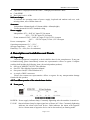
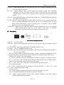
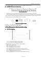
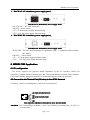
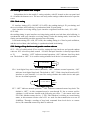
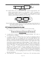
302
MODEL7
MODEL7302
FE1 Optic Fiber Modem
User Manual
Shenzhen 3onedata Technology Co.,Ltd
Tel: +86-755-26702688 Fax: +86-755-26703485
www.3onedata.com
MODEL7302 User Manual
Contents
1. Introduction..........................................................................................................................................3
2. Product Features...............................................................................................................................3
3. Specifications..................................................................................................................................... 4
4. Description on Installation and Panels..................................................................................4
4.1 Unpacking:
Unpacking:..................................................................................................................................... 4
4.2 Front/Rear panels of the stand alone device:
device:.......................................................................5
4.3 Front/Rear panels of Rack-mountable casing:
casing:.....................................................................6
5. MODEL7302 Application................................................................................................................7
5.1 E1 configuration
configuration........................................................................................................................... 7
5.2 Connection the Twisted Pair(120 ohm) to the G.703 Network
Network.......................................... 8
5.3 Settings of Switch and Jumper
Jumper................................................................................................ 8
5.3.1 Clock setting
setting.......................................................................................................................... 8
5.3.2 Settings of loop back test and pseudo-random code test
test................................................... 8
5.3.3 Framing/non-framing and time slot settings
settings...................................................................... 9
6. Common Problems........................................................................................................................ 10
Page 2 of 10
MODEL7302 User Manual
1. Introduction
MODEL7302 FE1 Fiber Modem is a high-performance E1 fiber optic modem developed by
using a dedicated integrated circuit. It is to modulate a framing or non-framing E1 data signal
directly into single- or multi-mode optic fiber for a transmission via optic cable line. At
another end of the optic cable, optical signal is demodulated into a framing or non-framing E1
data signal. E1 interface may be directly connected with the E1 interfaces of image and data
terminals or the WAN ports of MUX, exchanger and router for a dedicated network setup or a
LAN connection.
2. Product Features
�
�
�
�
�
�
�
�
�
�
�
�
�
�
Conforms to all relevant ITU series standards( ITU-T G.703 G.704 G.823)
Transmit one E1 channel
Framing or non-framing mode in option
E1 time slot in arbitrary option
Balanced 120Ω/non-balanced 75Ω interfaces automatic
Support the loop back of local analog/digital interface
Support remote loop back function (valid on under framing mode)
Support pseudo-random code test function, providing convenience for the test of optic
fiber line status
120km trunking -free transmission distance for single-mode optic fiber
Capable to be communicated with V.35 fiber modem
Available with complete line detection and alarm indications
Available with independent structure and 19-inch frame-mounted structure
(frame-mounted structure can be inserted with 16 modules);
AC 220V and DC –48V inputs may be selected for fiber optic modems of both structures;
For frame-mounted fiber optic modems, dual power supply heat backup is provided to
ensure a Receiving level:0~-43db
s
3. Specification
Specifications
Optic interface
interface::
�
Line mode type: CMI
�
Line mode rate: 2.048Mbps
�
Operating wavelength:850nm,1310nm or 1550nm
�
Optic fiber connector: SC/PC
�
Applicable optic fiber: multi-mode, single-mode
�
Transmission distance:
Single-mode: up to 120km Multi-mode: up to 2km
E1 interface
interface::
�
Standard: ITU-T G.703 G.704
Frame structure: framing CCS(PCM31)/ CAS(PCM30)
�
Rate:N×64Kbps (N=1~31)or 2.048Mbps
�
Page 3 of 10
MODEL7302 User Manual
Impedance:75Ω,physical interface BNC ;120Ω,physical interface RJ45
Code:HDB3
�
Receiving level:0~-43db
�
Indicator lamps
lamps::
To indicate the operating status of power supply, loopback and random code test, code
missing alarm, out-of-frame alarm etc.
Structure
Structure::
Independent:140mm(depth) x 210mm(width) x 42mm(height)
Frame-mounted:19in 4.5U standard casing
Power supply
supply::
Independent: 85V~264V AC input,5V/2A output
-36V~-72V DC input,5V/2A output
Frame-mounted: 150V~260V AC input,5V/16A,12V/1A output
-38V~ -58V DC input,5V/16A ,12V/1A output
Power consumption: 3W
Operating temperature:0° C~50° C
Storage temperature: -20° C~80° C
Humidity: 5%~90% (free of condensate)
�
4. Description on Installation and Panels
4.1 Unpacking
Unpacking::
After the equipment is unpacked, a check shall be done for the completeness. If any part
is found missing, please immediately contact our representative offices or agents. Complete
packing shall include the following items (for an independent product):
One set of MODEL7302 FE1 Fiber Modem
�
One FE1 Fiber Modem Operation Manual
�
�
One power line(FE1 Fiber Modem/AC)
�
A couple of BNC connectors
Please also contact our representative offices or agents for any transportation damage
found with this product.
4.2 Front/Rear panels of the stand alone device
device::
� Front panel
panel:
Front Panel of MODEL7302
POWER:Power supply indicator lamp. Constantly lightening after the machine is turned on.
E1 LOF:Alarm indicator lamp for input signal out-of-frame in E1 line. Constantly lightening
indicates the alarm with local device; flash indicates the alarm with opposite
device. Alarm status of opposite device can be detected only at framing mode.
Page 4 of 10
MODEL7302 User Manual
E1 LOS:Alarm indicator lamp for code missing in E1 line. Constantly lightening indicates
the alarm with local device.
FO LOF : Alarm indicator lamp of input signal out-of-frame in optic line. Constantly
lightening indicates the alarm with local device; flash indicates the alarm with
opposite device. Alarm status of opposite device can be detected only at framing
mode.
FO LOS:Alarm indicator lamp for code missing in optic line. Constantly lightening indicates
the alarm with local device.
LOOP:Indicator lamp of loopback test status. When local device is at a loopback status, the
lamp is constantly lightening; when opposite device is at a loopback status, the lamp
flashes. When local device is not at a framing mode, it is unable to detect whether
opposite device is at a loopback test status.
PTOK/CRC:Indicator lamp of Pseudo-random code test. When the device is at a loopback
status, pseudo-random code test can be made. If this lamp is constantly
lightening, it indicates that Pseudo-random code passes the test.
� Rear panel
panel:
/AC
Rear Panel of MODEL7302
MODEL7302/AC
220V AC: AC power jack.
OFF ON: Power switch. When the ON button is pressed down, the power supply is turned
on.
E1-75Ω TX/RX:Receiving/sending jack of 75ΩBNC interface in E1.
E1-120Ω: Jack of 120Ω RJ45 interface in E1.
TX RX : Receiving/sending jack of optical fiber, with TX as the sending terminal and RX as
the receiving terminal.
There is a coded switch S5 on the panel, which is used as the system configuration switch
to set such functions as clock, time slot, phase, loopback and Pseudo-random code test etc.
Wherein, S5.1 and S5.2 are clock settings.
S5.2=OFF:network clock at E1 interface(Received Recovered) (S5.1 in whatever status)
S5.1 = OFF,S5.2=ON:network clock at the optic fiber interface (Received Recovered).
Remote time slot setting can be tracked only at this status.
S5.1 = ON,S5.2=ON:using local crystal oscillation generating clock
S5.3: time slot setting
S5.3=OFF,using remote time slot setting (valid only when S5.1 = OFF,S5.2=ON)
S5.3=ON,using local time slot setting
S5.4: Reserved
S5.5: Local loopback setting (optic interface in direct loopback), ON valid.
S5.6: Local digital loopback (E1 interface loopback), ON valid.
S5.7: Remote digital loopback (remote optic interface loopback), ON valid. Valid at
framing mode (0 time slot unused).
Page 5 of 10
MODEL7302 User Manual
S5.8: Pseudo-random code test, ON valid, and valid at loopback status.
� MODEL7302 bottom coded switch
switch:
Bottom Coded Switch
After time slot 0 is valid, other coded switches in whatever positions are all valid.
Select the number of time slots according to the expected rate. Normally for an independent
type, a time slot setting of automatic tracking Central Site module is selected. Coded switches
of plate-clip time slot correspond to S1, S2, S3 and S4.
/DC
Rear Panel of MODEL7302
MODEL7302/DC
48V DC: DC -48V power supply connector
The others are the same as AC Rear Panel
4.3 Front/Rear panels of Rack-mountable casing
casing::
�
RACK front panel
panel:
Front Panel of RACK
+5V: 5V main power supply indicator lamp
+12V: 12V fan power supply indicator lamp
Under the panel is a group of indicator lamps matrix:
PWR : power supply lamp;
RXD : lightening upon data receiving;
TXD : lightening upon data sending;
LOS : lightening when the optic line or E1line gets lost;
LOF : lightening after a synchronization of data out-of-frame;
TEST : lightening during loopback test;
PTOK: lightening after a successful pseudo-random code test;
Page 6 of 10
MODEL7302 User Manual
� RACK/AC AC redundancy power supply panel
panel:
RACK/AC AC Redundancy Power Supply Panel
160~270 VAC:AC 220V input jack
ON OFF:power switch
+5V:5V main power supply indicator lamp;
+12V:12V fan power supply indicator lamp
� RACK/DC DC redundancy power supply panel
panel:
RACK/DC DC Redundancy Power Supply Panel
40~60 VDC:DC-48V input connector (FG grounded, with“- +” terminals connected with
48V input)
ON OFF: power switch
+5V: 5V main power supply indicator lamp
+12V: 12V fan power supply indicator lamp
5. MODEL7302 Application
1 E1 configuration
5.
5.1
The device support two physical match impedance of the E1 interface, which can
automatics 120ohm balanced twisted-pair and 75ohm non-balanced coaxial cable interface.
Users can select the appropriate interface to connection dispense with any operation.
2 Connection the Twisted Pair(120 ohm) to the G.703 Network
5.
5.2
As shown, 1 and 2 are sending lines, 4 and 5 are receiving lines.
1 . TX + P os itiv e e nd of da ta tra ns m is s ion
2 . TX - Ne ga tiv e e nd of da ta tra ns m is s ion
1
2
3
4
5
6
7
8
3 . Ide l
4 . RX + P os itiv e e nd of da ta re c e ption
5 . RX - Ne ga tiv e e nd of da ta re c e ption
6 . Ide l
7 . Ide l
8 . Ide l
Line Sequence of Balanced Twisted-Pair at E1 Interface RJ45
Attention
Attention: In E1 twisted-pair standard, 1 and 2 are defined as sending lines, 4 and 5 as
receiving lines.
Page 7 of 10
MODEL7302 User Manual
5.3 Settings of Switch and Jumper
Independent device has totally 5 setting switches, with S5 located on the rear panel and
S1~S4 under the bottom cover. The user can easily make settings without the need to open the
cover.
5.3.1 Clock setting
E1 interface timing (S5.1=ON/OFF, S5.2=OFF): the sending timing is E1 port timing, and
the received data, after buffering, is synchronized with E1 port timing.
Optic interface receiving timing (optic interface originated from the clock, S5.1=OFF ,
S5.2=ON):
the sending timing is optic interface receiving timing, and the received data, after buffering, is
synchronized with optic interface receiving timing. Under this timing mode, local time slot
setting can automatically track the opposite time slot setting.
Local main timing (S5.1=ON, S5.2=ON): the sending timing is of local crystal oscillation,
and the received data, after buffering, is synchronized with local timing.
5.3.2 Settings of loop back test and pseudo-random code test
S5.5 ~ S5.8 of coded switch S5 are used for setting the loop back test and pseudo-random
code test. S5.5 is local loop back control(LLOOP)and optic interface is directly looped back
to E1
interface. “OFF” indicates normal operation; “ON” indicates local loop back
test. The default is “OFF”. It is used for testing whether local device is in normal operation.
E1
F E 1 Fiber M odem
Optical
Interface
Local Loop back Schematic
S5.6: local digital loop back control (DLOOP). “OFF” indicates normal operation; “ON”
indicates local digital loop back. The default is “OFF”. With a loop back from local E1
interface to optic interface, it is used for testing whether the remote device and optic
line are in normal operation.
E1
F E 1 Fiber M odem
Optical
Interface
Local Digital Loop back
S5.7: “OFF” indicates normal operation;“ON” indicates command remote loop back. The
default is “OFF”. As this command must be sent through E1 line to remote end for
validness, it will become invalid at the following two cases: ① the remote end is not
FE1 Fiber Modem remote device; ② FE1 Fiber Modem is working at a non-framing
status, at this moment all time slots of E1 are used for data transmission at a rate of
2048Kbps. Through a sending of loop back command from local device to remote
device, the command remote loop back is achieved.
Page 8 of 10
MODEL7302 User Manual
E1
F E 1 Fiber M odem
Fiber Link
F E 1 Fiber M odem
E1
R em ote
Local
Remote Loop back
S5.8: Pseudo-random code test control (PATT). “OFF” indicates normal operation; “ON”
indicates pseudo-random sequence test. The default is “OFF”. It generates a
pseudo-random sequence code to be transmitted to E1 output terminal and tests
whether E1 input signal is in compliance with this sequence standard, so as to judge
whether the device and line transmission have an error code.
E1
F E 1 Fiber M odem
Fiber Link F E 1 Fiber M odem
Local
E1
R em ote
Pseudo-random Code Test
Remark: Pseudo-random sequence code test can be made only under a loop back status. At
this moment, constantly lightening of LOOP and PTOK/CRC lamps shows local
status, and flash shows remote status.
5.3.3 Framing/non-framing and time slot settings
Totally 32 coded switches S1, S2, S3 and S4 are used for E1 time slot setting.
E1 Time Slot Setting
�
�
�
st
1 switch (S1.1) is used for controlling E1 framing/non-framing. “ON” refers to
non-framing mode (2.048Mbps).
31 switches, from 2nd—32nd(S1.2~S1.8, S2, S3, S4), are respectively used for
controlling the selection of 1st –31st time slots. Set at “ON”, the corresponding time slot is
selected; set at “OFF”, the corresponding time slot is not selected. The rate of E1
interface is completely dependent on the number of the selected time slots. For example:
the setting of 3rd switch to “ON” and all other switches to “OFF” indicates that 2nd time
slot is selected, at this moment the rate is 64K; the setting of 7th and 8th switches to “ON”
and all other switches to “OFF” indicates that 6th and 7th time slots are selected, with a
rate of 2×64K=128K. TSO setting is used for specifying E1 frame to be transparent or
framing: “0”--framing, “1”--non-framing. But the bit has to be specified in combination
with other time slots. TS16 setting is used for controlling E1 frame structure to be
PCM30(CAS)or PCM31(CCS): ‘0’—PCM30, at this moment 16th time slot must not
be used for transmission service; ‘1’—PCM31, 16th time slot can be used for transmission
service. Besides, TS1—TS31 are respectively used for controlling the selection of
1st—31st time slots: ‘1’—the corresponding time slot is selected; ‘0’—the corresponding
time slot is not selected.
Typical application: Non-framing mode: 1st switch is set to “ON”, and all other switches
Page 9 of 10
MODEL7302 User Manual
to “OFF” (other switches are located in such a way that the setting of non-framing is
unaffected) Framing mode: 1st switch is set to “OFF”, and all other switches are set
according to the time slot positions to be used by E1 channel and the rate of V.35 port. (If
it is set to tracking remote time slot, the time slot switch will become invalid)
Attention: Ex-work S1,S2,S3 and S4 are all set to “OFF
OFF””
Attention: The setting of tracking remote time slot
lot:: S5.2 to “ON
ON””; S5.1 and S5.3 to
“OFF
OFF””
6. Common Problems
Common Failures and Solutions
No.
Failure
Cause
Solution
1
PWR
power
supply
indicator
lamp
not
lightening
1.Power
supply
not
properly connected
2.Protector tube damaged
3. -48V DC input tie-line
in reverse connection
4.Internal power supply
circuit with failure
1.Check power switch and jack 2.Replace
protector tube
3.Correct -48V power supply line
connection
4.Returned to the manufacturer for repair.
2
Optic interface LOF 1.Optic interface not clean
out-of-frame alarm lamp 2.Optic fiber not well
lightening
inserted
3.Wrong clock setting
4.Time slots of the devices
at
two
ends
not
conformance
5.Internal circuit damaged
1. Clean the connector of optic interface
2. Insert the SC connector in place
3. Refer to the description on rear panel
4. Returned to the manufacturer for repair.
3
Optic LOS data loss 1. Optic fiber in wrong
alarm lamp lightening
interconnection
2.Optic fiber not well
inserted
3.Optic fiber broken
4.Internal circuit damaged
1. Correct the connection
2. Insert the SC connector in place
3. Check optic cable
4. Returned to the manufacturer for repair.
4
Lightening
of
LOF 1.Error code in the line of 1.Check if UTP wire couple is twisted or
out-of-frame alarm lamp E1 interface
the connecting cable is not good contact
at E1 interface
2.Internal circuit damaged 2.Returned to the manufacturer for repair.
5
Lightening of LOS data 1.Line of E1 interface not 1. Check the linear sequence of UTP cable
loss alarm lamp at E1 getting through
or check if crystal head is in good
interface
2.Internal circuit damaged connection; Check if coaxial cable is
broken
2.Returned to the manufacturer for repair.
Page 10 of 10