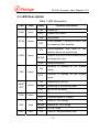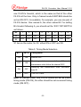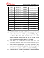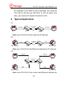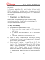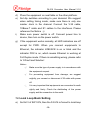
1
E1:Framed/unframed,75ohm/120ohm Compatible
F5-4511V Series V.35,10Base-T to E1 Converter
F4-516 User Manual
(Version: 1.0)
BEIJING FIBRIDGE CO., LTD.
F4-516 Converter User Manual V1.0
Table of Content
1
Overview ........................................................................3
2
Feature ...........................................................................3
3
Specification ..................................................................5
3.1
E1 interface.........................................................5
3.2
V.35 Interface ......................................................5
3.3
Ethernet interface................................................6
3.4
Size .....................................................................7
3.5
Power..................................................................7
4
Environment ..................................................................7
5
Appearance....................................................................8
5.1
Front panel of standalone....................................8
5.2
Back panel of standalone ....................................8
5.3
LED Description ..................................................9
5.4
DIP SWITCH DESCRIPTION............................ 10
6
Typical Application...................................................... 14
7
Diagnosis and Maintenance ....................................... 15
7.1
Step of installing ................................................ 15
7.2
Local Loop Back Setting ................................... 16
7.3
Diagnostic Loop Back Setting ........................... 17
7.4
Remote Loop Back Setting ............................... 18
7.5
Setting remote’s bandwidth ............................... 18
7.6
Bit error test online ............................................ 19
7.7
Selection of V.35 data and timing phase ........... 20
-1-
F4-516 Converter User Manual V1.0
7.8
Testing interface of Ethernet ............................. 20
8
Fault and Solution ....................................................... 21
9
Order Information........................................................ 23
-2-
F4-516 Converter User Manual V1.0
1 Overview
F5-4511V Series F4-516 converter gives the interface
conversion between V.35/10Base-T and G.703 E1. This device
have high performance and low price which is produced by BEI
JING FIBRIDGE Co.,Ltd. F4-516 converter can give not only
interface conversion between V.35 and G.703 E1 but also
interface conversion between 10Base-T and G.703 E1, in
addition F4-516 converter can also make 10Base-T and V.35
together and transmit used E1 channel. Its E1 data interface
also provides an economical digital access solution for E1 and
Fractional E1 network Services, which can work at data rates of
64Kbps to 2048Kbps. Timeslot assignment is accomplished
according to the Data Port speed and manual setting of DIP
switches. The main E1 link may be clocked from the recovered
receive clock, from the Data Port clock, or from an internal
oscillator. For easy to check the fault of network line, the device
provides loop selection, both local loop and remote loop.F4-516
is widely used in communication network, both in WAN and
LAN field.
2 Feature
Interface conversion between V.35/10Base-T and E1
Support ITU-T V.35, G.703, G.704, G.823
Standalone
and
chassis
hot-swap
-3-
module
available,
support
F4-516 Converter User Manual V1.0
Framed (N*64Kbps) and unframed (2.048Mbps) optional,
support continuous and discontinuous timeslots setting
Frame mode support PCM30/ PCM31
CRC/non-CRC auto-negotiation on E1 interface
Support remote bandwidth control, and remote loop back
under framed mode
Support internal clock, E1 recovery clock or V.35 line clock
Provide local loop back test, functional diagnostic loop
back test and remote loop back test
For V.35 interface, at receive side, clock is reversed and
non-reversed auto–negotiation, while at transmission side,
clock can be configured reversed or non-reversed
For E1 interface, 75 ohm (unbalanced) and 120 ohm
(balanced) available and auto-negotiation
For V.35 interface, DCE and DTE mode are optional
Ethernet Port: 10Mbps, Full/Half Duplex Mode compatible
Fully compatible with IEEE 802.3 and Ethernet Standards
10Base-T
LAN
Interface
on
RJ-45
connector
and
MDI/MDI-X available and auto-negotiation
Allow transmitting and receiving VLAN data packet
15000 frames per second filtering and forwarding rate
1000 MAC address LAN table, and automatic LAN table
learning and aging
Comprehensive LED indicators on front panel, convenient
for the diagnosis of equipment working state
-48VDC& 220VAC power supply selectable
-4-
F4-516 Converter User Manual V1.0
3 Specification
3.1 E1 interface
a)
Data rate: N*64Kbps, N=1~32
b)
Code type: HDB3
c)
Compliant with G.703, G.704
d)
Line impedance:75Ω(Unbalanced) / 120Ω(Balanced)
e)
Interface connector: BNC(75Ω) / RJ45(120Ω)
f)
Jitter performance: Compliant with ITU-T G.742 and
G.823
g)
Frame mode: Framed / Unframed optional
Definition of RJ45 connector(120Ω E1 balanced)
PIN
1
2
4
5
3, 6
Others
Function
RX+
RX-
TX-
TX+
GND
Reserved
3.2 V.35 Interface
a)
Data rate: 2.048Mbps or N×64Kbps, where N equals to
1 to 31 in PCM31(CCS) or 30 in PCM30(CAS)
b)
Jitter performance: Compliant with ITU-T V.35 standard
c)
Connector: DB25 female jack
d)
Operation mode: DTE/DCE optional
-5-
F4-516 Converter User Manual V1.0
Definition of V.35 interface (DB25 pins)
No.
Definition
Description
1
GND
Ground
2
TDA
Transmit data line A
3
RDA
Receive data line A
4
RTS
DTE ask for transmitting data
5
CTS
DCE clear the transmitting
6
DSR
DCE ask for transmitting data
7
GND
Ground
8
DCD
DCE transmit carrier wave signal
9
RCB
Receive clock line B
11
XTCB
DTE transmit clock B
12
TCB
Transmit clock line B
14
TDB
Transmit data line B
15
TCA
Transmit clock line A
16
RDB
Receive data line B
17
RCA
Receive clock line A
20
DTR
DTE Prepare for receiving data
24
XTCA
DTE transmit clock A
Others, N.A.
3.3 Ethernet interface
a)
Data rate: 10Mbps, Half/Full Duplex
-6-
F4-516 Converter User Manual V1.0
b)
Compliant with IEEE802.3, 802.3x
c)
Connector: RJ45 Connector
d)
Full Duplex/Half Duplex auto-negotiation
e)
MDI/MDI-X auto-negotiation
f)
Support VLAN data package up to 1.6K byte
3.4 Size
Standalone: 252 (Width)×136 (Depth)×36 (Height) mm
3.5 Power
Power supply:
AC Power: 85V-265V, 0.4-0.2A, 50/60 Hz
DC Power: -48V, 0.4A
Power consumption <5W
4 Environment
Operation
Temperature: 0℃~50℃;
Humidity: 90%(non-condensed)
Air pressure: 86kPa~106 kPa.
Transport and store
Temperature: -20℃~60℃;
Humidity: 95%(non-condensed)
Air pressure: 86kPa~106 kPa
-7-
F4-516 Converter User Manual V1.0
5 Appearance
5.1 Front panel of standalone
Power Switch
ON
LED indicators
DIP Switch Setting
5.2 Back panel of standalone
10Base-T Connector
220VAC
-48VDC
V.35 Connector
E1 Connector
Note: 220VAC & -48VDC power input are alternative, in one
device, there is only one kind of power input.
-8-
F4-516 Converter User Manual V1.0
5.3 LED Description
Table 1 LED Description
LED
Color
PWR
Green
PTOK
Yellow
Status
ON
Power OK
OFF
Power off or failed
ON
No bit error
OFF
ON
LOOP
Green
BLINK
OFF
ON
FDX
Green
OFF
LINK/
ACT
SPD
CRC
LOF
ON
Yellow
Green
Red
Red
Function Description
BLINK
If test enabled, it means bit errors, and
no meaning if test disabled.
Local/Diagnostic loop back or the
remote device set remote loop
Remote loop back or the remote device
set diagnostic loop.
Normal operation
Ethernet is working at Full Duplex
mode
Ethernet is working at Half Duplex
mode
Ethernet port link OK
Receiving or transmitting data
OFF
No link or link failed
ON
Ethernet speed is 100Mbps
OFF
Ethernet speed is 10Mbps
ON
Local E1 CRC wrong
BLINK
Remote E1 CRC wrong
OFF
E1 CRC right
ON
Local E1 synchronization loss
-9-
F4-516 Converter User Manual V1.0
BLINK
AIS
Red
LOS
Red
ARL
Red
COL
Red
Remote E1 synchronization loss
OFF
No E1 synchronization loss
ON
Local AIS
BLINK
Remote AIS
OFF
NO E1 AIS
ON
Local E1 signal loss
BLINK
Remote E1 signal loss
OFF
No E1 LOS
ON
Local system general alarm
BLINK
Remote system general alarm
OFF
No alarm
ON
Ethernet line collision
OFF
No collision
5.4 DIP SWITCH DESCRIPTION
Table 2 Function Description of SW1
Bit
ON Definition
OFF Definition
Default
1
Remote loop back
No loop back
OFF
2
Diagnostic loop back
No loop back
OFF
3
Local loop back
No loop back
OFF
4
Use
local
time-slot
Follow remote time-slot
OFF
settings
settings
5
Bit error test
Normal operation
OFF
6
V.35 clock NORMAL
V.35 clock RESERVED
OFF
7
8
Timing mode selection. Referring to table 3
OFF
OFF
Note: ‘Follow remote timeslot setting’ means you needn’t set
-10-
F4-516 Converter User Manual V1.0
one F4-516’s timeslot, which is the same as that of the other
F4-516 all the time. Only in framed mode & Bit7 Bit8 should be
set as ON OFF, it is available. For example, you use one pair of
F4-516 device. One named A, the other named B. For setting
B’s timeslot following A, you should set the ‘SW1’ DIP SWITCH
as follows,
Bit
1
2
3
4
5
6
7
8
A
OFF
OFF
OFF
OFF
OFF
X1
ON
OFF
B
OFF
OFF
OFF
X2
OFF
X1
ON
ON
X1 lies on the router, for X2, either ON or OFF are OK.
Table 3: Timing Mode Selection
BIT 7
BIT 8
Timing Mode
ON
ON
Internal OSC.
OFF
ON
ON
OFF
OFF
OFF
Receiving
clock
recovered
from
E1,
and
transmission clock follow the internal OSC.
Receiving and transmission clock recovered
from E1
V.35 DTE Clock
Note: in Framed mode, one F4-516 should be set as internal
timing mode (ON ON), the other should be set recovered timing
mode (ON OFF).
-11-
F4-516 Converter User Manual V1.0
Table 4: Time-slot Setting
DIP Switch
Function
ON
OFF
TS0
Time-slot 0
Available
Not Available
TS1
Time-slot 1
Available
Not Available
TS2
Time-slot 2
Available
Not Available
TS3
Time-slot 3
Available
Not Available
TS4
Time-slot 4
Available
Not Available
TS5
Time-slot 5
Available
Not Available
TS6
Time-slot 6
Available
Not Available
TS7
Time-slot 7
Available
Not Available
TS8
Time-slot 8
Available
Not Available
TS9
Time-slot 9
Available
Not Available
TS10
Time-slot 10
Available
Not Available
TS11
Time-slot 11
Available
Not Available
TS12
Time-slot 12
Available
Not Available
TS13
Time-slot 13
Available
Not Available
TS14
Time-slot 14
Available
Not Available
TS15
Time-slot 15
Available
Not Available
TS16
Time-slot 16
Available
Not Available
TS17
Time-slot 17
Available
Not Available
TS18
Time-slot 18
Available
Not Available
TS19
Time-slot 19
Available
Not Available
TS0-TS31
-12-
F4-516 Converter User Manual V1.0
TS20
Time-slot 20
Available
Not Available
TS21
Time-slot 21
Available
Not Available
TS22
Time-slot 22
Available
Not Available
TS23
Time-slot 23
Available
Not Available
TS24
Time-slot 24
Available
Not Available
TS25
Time-slot 25
Available
Not Available
TS26
Time-slot 26
Available
Not Available
TS27
Time-slot 27
Available
Not Available
TS28
Time-slot 28
Available
Not Available
TS29
Time-slot 29
Available
Not Available
TS30
Time-slot 30
Available
Not Available
TS31
Time-slot 31
Available
Not Available
Notice:
a)
Set TS0 to TS31 all to ON or OFF, the converter will work
under unframed mode, and E1 speed is 2048Kbps. If you
set TS0 to TS31 all to OFF, all 32 timeslots are used to
transmit Ethernet signal; if you set TS0 to TS31 all to ON,
all 32 timeslots are used to transmit V.35 signal.
b)
If the TS0 is set to OFF, then timeslots “ON” carry V.35
signal while timeslots “OFF” carry transmit Ethernet signal.
c)
Under framed PCM30 mode, TS16 of E1 channel is used
to carry command instead of payload. So, at most up to 30
time-slots are available, and the bandwidth is 1920Kbps.
d)
Timeslots can be chosen continuously or discontinuously.
-13-
F4-516 Converter User Manual V1.0
For example, if you want to use 5 timeslots, you could set
TS1-TS5 to ON and set TS6-TS31 to OFF as table. And
also, you could set 5 random timeslots to ON.
6 Typical Application
(1)
E1 Channel
V.35 Cable
Router
F4-516
V.35 Cable
Router
F4-516
Make use of F4-516 to link routers by E1channel.
(2)
E1 Channel
UTP5
Ethernet Switch
UTP5
F4-516
F4-516
Ethernet Switch
Make use of F4-516 to link Ethernet switches by E1 channel.
(3)
V.35 Cable
V.35 Cable
Router
Router
E1 Channel
F4-516
F4-516
UTP5
UTP5
Ethernet Switch
Ethernet Switch
Make use of F4-516 to link routers and Ethernet switches by
-14-
F4-516 Converter User Manual V1.0
E1 channel.
In the above application, it is recommended that user select
F4-516 device’s timing signal as unique timing source, and all
the other equipment follow this timing source. F4-516 should be
used in pairs.
7 Diagnosis and Maintenance
Please install and operate equipments according to the
instruction we provided. Equipments maybe damaged for
improper installation and operation.
7.1 Step of installing
a)
Prepare the tools that installation need.
□ Electric iron, which is used to weld the BNC connectors
to E1 cable.
□ E1 analyzer, which is used to test the E1 transmission
line.
b)
c)
□ V.35 tester, to test the V.35 transmission line.
Check the device and accessories according to Packing
List when open the box. If something missing or damaged,
please contact us immediately.
When making E1 cables, if you want to use the 75 ohm
interface of E1 channel, please take out the BNC interface
and fix it on E1 coaxial cable. If you want to use 120 ohm
interface of E1 channel, please fix RJ45 connector on
twisted-pair cable. The sequence of the pins is according to
3.1 of this manual. Notice the distinction of TX line and RX
line.
-15-
F4-516 Converter User Manual V1.0
d)
e)
f)
g)
Place the equipment on neat table or the other platform.
Set dip switches according to your demand. We suggest
when setting timing mode, make sure there is only one
master clock in the channel. Connect the V.35 cable,
10Base-T cable and E1 cables to the interfaces. Please
reference the Notice ②.
Make sure power switch is off. Connect power line to
device, then turn on the power switch.
If the equipment works normally, all LED indicators are off
except for PWR. When you connect equipments to
Ethernet, the indicator LINK/ACK is on or blink and the
indicator FDX is on, which means Ethernet is working at
Full Duplex mode. If there is something wrong, please refer
to ‘8 Fault and Solution’.
Notice:
①
Make sure the type of power supply is in accordance with
the equipment request.
②
For preventing equipment from damage, we suggest
mightily you connect or disconnect V.35 cable with power
off.
③ It is very important that equipments are connected to earth
rightly and firmly. Check the distributing of the power
supply and the connection to the earth.
7.2 Local Loop Back Setting
a)
Set bit 3 of SW1 ON, then the F4-516 is forced to local loop
-16-
F4-516 Converter User Manual V1.0
back test mode.
b)
Or, connect the IN and OUT connectors with a coaxial
cable.
E1
V.35
F4-516
V.35Tester
c)
Connect F4-516’s V.35 port to a Router or a Transmission
Analyzer, as the picture above.
d)
If the loop back set up successfully, all red LEDs on the
converter should be off.
7.3 Diagnostic Loop Back Setting
E1
V.35
F4-516
V.35
V.35Tester
a)
E1 Tester
V.35
E1 channel
F4-516
F4-516
As the picture above, set two converters working in framed
mode, except one device’s testing;
b)
Set bit 2 of SW1 ON of Local end.
c)
Set bit7 and bit8 of SW1 on remote end ON, which means
remote end is the timing source.
-17-
F4-516 Converter User Manual V1.0
d)
Set bit7 ON and bit8 OFF of local SW1, which means local
end follows the E1 port timing.
e)
If diagnostic loop back successful, LOS LEDs on local and
remote end should be off, LOOP on local end should be on,
LOOP on remote end should blink.
7.4 Remote Loop Back Setting
V.35
V.35Tester
a)
V.35
E1 channel
F4-516
F4-516
As the picture above, set two converters working in framed
mode.
b)
Set bit 1 of SW1 ON of local end.
c)
Set bit7 and bit8 of SW1 on local end ON, which means
local end is the timing source.
d)
Set bit7 ON and bit8 OFF of remote SW1, which means
remote end follows the E1 port timing.
e)
If remote loop back successful, LOS LEDs on local and
remote end should be off, LOOP on local end should be
blink, and LOOP on remote end should on.
7.5
Setting remote’s bandwidth
Purpose: make remote converter’s bandwidth follow that of
local one.
Condition:
a) Set bit7 and bit8 of SW1 on local end ON, which means
-18-
F4-516 Converter User Manual V1.0
b)
c)
7.6
local end is the timing source. Set bit7 ON and bit8 OFF of
remote SW1 to make remote end follow the E1 port timing.
Set local and remote converter to work under framed
mode.
Set bit4 of SW1 on remote end OFF.
Bit error test online
F4-516 provides a useful function, bit error test online, to
diagnose device and transmission line, with loop back test
functionality. And the PTOK led shows the test result.
V.35
E1 channel
V.35
F4-516 B
F4-516 A
Step:
a) Set converter A to remote loop back (set bit1 of SW1 ON)
or local loop back (set bit3 of SW1 ON ), then LOOP LED
on A should blink (remote loop back ) or be ON (local loop
back ).
b) Set bit5 of SW1 on converter A ON, which means A is
working under Bit Error Testing Online mode. If PTOK led
on A is ON, there is no error bit in the signal. If LOOP led is
OFF, it means there are error bits in the signal. Then, if bit3
of SW1 on A is ON (local loop back), there maybe some
troubles occur in the equipment A. if bit1 of SW1 on
converter A is ON (remote loop back), there maybe some
troubles occur in converter A, or in E1 channel, or in device
B.
-19-
F4-516 Converter User Manual V1.0
7.7
Selection of V.35 data and timing phase
F4-516 can examine and adapt to the phase of data received
from V.35 port, without any manual setting. For timing phase,
there is a bit in dip switch to setup it. Generally, equipment can
work well without setting timing phase. Only if converters
cannot synchronize with link partner, or have lot of bit errors,
you should change this setting. You can make it though bit6 in
the table 2.
7.8
Testing interface of Ethernet
Connect Ethernet port and turn on the power switch. If the
connection is all right, some LEDs on the equipment may show
as follow:
□ All red LEDs are OFF.
□ LINK turns ON, which means Ethernet port is linked with
no data receiving or transmitting, or blink, which means
Ethernet port is linked with data receiving and transmitting.
□ If converter is working at Full Duplex mode, FDX turns ON.
You can use PING command to test the Ethernet channel. The
connection is shown as picture below.
E1 channel
UTP5
F4-516 A
UTP5
F4-516 B
-20-
F4-516 Converter User Manual V1.0
8 Fault and Solution
Here are some reasons of familiar faults and expelling methods
for your reference. If you still can’t make sure the reasons of the
faults or settle the faults according to the methods below,
please contact us immediately.
All indicators are not lighted on after power-on.
Reason
Solution
Power switch is off
Turn on the switch.
The power supply cable is defective.
Change the power cable.
If the power supply is -48VDC, the
Change the polarity of the power
polarity connecting is reversed.
supply.
Contact
LED Indictors are damaged
our
company
or
suppliers immediately.
LOS lights on
Reason
The
E1
interface
Solution
IN/OUT
connection is reversed
Interchange the IN/OUT E1 cable.
falsely.
Replace the new cables or
new connectors
Equipment is failed. The LOS is
Contact our company or suppliers
still on in loop back mode.
immediately.
The E1 interface cable connects
-21-
F4-516 Converter User Manual V1.0
AIS is on
Reason
Local
end
bandwidth
and
are
Solution
remote
not
end
consistent
under the framed mode.
The PCM30/31 selection of local
and remote are not consistent.
Make the local end and remote
end bandwidth consistent.
Make them consistent.
Test the E1 channel with E1
Bit error rate is too high.
analyzer.
LINK/ACK is off when Ethernet port is connected.
Reason
Equipment
isn’t
connected
Solution
to
Ethernet network.
Connect equipment to Ethernet
with twisted-pair cable.
Check and change the twisted-pair
Twisted-pair cable is damaged.
cable.
Contact our company or suppliers
Equipment failure.
immediately.
The Ethernet LED indicators are normal but there are
some packages lost during data transmitting or
receiving
Reason
Solution
There are more than one master
Make sure there is only one
clock in the signal channel.
master clock in the signal channel.
The link partner works at forced
100Mbps.
Set
link
partner
working
at
auto-negotiation mode or forced
10Mbps, full duplex.
-22-
F4-516 Converter User Manual V1.0
All indicators are normal but equipments cannot
communicate with each other.
Reason
Solution
Timing phase is not consistent
Change timing phase to make it
with user’s equipment.
consistent with user’s equipment.
9 Order Information
Model:
F5-4511V E1 to V.35 Converter Series
P/N:
F4-516A Standalone, 220VAC Power input
F4-516D Standalone, -48VDC Power input
-23-