1
Introduction
SIMATIC Industrial PC SIMATIC Rack PC 647B
SIMATIC
Industrial PC
SIMATIC Rack PC 647B
Operating Instructions
04/2009
A5E02147327-02
1
2
Safety information
______________
______________
3
Description
______________
4
Application planning
______________
5
Installing
______________
6
Connecting
______________
7
Commissioning
______________
Integration into an
8
Automation System
______________
9
Functions
______________
Expansions and parameter
10
assignment
______________
11
Service and maintenance
______________
Interrupts, error and system
12
alarms
______________
13
Troubleshooting/FAQs
______________
14
Specifications
______________
15
Dimension drawings
______________
16
Detailed descriptions
______________
A
Appendix
______________
B
ESD guidelines
______________
C
List of abbreviations
______________
Legal information
Legal information
Warning notice system
This manual contains notices you have to observe in order to ensure your personal safety, as well as to prevent
damage to property. The notices referring to your personal safety are highlighted in the manual by a safety alert
symbol, notices referring only to property damage have no safety alert symbol. These notices shown below are
graded according to the degree of danger.
DANGER
indicates that death or severe personal injury will result if proper precautions are not taken.
WARNING
indicates that death or severe personal injury may result if proper precautions are not taken.
CAUTION
with a safety alert symbol, indicates that minor personal injury can result if proper precautions are not taken.
CAUTION
without a safety alert symbol, indicates that property damage can result if proper precautions are not taken.
NOTICE
indicates that an unintended result or situation can occur if the corresponding information is not taken into
account.
If more than one degree of danger is present, the warning notice representing the highest degree of danger will
be used. A notice warning of injury to persons with a safety alert symbol may also include a warning relating to
property damage.
Qualified Personnel
The device/system may only be set up and used in conjunction with this documentation. Commissioning and
operation of a device/system may only be performed by qualified personnel. Within the context of the safety notes
in this documentation qualified persons are defined as persons who are authorized to commission, ground and
label devices, systems and circuits in accordance with established safety practices and standards.
Proper use of Siemens products
Note the following:
WARNING
Siemens products may only be used for the applications described in the catalog and in the relevant technical
documentation. If products and components from other manufacturers are used, these must be recommended
or approved by Siemens. Proper transport, storage, installation, assembly, commissioning, operation and
maintenance are required to ensure that the products operate safely and without any problems. The permissible
ambient conditions must be adhered to. The information in the relevant documentation must be observed.
Trademarks
All names identified by ® are registered trademarks of the Siemens AG. The remaining trademarks in this
publication may be trademarks whose use by third parties for their own purposes could violate the rights of the
owner.
Disclaimer of Liability
We have reviewed the contents of this publication to ensure consistency with the hardware and software
described. Since variance cannot be precluded entirely, we cannot guarantee full consistency. However, the
information in this publication is reviewed regularly and any necessary corrections are included in subsequent
editions.
Siemens AG
Industry Sector
Postfach 48 48
90026 NÜRNBERG
GERMANY
A5E02147327-02
Ⓟ 04/2009
Copyright © Siemens AG 2008, 2009.
Technical data subject to change
Table of contents
1
2
Introduction................................................................................................................................................ 7
1.1
Preface...........................................................................................................................................7
1.2
Guideline to the operating instructions ..........................................................................................8
Safety information...................................................................................................................................... 9
2.1
3
4
5
Description............................................................................................................................................... 11
3.1
Overview ......................................................................................................................................11
3.2
Areas of application .....................................................................................................................11
3.3
Highlights .....................................................................................................................................12
3.4
Function .......................................................................................................................................13
3.5
Features .......................................................................................................................................14
3.6
3.6.1
3.6.2
3.6.3
3.6.4
Setup............................................................................................................................................18
External design ............................................................................................................................18
Operator Controls ........................................................................................................................19
Connecting elements ...................................................................................................................20
Status displays .............................................................................................................................22
Application planning................................................................................................................................. 25
4.1
Transport......................................................................................................................................25
4.2
Unpacking and checking the delivery unit ...................................................................................26
4.3
Ambient and environmental conditions........................................................................................28
4.4
Access protection.........................................................................................................................28
Installing .................................................................................................................................................. 29
5.1
6
7
General safety instructions ............................................................................................................9
Installing the device .....................................................................................................................29
Connecting .............................................................................................................................................. 31
6.1
Connecting peripherals ................................................................................................................31
6.2
Connecting the device to power...................................................................................................32
6.3
Equipotential bonding ..................................................................................................................35
6.4
Connecting PROFINET strain relief.............................................................................................36
Commissioning ........................................................................................................................................ 39
7.1
Requirements for commissioning.................................................................................................39
7.2
Initial Commissioning - Initial Startup...........................................................................................40
7.3
Windows XP, Vista Security Center.............................................................................................41
7.4
7.4.1
Notes on operation.......................................................................................................................42
Compact Flash card (optional).....................................................................................................42
SIMATIC Rack PC 647B
Operating Instructions, 04/2009, A5E02147327-02
3
Table of contents
7.4.2
7.4.3
7.4.4
7.4.5
8
9
10
11
4
DVD burner ................................................................................................................................. 44
Removable hard disks................................................................................................................. 45
2HDD system (optional) .............................................................................................................. 49
RAID system ............................................................................................................................... 50
Integration into an Automation System .................................................................................................... 59
8.1
Integration ................................................................................................................................... 59
8.2
PROFINET .................................................................................................................................. 61
Functions ................................................................................................................................................. 63
9.1
Overview of the monitoring functions.......................................................................................... 63
9.2
Temperature monitoring/display ................................................................................................. 64
9.3
Watchdog (WD)........................................................................................................................... 65
9.4
Fan monitoring ............................................................................................................................ 66
9.5
RAID monitoring.......................................................................................................................... 66
9.6
Safecard on Motherboard (SOM)................................................................................................ 67
Expansions and parameter assignment................................................................................................... 69
10.1
Open the device .......................................................................................................................... 69
10.2
Installing / removing the graphics module................................................................................... 73
10.3
10.3.1
Memory expansion...................................................................................................................... 75
Installing memory modules ......................................................................................................... 75
10.4
10.4.1
10.4.2
10.4.3
Installing expansion modules ...................................................................................................... 78
Notes on the modules ................................................................................................................. 78
Removing and installing the bus frame....................................................................................... 79
Installing an expansion module................................................................................................... 83
10.5
10.5.1
10.5.2
10.5.3
Installing drives ........................................................................................................................... 87
Options of installing disk drives................................................................................................... 87
Installing and removing drives in the drive bay for a removable rack ......................................... 88
Installing and removing drives in the vibration damping drive bay ............................................. 93
Service and maintenance ........................................................................................................................ 95
11.1
11.1.1
11.1.2
11.1.3
11.1.4
11.1.5
11.1.6
11.1.7
11.1.8
11.1.9
11.1.10
11.1.11
Removing and installing hardware components ......................................................................... 95
Repairs ........................................................................................................................................ 95
Preventive maintenance.............................................................................................................. 96
Replacing filters........................................................................................................................... 97
Replacing device fans ................................................................................................................. 99
Replacing the backup battery ................................................................................................... 105
Removing the power supply module......................................................................................... 107
Removing the PCIe graphics expansion card (PEG riser)........................................................ 109
Removing the OP...................................................................................................................... 111
Removing the CompactFlash slot ............................................................................................. 112
Removing the motherboard....................................................................................................... 114
Processor replacement ............................................................................................................. 116
11.2
11.2.1
11.2.2
11.2.3
11.2.3.1
Reinstalling the software ........................................................................................................... 119
General installation procedure .................................................................................................. 119
Restoring the Factory State of the Software Using the Restore DVD ...................................... 120
Installing Windows .................................................................................................................... 121
Setting up partitions for Windows XP and Server 2003 operating systems ............................. 122
SIMATIC Rack PC 647B
Operating Instructions, 04/2009, A5E02147327-02
Table of contents
11.2.3.2 Installing Microsoft Windows operating systems .......................................................................123
11.2.4 Setting up the language selection by means of the Multilanguage User Interface (MUI)..........125
11.2.5 Recovery of Windows Vista .......................................................................................................126
11.2.6 Installing drivers and software ...................................................................................................129
11.2.7 Installing the RAID Controller software......................................................................................129
11.2.8 Installing burner/DVD software ..................................................................................................129
11.2.9 Installing updates .......................................................................................................................130
11.2.9.1 Updating the operating system ..................................................................................................130
11.2.9.2 Installing or updating application programs and drivers ............................................................130
11.2.10 Data backup ...............................................................................................................................131
11.2.10.1 Creating an image......................................................................................................................131
11.2.11 CP 1616 onboard.......................................................................................................................132
12
13
14
15
16
Interrupts, error and system alarms ....................................................................................................... 133
12.1
Boot error messages..................................................................................................................133
12.2
BIOS POST codes .....................................................................................................................135
Troubleshooting/FAQs........................................................................................................................... 137
13.1
General problems ......................................................................................................................137
13.2
Problems when Using Modules of Third-party Manufacturers...................................................140
Specifications ........................................................................................................................................ 141
14.1
General specifications................................................................................................................141
14.2
Power requirements of components (maximum values) ...........................................................146
14.3
Power supply (AC) .....................................................................................................................147
14.4
Technical data of the telescopic rails.........................................................................................148
Dimension drawings .............................................................................................................................. 149
15.1
Dimensional drawing of the device ............................................................................................149
15.2
Dimensional drawing for the use of telescopic rails...................................................................150
15.3
Dimensional drawings for installation of expansion modules ....................................................150
Detailed descriptions ............................................................................................................................. 151
16.1
16.1.1
16.1.2
16.1.3
16.1.4
16.1.5
Motherboard...............................................................................................................................151
Structure and functions of the motherboard ..............................................................................151
Technical features of the motherboard ......................................................................................152
Position of the interfaces on the motherboard ...........................................................................154
External interfaces .....................................................................................................................155
Internal ports ..............................................................................................................................164
16.2
16.2.1
16.2.2
Bus boards .................................................................................................................................171
Design and functions of the bus boards (riser cards) ................................................................171
Exclusive PCI hardware interrupt...............................................................................................174
16.3
16.3.1
16.3.2
Operator panel ...........................................................................................................................175
Operating panel - Layout and function.......................................................................................175
Pin assignment of the OP connectors .......................................................................................176
16.4
16.4.1
16.4.2
16.4.2.1
16.4.2.2
System resources ......................................................................................................................177
Currently allocated system resources........................................................................................177
System resources used by the BIOS/DOS ................................................................................178
I/O address allocation ................................................................................................................178
Interrupt assignments ................................................................................................................180
SIMATIC Rack PC 647B
Operating Instructions, 04/2009, A5E02147327-02
5
Table of contents
16.4.2.3 Memory address assignments .................................................................................................. 182
A
B
16.5
16.5.1
16.5.2
16.5.3
16.5.4
16.5.5
16.5.6
16.5.7
16.5.8
16.5.9
16.5.10
16.5.11
BIOS Setup ............................................................................................................................... 183
Overview ................................................................................................................................... 183
Starting BIOS Setup.................................................................................................................. 184
BIOS Setup menus ................................................................................................................... 185
Main menu................................................................................................................................. 187
Advanced Menu ........................................................................................................................ 199
Security menu ........................................................................................................................... 208
Power menu .............................................................................................................................. 209
Boot menu ................................................................................................................................. 210
Version menu ............................................................................................................................ 212
Exit menu .................................................................................................................................. 213
Default BIOS Setup entries ....................................................................................................... 214
16.6
16.6.1
16.6.1.1
16.6.1.2
16.6.2
16.6.2.1
16.6.3
CP 1616 onboard communications processor .......................................................................... 218
Introduction ............................................................................................................................... 218
Network connections................................................................................................................. 218
Typical Communication Partners .............................................................................................. 219
Firmware loader ........................................................................................................................ 221
Loading firmware....................................................................................................................... 222
Further actions in STEP 7/NCM PC.......................................................................................... 224
Appendix................................................................................................................................................ 225
A.1
Guidelines and Declarations ..................................................................................................... 225
A.2
Certificates and Approvals ........................................................................................................ 226
A.3
Service and support .................................................................................................................. 228
A.4
Retrofitting instructions.............................................................................................................. 229
ESD guidelines ...................................................................................................................................... 231
B.1
C
ESD Guidelines......................................................................................................................... 231
List of abbreviations............................................................................................................................... 233
C.1
Abbreviations ............................................................................................................................ 233
Glossary ................................................................................................................................................ 239
Index...................................................................................................................................................... 251
6
SIMATIC Rack PC 647B
Operating Instructions, 04/2009, A5E02147327-02
1
Introduction
1.1
Preface
Purpose of this documentation
These operating instructions contain all the information you need to commission and use the
SIMATIC Panel PC 647B.
It is aimed at both programmers and testers who are commissioning the device themselves
and are combining the device with other units (automation systems, programming devices),
as well as service and maintenance technicians installing expansions or undertaking fault
analysis.
Scope of this documentation
This documentation is valid for all variations of SIMATIC Rack PC 647B and describes
delivery conditions as of April 2009.
Position in the information landscape
These operating instructions are available on the "Documentation and Drivers" CD included
with your product.
For supplementary instructions on how to handle the software, please refer to the
corresponding manuals.
Conventions
The term Rack PC or device is also used within this documentation as abbreviation of the
product name SIMATIC Rack PC 647B. The abbreviations CP will be used for
CP 1616 onboard and Vista for Windows Vista Ultimate.
History
The following releases of the operating instructions have previously been published:
Edition
Comment
12/2008
First Edition
04/2009
Alternative PCI/ PCIe x4 bus module
SIMATIC Rack PC 647B
Operating Instructions, 04/2009, A5E02147327-02
7
Introduction
1.2 Guideline to the operating instructions
1.2
Guideline to the operating instructions
Content structure
Contents
Table of contents
Detailed organization of the documentation, including the index of pages and chapters
Introduction
Purpose, layout and description of the important topics.
Safety instructions
Covers all general safety-related aspects of statutory regulations in terms of the installation,
commissioning and operation of the product/system.
Description
Fields of application, features and installation of the product/system
Application planning
Aspects of storage, transport, environmental and EMC conditions to be considered in the
preparatory stage
Installing
Product installation options and installation instructions
Connecting
Options of connecting the product and wiring instructions
Commissioning
Commissioning the product/system.
Integration
Options of integrating the product into existing or planned system environments/networks.
Functions
Monitoring and display functions
Expansions / Programming
Installation of expansion devices (memory, modules, drives)
Maintenance and service
Replacement of hardware components, restoring and setup of the operating system,
installation of drivers and software
Troubleshooting
Problems, cause, remedy
Technical data
General specifications in compliance with relevant standards and current/voltage values
Dimensional drawings
Dimensions of the device and of modules
Detailed descriptions
Structure, function and features of vital components, distribution of system resources and
use of the BIOS Setup routine
Appendix
Guidelines and certifications, service and support, notes on retrofitting
ESD directives
General ESD directives.
8
SIMATIC Rack PC 647B
Operating Instructions, 04/2009, A5E02147327-02
Safety information
2.1
2
General safety instructions
CAUTION
Please observe the safety instructions on the back of the cover sheet of this
documentation. You should not expand your device unless you have read the relevant
safety instructions.
This device is compliant with relevant safety directives to IEC, VDE, EN and UL. If you have
questions about the validity of the installation in the planned environment, please contact
your service representative.
Opening the device / repairs
Only authorized technical personnel are allowed to repair device components.
WARNING
Unauthorized opening and improper repairs can cause considerable damage to property or
danger for the user.
System expansions
Only install system expansion devices designed for this device. Installation of other
expansions may damage the system or violate safety requirements and RF interference
suppression regulations. Contact your technical support team or where you purchased your
PC to find out which system expansion devices may safely be installed.
CAUTION
If you install or exchange system expansions and damage your device, the warranty
becomes void.
SIMATIC Rack PC 647B
Operating Instructions, 04/2009, A5E02147327-02
9
Safety information
2.1 General safety instructions
Battery
This device is equipped with a Lithium battery. Batteries may only be replaced by qualified
personnel.
CAUTION
There is the risk of an explosion if the battery is not replaced as directed. Replace only with
the same type or with an equivalent type recommended by the manufacturer. Dispose of
used batteries in accordance with local regulations.
WARNING
Risk of explosion and release of harmful substances!
Therefore, do not throw Lithium batteries into an open fire, do not solder or open the cell
body, do not short-circuit or reverse polarity, do not heat up above 100° C, dispose of in
accordance with regulations and protect against direct exposure to sunlight, moisture and
condensation.
ESD directives
Modules containing electrostatic sensitive devices (ESDs) can be identified by the following
label:
Strictly follow the guidelines mentioned below when handling modules which are sensitive to
ESD:
● Always discharge your body´s static electricity before handling modules that are sensitive
to ESD (for example, by touching a grounded object).
● All devices and tools must be free of static charge.
● Always pull the mains connector and disconnect the battery before you install or remove
modules which are sensitive to ESD.
● Handle modules fitted with ESDs by their edges only.
● Do not touch any wiring posts or conductors on modules containing ESDs.
10
SIMATIC Rack PC 647B
Operating Instructions, 04/2009, A5E02147327-02
3
Description
3.1
Overview
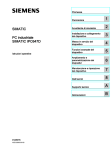
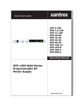
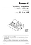
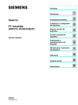
SIMATIC Rack PC 647B is an industrial PC in 19" rack format (2 HU) with high-performance
industrial functionality:
● Highly compact
● Extremely rugged
● Extensive product continuity
Figure 3-1
3.2
SIMATIC Rack PC 647B
Areas of application
The SIMATIC Rack PC 647B provides machine, systems and control cabinet engineering
companies with a high-performance and highly flexible 19" rack PC platform for machineoriented industrial applications:
● Automatic measurement and control systems for controlling process and machine data
● Visualization of production sequences and processes
● Computing and processing of images for QC
● Data acquisition and management
The SIMATIC Rack PC 647B has CE certification for use in the industrial sector as well as in
residential and commercial areas, and small businesses. In addition to the industrial
applications, it can also be used in building services automation or in facilities open to the
public.
SIMATIC Rack PC 647B
Operating Instructions, 04/2009, A5E02147327-02
11
Description
3.3 Highlights
3.3
Highlights
Highly compact:
● Compact housing design (2 HU)
● Flexibility for space-saving cabinet installation
Highly compatible with industrial standards:
● High operational vibration and shock resistance
● Wide operational temperature range
● High service friendliness
● Dust protection
● Distinct diagnostic features
High-performance industrial functionality:
● Integrated PROFIBUS DP / MPI interface (optional)
● PROFINET interface CP 1616 onboard (optional)
● PCI, PCIe x4, PCIe x16 slots
● High flexibility and expansibility of components
High investment security:
● High continuity of the components/design
● Guaranteed spare parts availability for at least 5 years
● Simple integration in PC-based automation
High system availability:
● SIMATIC PC DiagMonitor – PC diagnostics/message software by way of
OPC/SNMP/LAN
● SIMATIC PC/PG Image Creator – data imaging software
● RAID1 – redundant data storage to two hard disk volumes protects against data loss
12
SIMATIC Rack PC 647B
Operating Instructions, 04/2009, A5E02147327-02
Description
3.4 Function
3.4
Function
● Integrated programmable monitoring functions (program execution (watchdog), internal
housing temperature, fan speed)
● Enhanced diagnostic/messaging by way of Ethernet, E-mail, SMS, and for direct input in
SIMATIC software by way of OPC (optional using SIMATIC PC DiagMonitor):
– Operating hours counter
– Hard disk status
– System status (heartbeat)
– Automatic logging of all messages to a log file
– Option of remote monitoring of networked SIMATIC PCs
● RAID1 for automatic data mirroring on two hard disk volumes
SIMATIC Rack PC 647B
Operating Instructions, 04/2009, A5E02147327-02
13
Description
3.5 Features
3.5
Features
General features
Design
•
•
•
•
•
19" rack, 2 HU
Rugged panel-mount housing, all metal
Prepared for mounting telescopic rails
Horizontal installation is possible
Lockable front cover as access protection
Enclosure
•
Dust protection by means of overpressure ventilation using
bearing-seated front fan via filter
Enclosure cover fastened with a single screw
Front fan can be exchanged without tools
Card retainer for reliable operation of PC modules under
vibration and shock conditions
•
•
•
•
•
Front 2 x low profile removable rack
or
2 x 3.5" (in vibration damping drive bay)
1 x optical drive (slimline)
Slots for expansion cards
•
•
Alternative 2x PCI long or 1x PCI long, 1x PCIe x4 long
1 x PCI Express x16 long
Graphics
•
Onboard Intel® GMA950 graphics controller
2-D and 3-D engine integrated in chipset,
Dynamic Video Memory Technology
(uses up to 128 MB of RAM)
Max. 1280x1024 at 100 Hz / 32-bit color depth
Max. resolution:
2038x1536 at 75 Hz / 16-bit color depth
in PCIe x16 slot (optional)
PCIe x16 graphics card (dual head: 2 x VGA or 2 x DVI) 1)
128 MB RAM
Up to 2048 x 1536 pixels at 75 Hz / 32-bit color depth
Drive bays
•
•
Interfaces
14
PROFIBUS/MPI
12 Mbps (isolated potential, compatible to CP 5611); optional
PROFINET
10/100 Mbps (CP 1616 onboard), three RJ-45; optional
Ethernet
2x 10/100/1000 Mbps (two RJ-5)
Wake on LAN and Remote Boot supported
USB
2 x front panel, 4 x rear panel; (high current)
Serial
COM1 (V.24), COM2 (V.24) 9-pin
Parallel
LPT1
VGA
1x
Keyboard
PS/2
Mouse
PS/2
Audio
Microphone, Line out / Headset
SIMATIC Rack PC 647B
Operating Instructions, 04/2009, A5E02147327-02
Description
3.5 Features
General features
Power supply
1)
100 VAC to 240 VAC, wide range; with short-term power
failure backup in accordance with NAMUR: Max. 20 ms at
0.85 rated voltage
The modules should not occupy more than one slot
Monitoring functions
•
Overshoot/undershoot of permissible operating
temperature
Messages can be evaluated by the application program
Fan
•
•
Speed monitoring
Messages can be evaluated by the application program
Watchdog
•
•
•
•
Monitoring of program execution
Monitoring time can be parameterized in software
Restart can be parameterized in the event of a fault
Messages can be evaluated by the application program
Status LEDs
•
•
•
POWER (internal power supply unit, PC switched On)
HDD (access to hard disk drive)
ETHERNET 1, ETHERNET 2 (Ethernet status,
"heartbeat")
PROFIBUS/MPI (activation display of the PROFIBUS/MPI
interface), optional product feature
SF PROFINET (status display of the CP 1616 onboard
interface), optional product feature
WATCHDOG (Watchdog function/error display)
TEMP (temperature status)
FAN (speed monitoring)
HDD1, HDD2 Alarm RAID status message in conjunction
with SIMATIC monitoring software (only with RAID option)
Temperature
•
•
•
•
•
•
•
Basic variant
CPU motherboard
Motherboard without fieldbus
Bus module
3 slots (2 x PCI, 1 x PCIe x16)
Processor
Intel® Core™2 Duo T7400 (2.16 GHz, 667 MHz FSB,
4 MB Second Level Cache, EM64T, VT)
RAM expansion
512 MB SDRAM DDR2 667 (PC 5300)
Single Channel
2 x SO DIMM slots for max. 4 GB
Drives
Hard disks
80 GB SATA, 3.5", internal installation
Operating system
without
SIMATIC Rack PC 647B
Operating Instructions, 04/2009, A5E02147327-02
15
Description
3.5 Features
Optional accessories
Processor
•
•
Intel® Core™2 Duo T5500 (1.66 GHz, 667 MHz FSB,
2 MB Second Level Cache, EM64T)
Intel® Celeron® M 440 (1.86 GHz, 533 MHz FSB,
1 MB Second Level Cache)
RAM expansion
Up to 4 GB, dual-channel
PROFIBUS/MPI
12 Mbps (isolated potential, compatible to CP 5611)
PROFINET
10/100 Mbps (CP 1616 onboard, three RJ-45)
Bus module
3 slots (1x PCI, 1x PCIe x16, 1x PCIe x4)
Drives
CF drive
Slot for Compact Flash card
DVD burner slimline
Read:
DVD ROM: Single Layer 8x, Dual Layer 6x
DVD-R/+R: Single Layer 9x, Dual Layer 6x
DVD-RW/+RW 8x, DVD-RA; 5x
CD-ROM: CD-R 24x, CD-RW 24x
Write:
DVD+R 8x, DVD+RW 8x, DVD-R 8x, DVD-RW 6x,
DVD+R9 (DL) 6x, DVD-R DL 2x
CD-R 24x, CD-RW 24x
Hard disks 3.5" (SATA)
Installation in removable rack or vibration damped
• 80 GB
• 160 GB
• 2 x 160 GB;
• RAID1, 2 x 160 GB (mirror disks)
Graphics controllers
•
•
Operating system
Preinstalled / supplied on Restore DVD
• Windows XP Professional MUI*
• Windows Server 2003 MUI
• Windows Vista Ultimate
Add2 card (1x DVI-D)
PCIe x16 graphics card, dual head (2x VGA or 2x DVI-D)
*MUI: Multi language User Interface; 5 languages (German,
English, French, Spanish, Italian)
16
SIMATIC Rack PC 647B
Operating Instructions, 04/2009, A5E02147327-02
Description
3.5 Features
Languages that can be installed from operating system recovery CD / DVD
Language
Windows XP
Windows Server 2003
Windows Vista
German
X
X
X
English
X
X
X
French
X
X
X
Italian
X
X
X
Spanish
X
X
X
Japanese
X
X
Chinese (Hong Kong)
X
Chinese (simplified)
X
X
X
X
Chinese (Taiwan)
Korean
X
X
Languages that can be installed from the service pack CD / DVD
Language
Windows XP
Windows Vista
Russian
X
Korean
X
Chinese (simplified)
X
Optional expansions
SIMATIC PC
DiagMonitor SW
Software tool for monitoring local and remote SIMATIC
PCs:
• Watchdog
• Temperature
• Fan speed
• Hard disk monitoring (SMART, RAID status)
• System / Ethernet monitoring (Heartbeat)
SIMATIC PC
Image Creator SW
Software tool for saving data locally
SIMATIC Rack PC 647B
Operating Instructions, 04/2009, A5E02147327-02
17
Description
3.6 Setup
3.6
Setup
3.6.1
External design
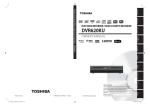
Front view of the device (example)
①
Front panel with vent openings
(filter mat and fan behind the front
panel). Check the filter mat
regularly for soiling and, if
appropriate, replace it.
②
Status displays
③
Reset button
④
On/off button
⑤
Lock
⑥
Option of installing:
• DVD burner drive (slimline)
• Hard disk removable rack
• Hard disk in vibration damping
drive bay
⑦
USB ports
⑧
Lockable front door for access
security. Keep the front door
closed during normal operation.
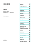
①
Fan / power supply unit
②
Equipotential bonding connection
③
Expansion slots
④
Connection elements
⑤
Power supply connector
Rear view of the device (example)
18
SIMATIC Rack PC 647B
Operating Instructions, 04/2009, A5E02147327-02
Description
3.6 Setup
3.6.2
Operator Controls
Control elements, On/Off and Reset buttons
①
On/off button
For switching the device on or off
②
Reset button
The reset button can be operated using a
pointed object or a paper clip, for example.
The button signal triggers a hardware
reset. The PC performs a restart (cold
start).
CAUTION
Data may be lost when the PC performs a hardware reset.
WARNING
The on/off button signal does not cut off power to the PC!
SIMATIC Rack PC 647B
Operating Instructions, 04/2009, A5E02147327-02
19
Description
3.6 Setup
3.6.3
Connecting elements
Layout of the interfaces on the rear of the device
Item
Designation
Description
①
DVI or
DMS59
DVI-D connector of the ADD2 card for digital monitors (optional) or
DMS59 connector for Dual Head graphics card (optional).
②
Audio (input)
Connectors for analog audio source, microphone, 3.5 mm phono jack
③
Audio (output)
Connector for active speakers or headset, 3.5 mm phono jack
④
VGA
Connection for VGA monitor
⑤
MOUSE
Connection for a PS/2 mouse
⑥
KEYBOARD
Connection for a PS/2 keyboard
⑦
LPT
Parallel interface, 25-pin
⑧
COM
Serial interface(V.24), 9-pin sub D plug
⑨
ETHERNET 1, 2 *
2 x RJ-45 connectors, Ethernet 10/100/1000 Mbps
⑩
USB
USB device connectors. USB ports 1 to 4
⑪
Blanking plate
Optional product variant
PROFIBUS/MPI
PROFIBUS interface (RS 485, electrically isolated), 9-pin D-sub socket (optional
product characteristic)
PROFINET
CP 1616 onboard interface, three RJ-45 jacks (optional product version)
*
20
For unique labeling, the LAN interfaces are numbered on the enclosure. The operating system numbering may
deviate from this.
SIMATIC Rack PC 647B
Operating Instructions, 04/2009, A5E02147327-02
Description
3.6 Setup
Item
Designation
Description
⑫
VGA
(via the graphics card)
VGA connection (adapter plugged in)
⑬
DVI-I
(via the graphics card)
DVI-I connection
⑭
Dual-head adapter (via
the graphics card)
DMS59 connector on dual-head graphics card (optional)
Power supply
Position of the IEC connector
Description
IEC connector for the AC power supply to the
device. The permitted power range is 100 VAC to
240 VAC.
SIMATIC Rack PC 647B
Operating Instructions, 04/2009, A5E02147327-02
21
Description
3.6 Setup
3.6.4
Status displays
Front status displays
22
Display
Meaning
LEDs
Description
POWER
PC status display
OFF
isolated from mains
YELLOW
Standby (hibernating)
GREEN
PC in operation
HDD
Display for hard disk
access
OFF
no access
GREEN
Access
ETHERNET 1 *
ETHERNET status
display
OFF
•
•
GREEN
Data traffic
ETHERNET 2 *
ETHERNET status
display
OFF
•
•
GREEN
Data traffic
PROFIBUS/MPI
(optional)
Display of the
communication status to
S7 or PROFIBUS
OFF
•
•
GREEN
Data traffic
No connection
No data traffic
No connection
No data traffic
No connection
No data traffic
SIMATIC Rack PC 647B
Operating Instructions, 04/2009, A5E02147327-02
Description
3.6 Setup
Front status displays
SF PROFINET
(optional)
Status display for
CP 1616 onboard
OFF
•
•
•
•
•
•
Flashes slowly
•
•
•
Link status error
IO controller: IO device cannot
be addressed
IO controller: Duplicate
IP address
Flashes rapidly
Exception error: diagnostics via
Web or SNMP is no longer
possible
AN
•
•
WATCHDOG
CP not available
CP disabled
No error, communication
established
Charging in progress
CP 1616 driver not installed
CP in NDIS mode
Diagnostics information
available
No communication
established.
WATCHDOG status
display
OFF
WATCHDOG not activated
GREEN
WATCHDOG monitoring enabled
RED
Monitoring time elapsed
TEMP
Internal temperature
monitoring
OFF
Internal temperature OK
RED
Internal temperature critical
FAN
Fan status (only with
active SOM or
DiagMonitor software)
OFF
Fan speed OK
RED
Fan speed too low
Hard disk alarm in
conjunction with RAID
and monitoring software
OFF
RAID is OK
One RED
HDD1 or HDD2 not OK
Both RED
RAID not OK
(for information on locating the
faulty HDD, refer to the RAID
system (Page 50) section)
Both flash
RAID is synchronized
Error in early BIOS Post
All lit
CPU startup failure
Error in early POST
HDD1 ALARM
HDD2 ALARM
All displays are lit
*
For unique labeling, the LAN interfaces are numbered on the enclosure. The operating system
numbering may deviate from this.
SIMATIC Rack PC 647B
Operating Instructions, 04/2009, A5E02147327-02
23
Description
3.6 Setup
Rear status displays
/('
/('
Display
Meaning
LED
Description
Ethernet LAN 1, 2 *
Green LED
Link status display
OFF
•
•
•
GREEN
Active cable connected
Yellow LED
Activity status display
OFF
•
•
•
•
YELLOW
Data transfer active
PROFINET LAN X1, Green LED
P1, P2, P3 *
Link status display of
CP 1616 channel
OFF
•
•
•
GREEN
Active cable connected
OFF
•
•
•
•
YELLOW
Data transfer active
Yellow LED
Activity status display
of CP 1616 channel
*
No cable connected
Cable disabled
Interface disabled
No cable connected
Cable disabled
Interface disabled
No activity
No cable connected
Cable disabled
Interface disabled
No cable connected
Cable disabled
Interface disabled
No activity
For unique labeling, the LAN and PROFINET interfaces are numbered on the housing. The
numbering by the operating system may deviate from this.
Virtual status displays
The two "virtual" CP 1616 LEDs are only visible in the SIMATIC software and can be read via SNMP.
PROFINET
24
Virtual LEDs
RUN
CP is active
STOP
CP is in the stop state
Flashes
The states "flashes slowly" or
"flashes rapidly" do not exist.
SIMATIC Rack PC 647B
Operating Instructions, 04/2009, A5E02147327-02
Application planning
4.1
4
Transport
Despite the device's rugged design, its internal components are sensitive to severe
vibrations or shock. You must therefore protect the PC from severe mechanical stress when
transporting it.
You should always use the original packaging for shipping and transporting the device.
CAUTION
Risk of damage to the device!
When transporting the PC in cold weather, it may be submitted to extreme variations in
temperature. In this situation, ensure that no moisture (condensation) develops on or inside
the device.
If condensation has developed on the device, wait at least 12 hours before you switch it on.
SIMATIC Rack PC 647B
Operating Instructions, 04/2009, A5E02147327-02
25
Application planning
4.2 Unpacking and checking the delivery unit
4.2
Unpacking and checking the delivery unit
Unpacking the device
Note the following points when you unpack the unit
● It is advisable not to dispose of the original packing material. Keep it in case you have to
transport the unit again.
● Please keep the documentation in a safe place. It is required for initial commissioning and
is part of the device.
● Check the delivery unit for any visible transport damage.
● Verify that the shipment contains the complete unit and your separately ordered
accessories. Please inform your local dealer of any disagreements or transport damage.
● Please inform Siemens AG by means of the enclosed SIMATIC IPC/PG quality control
report form.
Noting down the device identification data
The device can be clearly identified with the help of this identification data in case of repairs
or theft.
Enter the following data in the table below:
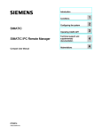
● Serial number: The serial number (S VP) is located on the rating plate inside the front
door.
Figure 4-1
Rating plate
● Order number of the device
26
SIMATIC Rack PC 647B
Operating Instructions, 04/2009, A5E02147327-02
Application planning
4.2 Unpacking and checking the delivery unit
● Ethernet address: The Ethernet address of the device is available in BIOS Setup (F2
function key) , at Info > (F1 function key) > LAN Address.
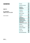
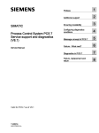
● Microsoft Windows "Product Key" on the "Certificate of Authenticity" (COA). The COA
label is attached to the inside of the front door.
You may need the Product Key in case you reinstall the operating system.
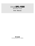
Figure 4-2
COA label
Serial number
S VP ...
Order no.
6AG4112-0 ...
Microsoft Windows Product Key
Ethernet 1 address
Ethernet 2 address
CP 1616 onboard layer 2
Device equipment
The device equipment is listed on the inner side of the front door.
SIMATIC Rack PC 647B
Operating Instructions, 04/2009, A5E02147327-02
27
Application planning
4.3 Ambient and environmental conditions
4.3
Ambient and environmental conditions
When you plan your project, you should make allowances for:
● Observe the climatic and mechanical environmental conditions in the technical data in
your operating instructions.
● Avoid extreme ambient conditions as far as possible. Protect your device against dust,
moisture and heat.
● The device is designed for use in normal industrial environments to IEC 60721-3-3
(pollutant class 3C2 for chemical influence, 3S2 for sand and dust.) SIMATIC Rack PCs
may not be operated in severe environments which are subject to caustic vapors or
gases without taking additional protective measures (such as the provision of clean air.)
● Do not expose the device to direct sunlight.
● Install the device in such a way that it poses no danger, for example, by falling over.
● The device conforms to protection class IP41 at the front panel. Ensure that the
installation opening for the device is splash-proof in areas which may be subject to splash
water.
● Always maintain a minimum clearance of 50 mm to the area of the ventilation slots in
order to ensure adequate ventilation of the PC.
● Do not cover the ventilation slots of the enclosure.
● The device meets requirements for fire protection housings to EN 60950-1 and can be
installed without additional fire protection enclosure.
● The connected or built-in peripherals should not introduce a counter emf in excess of
0.5 V into the device.
WARNING
Failure to comply with these requirements for system installation shall render approvals
to UL 60950-1, EN 60950-1 void and leads to the risk of overheating and injury!
4.4
Access protection
The access protection of the rack PC is only enabled if the front door is locked.
28
SIMATIC Rack PC 647B
Operating Instructions, 04/2009, A5E02147327-02
5
Installing
5.1
Installing the device
Optional installation locations
The device can be installed horizontally in control desks, in switch cabinets and in 19-inch
rack systems.
Optional mounting methods
Options of mounting the device
● Mounting on cabinet brackets
● Mounting on device bases
● Mounting on telescopic rails
When telescopic rails are used for mounting, the device can be withdrawn fully from the
cabinet or rack.
For more detailed information on telescopic rails, refer to the sections Technical data of
the telescopic rails (Page 148) and Dimensional drawing for the use of telescopic rails
(Page 150).
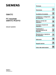
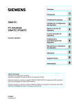
Figure 5-1
Position of the mounting holes ①
CAUTION
The mounting screws of the telescopic rails may not protrude more than 5 mm into the
enclosure.
CAUTION
Risk of injury!
It is not permitted to install the device only on the 19-inch brackets of the front panel.
SIMATIC Rack PC 647B
Operating Instructions, 04/2009, A5E02147327-02
29
Installing
5.1 Installing the device
30
SIMATIC Rack PC 647B
Operating Instructions, 04/2009, A5E02147327-02
Connecting
6.1
6
Connecting peripherals
Note before connecting
NOTICE
Connect only peripherals approved for industrial applications according to EN 61000-6-2.
Note
Hot-plug I/O modules (USB) may be connected while the PC is in operation.
CAUTION
I/O devices that are incapable of hot-plugging may only be connected after the device has
been disconnected from the power supply.
CAUTION
Strictly adhere to the specifications in the I/O manuals.
NOTICE
The connected or built-in peripherals should not introduce a counter emf into the device.
A counter emf greater than 0.5 V to ground on the + 3.3 VDC / + 5 VDC / + 12 VDC power
rail due to a connected or integrated component can prevent normal operation or even
destroy the computer.
When measuring the counter emf, remember the following:
• The computer in question must be turned off and the power supply connector should be
plugged in.
• During the measurement, all cables from the plant to the computer should be
connected.
• All other components in the plant must be active.
SIMATIC Rack PC 647B
Operating Instructions, 04/2009, A5E02147327-02
31
Connecting
6.2 Connecting the device to power
6.2
Connecting the device to power
Note before connecting
Note
The wide-range power supply module is designed for operation on 100 VAC to 240 VAC
mains. The setting of the voltage range takes place automatically.
WARNING
Do not connect or disconnect power and data cables during thunderstorms.
WARNING
The device may only be operated on grounded power supply networks (TN systems to
VDE 0100, part 300, or IEC 60364-3).
Operation on ungrounded or impedance-grounded power networks (IT networks) is
prohibited.
WARNING
The permitted nominal voltage of the device must conform with local mains voltage.
CAUTION
The mains connector must be disconnected to fully isolate the device from mains. Ensure
easy access to this area.
A master mains disconnect switch must be installed if the device is mounted in a switch
cabinet. Always ensure free and easy access to the power inlet on the device or that the
safety power outlet of the building installation is freely accessible and located close to the
device.
Note
The power supply contains a PFC (Power Factor Correction) circuit to conform with the EMC
directive.
Uninterruptible AC power systems (UPSs) must supply a sinusoidal output voltage in the
normal and buffered mode when used with SIMATIC PCs with a PFC circuit.
UPS characteristics are described and classified in the standards EN 50091-3 and IEC
62040-3. Devices with sinusoidal output voltage in the normal and buffered mode are
identified with the classification "VFI-SS-...." or "VI-SS-....".
32
SIMATIC Rack PC 647B
Operating Instructions, 04/2009, A5E02147327-02
Connecting
6.2 Connecting the device to power
Localized information
Outside of the USA and Canada, operation on a 230 V power supply:
This device is equipped with a safety-tested power cord which may only be connected to a
grounded shockproof power outlet. If you choose not to use this cable, you must use a
flexible cable of the following type: Min. 18 AWG conductor cross-section and 15-A / 250-V
shock-proof connector. The cable set must be compliant with safety regulations and
stipulated IDs of the country where the system is to be installed.
For the USA and Canada:
For the United States and Canada, a CSA or UL-listed power cord must be used.
The connector must be compliant with NEMA 5-15.
120 V AC power supply
To be used is a flexible power cord approved to UL and with CSA label, and which has the
following features: Type SJT with three leads, min. 18 AWG conductor cross-section, max.
length 4.5 m, parallel grounding plug 15 A, min. 125 V.
240 VAC power supply
Use a flexible power cord which is approved to UL and CSA, and which has the following
features: Type SJT with three conductors, min. 18 AWG conductor cross-section, max.
length 4.5 m, and tandem grounded connector 15 A, min. 250 V.
Connecting
Steps for connecting the device to mains
1. Connect the power plug.
2. Connect the power cable to the socket and
turn on the power switch (if present)
The yellow power LED (standby) on the front
panel of the PC lights up.
SIMATIC Rack PC 647B
Operating Instructions, 04/2009, A5E02147327-02
33
Connecting
6.2 Connecting the device to power
Secure the power plug
You can secure the power plug in order to avoid unintentional disconnection of the power
cord.
Steps for securing the power plug
1. Loosen the screw ② on the power supply
unit.
2. Screw the power plug locking mechanism ①
to the power supply unit with this screw.
WARNING
If the power plug is secured with a clamp, the power outlet must be freely accessible to
allow the device to be easily removed from the mains.
34
SIMATIC Rack PC 647B
Operating Instructions, 04/2009, A5E02147327-02
Connecting
6.3 Equipotential bonding
6.3
Equipotential bonding
A low-impedance ground connection improves the discharge of interference generated by
external power cables, signal cables or cables for I/O modules to ground.
Equipotential bonding terminal
The equipotential bonding terminal ① on the device
(large surface, large-area contact) must be
connected with the central grounding busbar of the
cabinet or plant in which the PC is to be installed.
The minimum conductor cross-section may not be
less than 5 mm2.
SIMATIC Rack PC 647B
Operating Instructions, 04/2009, A5E02147327-02
35
Connecting
6.4 Connecting PROFINET strain relief
6.4
Connecting PROFINET strain relief
The PROFINET strain relief provided in the package is used to prevent accidental loosening
of the cable from the device. A cable tie (not included in the package) is needed for each
interface.
To fix the PROFINET strain relief, you will need a TORX T10 screwdriver.
Steps for connecting the PROFINET strain relief
1. Remove the PROFINET interface plate.
36
SIMATIC Rack PC 647B
Operating Instructions, 04/2009, A5E02147327-02
Connecting
6.4 Connecting PROFINET strain relief
Steps for connecting the PROFINET strain relief
2. Attach the PROFINET strain relief.
3. Attach the cable using the cable tie.
SIMATIC Rack PC 647B
Operating Instructions, 04/2009, A5E02147327-02
37
Connecting
6.4 Connecting PROFINET strain relief
38
SIMATIC Rack PC 647B
Operating Instructions, 04/2009, A5E02147327-02
Commissioning
7.1
7
Requirements for commissioning
● Before you switch on the device, you should verify that all peripheral devices such the
keyboard, mouse, monitor and the power supply are connected.
● The operating system of your device is preinstalled on the hard disk.
CAUTION
Risk of damage to the device!
Make sufficient allowances for the device to acquire room temperature before you put it
into use. If condensation has developed on the device wait at least 12 hours before you
switch it on.
SIMATIC Rack PC 647B
Operating Instructions, 04/2009, A5E02147327-02
39
Commissioning
7.2 Initial Commissioning - Initial Startup
7.2
Initial Commissioning - Initial Startup
The Rack PC operating system is automatically set up the first time you switch on the
device. Procedure:
1. Press the on/off button. The green power LED lights up. The PC performs a POST.
During the self-test, this message appears:
Press <F2> to enter SETUP
2. Wait until this message is cleared, then follow the instructions on the screen.
3. Type in the Product Key as required. You find this key on the "Certificate of
Authentication", in the "Product Key" line.
NOTICE
The PC may not be switched off when you run setup.
Do not change the default BIOS settings, otherwise the operating system setup may
become corrupted.
4. Automatic restart
After you have entered all necessary information and after the operating system
setup is completed, the PC is automatically restarted and displays the user interface of the
relevant operating system.
From now on, after you switch on the PC, the user interface of the operating system is
automatically opened when the startup routine is completed.
Switching off the device
Note
On a Windows platform, always shut down the PC by clicking Start > Close.
Press the on/off button behind the front panel door. The green power LED is switched off.
Disconnect the mains connector to isolate the device from mains.
40
SIMATIC Rack PC 647B
Operating Instructions, 04/2009, A5E02147327-02
Commissioning
7.3 Windows XP, Vista Security Center
7.3
Windows XP, Vista Security Center
Warning from the Windows Security Center
A warning from the Windows Security Center appears the first time you switch on your
device. The Security Center checks the status of the device with regard to the three
important security aspects listed below. If a problem is detected (an outdated antivirus
program, for example), the Security Center issues a warning and makes recommendations
on how you can better protect the device.
● Firewall: The Windows Firewall adds protection to the device by blocking network or
Internet access to the device by unauthorized users. Windows checks if the device is
protected by a software firewall.
The firewall is enabled by default in the factory state.
● Antivirus software: Antivirus programs add protection to the device by searching for and
eliminating viruses and other security threats. Windows checks if a full-range, up-to-date
antivirus program is running on the device.
No antivirus software is installed in the factory state.
● Automatic updates: Using the Automatic Update feature allows Windows to regularly
search for the latest critical updates for the device and to install them automatically. This
feature is disabled in the factory state.
● Real-time protection (Vista only): Windows Defender displays warnings if spyware or
possibly unwanted software is installed or executed on the computer. You will also
receive a warning if programs attempt to modify important Windows settings.
Configure the Security Center according to your requirements.
SIMATIC Rack PC 647B
Operating Instructions, 04/2009, A5E02147327-02
41
Commissioning
7.4 Notes on operation
7.4
Notes on operation
7.4.1
Compact Flash card (optional)
NOTICE
We highly recommend that use use approved SIMATIC Compact Flash cards. Siemens
disclaims any liability for impairment of functions caused by the use of third-party cards.
Installation
It is possible to operate the optional CompactFlash card adapter with a CompactFlash card
as a flash drive.
Features
The flash drive with Contract card acts just like a standard IDE hard disk. No special driver
software is required to operate the Flash drive.
Although the Flash drive reacts like a hard disk superficially, there are restrictions due to the
limited number of write cycles on Flash memory. The service life of a Compact Flash card
depends on the number of write access to the medium - read accesses have no effect.
To maximize the service life of Compact Flash cards, take care that the writing to the cards
is kept to a minimum.
For example, you can do this by ensuring that:
● Swap files of the operating system and application are not located on the Compact Flash
card.
● Cyclic writing is avoided.
Operating systems such as MS-DOS and Windows XP Embedded allow this, for example.
The Enhanced Write Filter (EWF) can be used with XP Embedded, for example. This
minimized the number of write accesses to the Flash drive or avoids it entirely.
42
SIMATIC Rack PC 647B
Operating Instructions, 04/2009, A5E02147327-02
Commissioning
7.4 Notes on operation
Flash drive functions
A Flash drive or a Compact Flash card consists of Flash memory chips.
An intelligent controller integrated in the flash drive manages the flash memory. This
optimizes the use of the Flash memory to achieve a maximum service life.
The service life of a Flash drive depends in part on the following factors:
● Type of file
Executable files (*.EXE) are usually only written once and stays at the same storage
location.
● The number of writes within a given time (the less the better)
Comparison of Flash drive and hard disk drive service life
Examples of the service life for a Flash drive:
With a "Data logger function", a 4 KB file is written to a 1 GB Compact Flash card every
5 seconds. The cluster size is 4 KB in this case. Due to the file segmentation, the file is
always written to another location on the Compact Flash card.
With this example, the Compact Flash card has a theoretical service of 79.3 years.
Example of the service life for a hard disk drive
The service life of a hard disk drive depends on the following factors:
● Temperature (operating & storage / transport)
● Shock (operating & storage / transport)
● Vibration (operating & storage / transport)
● Humidity (operating & storage / transport)
● Voltage supply
● Power on hours (POH)
● Duty cycle (% workload, i.e. write/read/positioning)
The service life for a hard disk is between 2.5 and 5 years, depending on the factors listed
above.
Booting from the Flash drive
To be able to boot from the flash drive, you first need to install an operating system and set
the boot priority. You will find the procedure for installing an operating system described in
the section Installing Microsoft Windows operating systems (Page 123). How to change the
boot priority in the BIOS setup is described in the section Boot menu (Page 210).
SIMATIC Rack PC 647B
Operating Instructions, 04/2009, A5E02147327-02
43
Commissioning
7.4 Notes on operation
7.4.2
DVD burner
The DVD burner drive is an optional feature. Recording methods supported by the disk drive:
Disc-at-once, Track-at-once, Session-at-once, Packet writing. You can write to CD-R, CDRW, DVD+R, DVD-R, DVD-RW, DVD+RW, DVD-RAM and dual-layer media.
Burner software
In order to utilize full functionality of the DVD burner you need to install additional software
(burning software). This software is included on the CD supplied with the device. Insert the
CD in the drive, run setup and follow the instructions on the screen.
NOTICE
When first starting the burner software, no data carriers should be inserted in the drive. This
is because data carriers with errors can interrupt the automatic hard drive recognition. This
makes it impossible to correctly display the possible burner functions.
Notes on burning optical data carriers
CAUTION
Danger of data errors when burning data carriers!
Burning is permissible only in an undisturbed environment, i.e. shock and vibration stress
must be avoided. Because of heavy fluctuation in the quality of CD-Rs, data may be
corrupted in a burning session, even if no error message is initially displayed. The written
data can only be verified by comparing these with the source. To be on the safe side, data
should be verified after every burning session.
44
SIMATIC Rack PC 647B
Operating Instructions, 04/2009, A5E02147327-02
Commissioning
7.4 Notes on operation
7.4.3
Removable hard disks
The removable racks support hot plugging in a RAID1 system. If, however, you have
configured a non-RAID system, you will need to turn the device off before exchanging the
rack.
Notes on operation
Note
Always replace the faulty drive with a new drive of the same type and capacity.
NOTICE
Always lock the hard disk cartridge in the removable rack to ensure reliable operation of the
device.
CAUTION
Hard drives may only be replaced in a removable rack if the hard drive is inactive and the
HDD activity display of the device is off. Check the ESD Guidelines (Page 231).
Identifying a defective hard drive
Note
The table and information below apply only to the delivery state of the device, that is if no
changes or expansions were made.
Power LED ①
power applied
HDD activity display ②
SIMATIC Rack PC 647B
Operating Instructions, 04/2009, A5E02147327-02
You should also check the HDD access
display ⑦, HDD 1 ALARM ⑥ or HDD 2
ALARM ⑤.
See also the section Status displays
(Page 22) .
45
Commissioning
7.4 Notes on operation
The table below shows the assignment of the exchangeable rack positions in the device to
the RAID system reports:
Assigned LED 1)
RAID
BIOS
RAID software
SATA
interface
Installation location
Enclosure
labeling
HDD1 ALARM
Port 0
Device Port 0
SATA0
③ Removable rack
1
HDD2 ALARM
Port 2
Device Port 2
SATA2
④ Removable rack
2
If the SIMATIC monitoring software is installed, the status LED ⑤ or ⑥ on the front panel
is lit if the hard disk has failed.
1)
Replacing a hard disk
Steps for replacing the hard disk
1.
Check which hard disk the RAID
controller has reported being faulty
(hard disk on channel 1 or 2).
2.
Turn the locking switch ① to the
"OPEN" position.
3.
46
Press on the marking or press the
release in the direction of the arrow,
so that the lever on the hard disk
cartridge comes out.
SIMATIC Rack PC 647B
Operating Instructions, 04/2009, A5E02147327-02
Commissioning
7.4 Notes on operation
Steps for replacing the hard disk
4.
Pull the lever out until you feel the
hard disk cartridge release and pull it
out completely.
5.
Loosen the four screws on the base
of the cartridge.
6.
Remove the hard disk from the
cartridge.
7.
Always replace the defective disk with
a new one of the same type and
capacity. Take care not to touch the
contacts.
8.
Secure the hard disk with the four
screws on the base of the cartridge.
Only use the original screws.
SIMATIC Rack PC 647B
Operating Instructions, 04/2009, A5E02147327-02
47
Commissioning
7.4 Notes on operation
Steps for replacing the hard disk
9.
Close the lever ① of the hard disk
cartridge again.
10.
Return the locking switch ① to the
"LOCK" position. You can hear
clearly when the removable rack is
locks into position.
Information about the recovery of the RAID system is available in the section RAID system
(Page 50).
48
SIMATIC Rack PC 647B
Operating Instructions, 04/2009, A5E02147327-02
Commissioning
7.4 Notes on operation
7.4.4
2HDD system (optional)
When the device ships, the second hard disk is connected to SATA port 2. This hard disk
drive is not set up. This gives you the option of backing up your data to this hard disk. For
information on hard disk capacities, refer to your order documentation.
Booting from the slave hard disk
In order to allow booting from the second hard disk, you need to configure it as the primary
boot device. Make the following settings in your BIOS Setup:
Select Boot > Hard Drive > <Disk name> e.g. STxxxxxxxxx- SATA2, then press the "+" key
to move it up in the boot order.
NOTICE
The drive letters for the partitions on both drives are assigned by the operating system
used. You can change these in the Control Panel as required.
SIMATIC Rack PC 647B
Operating Instructions, 04/2009, A5E02147327-02
49
Commissioning
7.4 Notes on operation
7.4.5
RAID system
This is a RAID1 system configuration (mirroring with two hard disks). This configuration
enhances system availability as the system is able to continue operation if a hard drive fails,
or if there is a cable problem at a channel.
Note
You can find information regarding Intel RAID controllers in the RAID documentation on the
included "Documentation and Drivers" CD in the Drivers\RAID\Intel directory.
Intel(R) Matrix Storage Manager option ROM v5.6.2.1002 ICH7R wRAID5
Copyright(C) 2003-06 Intel Corporation.
All Rights Reserved.
RAID Volumes:
ID
Name
0
Volume0
Level
RAID1(Mirror)
Physical Disks:
Port Drive Model
0
ST3160815AS
2
ST3160815AS
Serial #
5RA01YJT
5RA01YHY
Press
Status
Rebuild
Bootable
Yes
Size
149.1GB
149.1GB
Type/Status(Vol ID)
Member Disk(0)
Member Disk(0)
50
Size
149.1GB
<CTRL-I> to enter Configuration Utility...
Figure 7-1
Strip
N/A
Example
SIMATIC Rack PC 647B
Operating Instructions, 04/2009, A5E02147327-02
Commissioning
7.4 Notes on operation
RAID system management functions
The pre-installed RAID system software offers enhanced functionality for RAID system
operation and management. Start the SW by selecting the "Start > Programs > Intel Matrix
Storage Manager command.
Figure 7-2
Example
The "View -> Advanced Mode" command returns details of the RAID volumes.
The command "View -> System Report" can be used to create a report with details of the
RAID volumes.
NOTICE
The RAID status entries are returned by default in the Windows event view and in the log
file of the program.
A hard drive can be synchronized at operating system level if a fault is detected. It may take
up to several hours to synchronize a new hard disk in the background, depending on the its
size and on system load.
The redundant system state RAID Level 1 is only recovered if synchronization has been
successfully completed.
SIMATIC Rack PC 647B
Operating Instructions, 04/2009, A5E02147327-02
51
Commissioning
7.4 Notes on operation
Comments about faults
NOTICE
Input delay
System load may briefly increase due to synchronization when a hard disk has failed,
depending on processor load and current hard disk activity.
Execution of keyboard and touch screen commands may be briefly delayed in extreme
situations.
Before you replace the defective hard disk, create a backup copy of the system.
Replacing a faulty drive in a RAID array
Replace faulty RAID drives with a new drive in order to recover secure RAID1 state. The
RAID software reports the faulty drive and returns details of the operable hard drive.
The functioning hard drive is indicated in BIOS by its port number, or by the RAID software
by its device port number.
Figure 7-3
52
Example
SIMATIC Rack PC 647B
Operating Instructions, 04/2009, A5E02147327-02
Commissioning
7.4 Notes on operation
Note
The table and information below apply only to the delivery state of the device, that is no
changes or expansions were made.
The functioning drive can be located using the following pictures and tables.
Figure 7-4
Drives in the exchangeable rack
Assigned LED 1
RAID
BIOS
RAID software
SATA
interface
Installation location
Enclosure
labeling
HDD1 ALARM ⑥
Port 0
Device Port 0
SATA0
Removable rack ①
1
HDD2 ALARM ⑤
Port 2
Device Port 2
SATA2
Removable rack ②
2
Figure 7-5
Drives in vibration damping drive bay
Assigned LED 1
RAID
BIOS
RAID software SATA
interface
Installation location
Enclosure
labeling
HDD1 ALARM
Port 0
Device Port 0
SATA0
Drive bay ④
Drive ①
1
HDD2 ALARM
Port 2
Device Port 2
SATA2
Drive bay ④
Drive ②
2
If the SIMATIC monitoring software is installed, the LED ⑤ or ⑥ of the status displays on
the front panel is lit if the hard disk is defective.
1)
Note
Always replace the faulty drive with a new one of the same type and capacity
SIMATIC Rack PC 647B
Operating Instructions, 04/2009, A5E02147327-02
53
Commissioning
7.4 Notes on operation
NOTICE
Drives in removable racks can be hot-plugged without shutting down the device.
Devices without exchangeable rack may only be replaced in shutdown state.
The new HDD can be integrated into the RAID system at operating system level by means
of the RAID software. Synchronization may take several hours, depending on system load.
Both HDD alarm displays of the front panel flash during synchronization. This is not
possible at BIOS level.
Points to note if the hard disk is replaced when the computer is turned off
Only a hard disk that was active and functioning correctly when you booted can later be
included in the RAID array.
To be able to boot from the RAID system, you must place this first in the list of bootable
sources in the BIOS "Boot" setup menu. Otherwise the system will boot from the hard disk
you have just installed and the message "Operating system not found" will be displayed.
54
SIMATIC Rack PC 647B
Operating Instructions, 04/2009, A5E02147327-02
Commissioning
7.4 Notes on operation
Integrating a new hard drive
Select the "Rescan for Plug and Play Devices" command to find and indicate the new HDD.
You can also choose to reboot the device. In this case, the RAID software automatically
integrates the new HDD and synchronizes the RAID system.
Figure 7-6
Example
If you have shut down and restarted the system without installing a functioning new hard
disk, "unused" will be displayed for the corresponding SATA port. In this case, you will need
to shut down the system again and boot with the functioning hard disk. The new hard disk is
then assigned to a SATA port and can be included in the RAID array.
SIMATIC Rack PC 647B
Operating Instructions, 04/2009, A5E02147327-02
55
Commissioning
7.4 Notes on operation
The "Rebuild to this Hard drive" command initiates synchronization of the RAID1 system.
Figure 7-7
56
Example
SIMATIC Rack PC 647B
Operating Instructions, 04/2009, A5E02147327-02
Commissioning
7.4 Notes on operation
Notes on RAID configuration with installed SIMATIC PC DiagMonitor software
When creating a RAID-system where SIMATIC PC DiagMonitor software is being used, the
Intel Matrix Storage Console may abort the process with the following error message:
Solution:
Before performing a RAID commissioning, the SIMATIC PC DiagMonitor should be
deactivated. Subsequently, it can be reactivated.
Measures:
If the DiagMonitor Management Station is in operation on your device:
● Close all applications, including the Management Station.
● Afterwards, stop the DiagMonitor SNMP Agent (SOL Agent). In order to do so, select
Start > Run and enter cmd in the Open field.
● Then enter Net stop snmp and confirm with the Enter key.
If your device is remotely monitored with SIMATIC PC DiagMonitor:
In this case you need only stop the DiagMonitor SNMP Agent (SOL Agent).
SIMATIC Rack PC 647B
Operating Instructions, 04/2009, A5E02147327-02
57
Commissioning
7.4 Notes on operation
● In order to do so, select Start > Run and enter cmd in the Open field.
● Then enter Net stop snmp and confirm with the Enter key.
NOTICE
If you do not adhere to the procedure described above, a correct RAID configuration
cannot be guaranteed.
58
SIMATIC Rack PC 647B
Operating Instructions, 04/2009, A5E02147327-02
Integration into an Automation System
8.1
8
Integration
Options of integration in existing or planned system environments/networks:
Ethernet
Wake on LAN and Remote Boot are supported.
The integrated Ethernet interfaces (10/100/1000 Mbps) can also be used for communication
and data exchange with programmable controllers such as SIMATIC S7.
This functionality requires the "SOFTNET S7" software package.
PROFIBUS/MPI
The optional electrically isolated PROFIBUS interface (12 Mbps) can be used to interconnect
distributed field devices or for coupling to SIMATIC S7.
The "SOFTNET for PROFIBUS" software package is required for coupling to S7 automation
systems.
PROFINET
CP 1616 onboard allows you to connect industrial PCs to Industrial Ethernet. Only one CP
1616 module can be installed in a PG/PC. You will find detailed information in the next
section PROFINET (Page 61) or in the detailed descriptions > CP 1616 onboard
communications processor (Page 218).
Device driver CP 16xx.sys
The device driver allows you to use the Windows network protocol for the optionally available
"CP 1616 onboard" Ethernet PROFINET controller on SIMATIC PCs. In Windows, the
PROFINET interface will act like a 100 Mbps Ethernet interface with a MAC address when
you use this driver. The three RJ-45 jacks are connected to each other via switch.
The drivers and documentation can be found in the user manual on the supplied
Documentation and Drivers CD.
PROFINET IO application
You can create, run or configure PROFINET IO applications with the Development Kit DK16xx PN IO. It must be installed in addition to the CP 16xx.sys device driver. This kit and the
documentation is available free of charge at the following Internet address: DK-16xx PN IO
development kit
(http://www.automation.siemens.com/net/html_00/produkte/040_cp_1616_devlopkit.htm)
SIMATIC Rack PC 647B
Operating Instructions, 04/2009, A5E02147327-02
59
Integration into an Automation System
8.1 Integration
SIMATIC NET
You can create, operate and configure SIMATIC installations using this software package.
You will find this information on the SIMATIC NET Manual Collection CD. The software
package and the documentation are not parts of the development package.
Additional information
You will find additional information in the catalog and the Siemens online ordering system
Industrial Automation and Drive Technologies (http://mall.automation.siemens.com)
.
60
SIMATIC Rack PC 647B
Operating Instructions, 04/2009, A5E02147327-02
Integration into an Automation System
8.2 PROFINET
8.2
PROFINET
CP 1616 onboard
The basic characteristics of the PCS 1616 onboard are:
● Optimized for PROFINET IO
● With Ethernet realtime ASIC ERTEC 400
● Three RJ-45 jacks for connecting terminal devices or addition network components
● Integrated 3-port real-time switch
● Automatic hardware detection
CAUTION
Only one CP 1616 can be installed in a PG/PC. If you want to use an additional CP
1616 module, the "CP 1616 onboard" option must be disabled in the BIOS Setup.
Additional documentation on PROFINET
Get an overview of the information available on the topic of PROFINET.
Document designation
What is contained in this document?
This documentation is not included in the product package:
Getting Started
PROFINET IO Getting Started: Manual
Collection
The documents use concrete examples to provide
step-by-step instructions on how to commission a fully
functional application.
Manual
PROFINET System Description
This gives you the basic knowledge about the
PROFINET IO topics:
Network components, data exchange and
communication, PROFINET IO, component-based
automation, application example of PROFINET IO and
component-based automation.
Manual
From PROFIBUS DP to PROFINET IO
Read this document if you want to convert an installed
PROFIBUS system to a PROFINET system.
Readme file for CP 1616/CP 1604 and DK16xx PN IO
This provides the latest information about the
SIMATIC NET products CP 1616/CP 1604, CP 1616
onboard, the developer kit.
Configuration Manual
Commissioning PC Stations
This provides you will all the information necessary for
commissioning and configuring a PC as a PROFINET
IO controller or IO device.
Manual
SIMATIC NET Industrial Communication
with PG/PC: Volume 1 - Basics
This manual introduces you to industrial
communication and explains the available
communication protocols. It also describes the OPC
interface as an alternative to the IO-based user
programming interface.
SIMATIC NET Industrial Communication
with PG/PC: Volume 2 - Interfaces
S7 CPs for Industrial Ethernet
Configuring and Commissioning
SIMATIC Rack PC 647B
Operating Instructions, 04/2009, A5E02147327-02
This provides the following support:
- For commissioning S7 stations
- For establishing effective communication
61
Integration into an Automation System
8.2 PROFINET
Document designation
What is contained in this document?
Manual
SIMATIC NET - Twisted Pair and FiberOptic Networks
Configure and build your Industrial Ethernet networks
based on this document.
This documentation is part of the supplied Documentation and Drivers CD:
Operating instructions
CP 1616/CP 1604/CP 1616 onboard
This provides you with all information required for
operation.
Installation guide
Device Driver CP16xx.sys
Read this guide if you want to install the NDIS device
driver, CP16xx.sys.
Further information
You will find product-related information on the Internet at: SIMATIC NET products and
related topics (http://www.automation.siemens.com/net)
62
SIMATIC Rack PC 647B
Operating Instructions, 04/2009, A5E02147327-02
9
Functions
9.1
Overview of the monitoring functions
Functions implemented:
● Temperature monitoring and over/under-temperature display
● Watchdog
● Fan monitoring
● RAID alarm display
Messages of the monitoring modules can be transferred to applications.
The SOM software (Safecard On Motherboard) and DiagMonitor software on CD (optional)
can be used to handle this functionality.
The DiagMonitor software CD contains the monitoring software, the software for the stations
to be monitored, and a library for creating user-specific applications.
The descriptions of drivers and of the SOM program are available on the CD "Documentation
and Drivers" under Drivers & Updates\<device>\...
SIMATIC Rack PC 647B
Operating Instructions, 04/2009, A5E02147327-02
63
Functions
9.2 Temperature monitoring/display
9.2
Temperature monitoring/display
Temperature monitoring
The temperature is recorded using temperature sensors that are installed at critical locations
of the device. The processor temperature, the temperature in the area of the memory
modules and the temperature below the bus module are monitored.
The flashing Temp LED indicates that the device is being operated at its limits. The following
fault reactions are triggered if one of the temperature values exceeds the set temperature
threshold:
Reaction
Option
The Temp LED changes to red
None
Device cooling fan switches to maximum speed (the power unit
controls its own fan)
None
SIMATIC monitoring software is activated
None
The temperature error is retained in memory until temperatures have fallen below the
thresholds and are reset by one of the following measures:
● Check whether the ambient temperature limit has been exceeded, or whether the filter is
soiled.
● Acknowledgment of the error message by the monitoring software
● Restart of the device
64
SIMATIC Rack PC 647B
Operating Instructions, 04/2009, A5E02147327-02
Functions
9.3 Watchdog (WD)
9.3
Watchdog (WD)
Function
The watchdog monitors program execution and reports a program crash to the user by
means of various reactions.
After POWER ON of the PC, or after a HW RESET (cold restart), the watchdog is in idle
state, that is, a reaction of the WD is not triggered and the Watchdog LED is switched off.
The Watchdog LED is lit green when the watchdog is enabled (by means of the driver, SOM
program or DiagMonitor software.)
WD reactions
If the WD is not triggered again within the set time (by the driver or SOM program), the
following reactions are initiated:
Reaction
Option
Watchdog LED changeover from green to red
None
Trigger a PC reset
Configurable
SIMATIC monitoring software is activated
None
WD monitoring times (TWD)
The monitoring times can be set in increments of one second within a range from 3 to 255
seconds.
Note
The watchdog is retriggered if the monitoring time is changed at the active watchdog (that is
while the watchdog is running)!
SIMATIC Rack PC 647B
Operating Instructions, 04/2009, A5E02147327-02
65
Functions
9.4 Fan monitoring
9.4
Fan monitoring
The front fan and processor fan are monitored. The following reactions are triggered when a
fan fails:
Reaction
Option
The fan LED switches to red
None
SIMATIC monitoring software is activated
None
The fan fault is retained in memory until the cause of the fan failure has been rectified and
the error is reset by taking one of the following measures:
● Acknowledgment of the error message by the SOM program or DiagMonitor software.
● Restart of the device.
9.5
RAID monitoring
In conjunction with the SIMATIC monitoring software and in addition to the RAID software,
the status of the RAID system is shown on the HDD1 alarm and HDD2 alarm front LEDs. For
detailed information on the RAID system and on the operation of the RAID software, refer to
the section RAID system (Page 50).
Reaction
HDD1 alarm
HDD2 alarm
66
Description
Option
Off
RAID system is ready for operation. SIMATIC
software is not active.
None
One is red
Drive 1 or Drive 2 has failed.
Both are red
RAID system is not ready for operation.
Affected drive must be determined with the
help of the RAID software.
Both flash
RAID system is currently being synchronized.
SIMATIC Rack PC 647B
Operating Instructions, 04/2009, A5E02147327-02
Functions
9.6 Safecard on Motherboard (SOM)
9.6
Safecard on Motherboard (SOM)
This application is used to monitor PC hardware (temperature, watchdog and fans) and to
display the current measured values. You can also configure the temperature and fan
monitoring functions, and the watchdog function.
Your device is equipped with three temperature sensors which are automatically detected by
the application.
D
E
F
D
E
F
Figure 9-1
(1)
Safecard On Motherboard
Temperature range
Displays the current temperature and limit values. You can toggle the
temperature display mode to indicate either the current temperature, or
the min./max. values measured since the start of the application.
(1a)
Internal processor temperature
(1b)
Internal device temperature beneath the power supply:
high threshold can be set from 30°C to 80°C
(1c)
Internal device temperature beneath the bus module:
high threshold can be set from 30°C to 80°C
(2)
Watchdog range
Here, you can configure the watchdog function in your monitoring
application. You can specify the watchdog time, activate a PC reset
and activate / deactivate the watchdog.
(3)
Fan area
You can read the current fan speed in this area.
(3a)
Speed of the left front fan
(3b)
Speed of the right front fan
(3c)
Speed of the power unit fan
The description of the SOM software and the drivers for Windows are available on the
"Documentation and Drivers" DVD in Drivers & Updates\<device>\...
From the CD, run Install.bat and follow the instructions on your screen.
SIMATIC Rack PC 647B
Operating Instructions, 04/2009, A5E02147327-02
67
Functions
9.6 Safecard on Motherboard (SOM)
68
SIMATIC Rack PC 647B
Operating Instructions, 04/2009, A5E02147327-02
Expansions and parameter assignment
10.1
10
Open the device
CAUTION
Only authorized technical personnel are allowed to carry out any work on the open device.
You may only install memory modules and expansion cards to expand the hardware within
the warranty period.
CAUTION
The device contains electronic components which may be destroyed by electrostatic
charge.
Take appropriate precautionary measures before you open the device. Refer to the ESD
guidelines on handling electrostatically sensitive components (ESD Guidelines (Page 231)).
Tools
You can install all device components using TORX T10 and T20 drivers and a 4.5-mm
hexagonal wrench (for the interface interlock on the rear panel.)
Preparation
Disconnect the device from the mains.
WARNING
Unauthorized opening of device without previously disconnecting power may result in
substantial damage to equipment and/or danger to the user.
Disclaimer of liability
All technical data and approvals apply only to expansion units which are released by
SIEMENS.
No liability can be accepted for impairment of functions caused by the use of third-party
devices or components.
Observe the installation instructions for the components. UL approval of the device only
applies when the UL-approved components are used according to their "Conditions of
Acceptability".
SIMATIC Rack PC 647B
Operating Instructions, 04/2009, A5E02147327-02
69
Expansions and parameter assignment
10.1 Open the device
Open the device
How to open the device
1. Open the front door ① to about 45°
to release the lock ② of the front
panel.
2. Remove the front panel.
70
SIMATIC Rack PC 647B
Operating Instructions, 04/2009, A5E02147327-02
Expansions and parameter assignment
10.1 Open the device
How to open the device
3. Remove the cover screws
(Torx T10).
SIMATIC Rack PC 647B
Operating Instructions, 04/2009, A5E02147327-02
71
Expansions and parameter assignment
10.1 Open the device
How to open the device
4. Hit the screwdriver lightly to release
the cover.
5. Push the cover back and remove it.
72
SIMATIC Rack PC 647B
Operating Instructions, 04/2009, A5E02147327-02
Expansions and parameter assignment
10.2 Installing / removing the graphics module
10.2
Installing / removing the graphics module
Preparation
Disconnect the device from mains and unplug all cables.
Removing / installing the graphics module
Steps for removing the graphics module
1.
Open the device.
2.
Open the screw ① to release the
retainer ② of the graphics
module ③.
3.
Turn the retainer ① in the direction
of the bus frame ②.
4.
Remove the bus frame as
described in the section Removing
and installing the bus frame
(Page 79).
SIMATIC Rack PC 647B
Operating Instructions, 04/2009, A5E02147327-02
73
Expansions and parameter assignment
10.2 Installing / removing the graphics module
Steps for removing the graphics module
74
5.
Loosen the screw in the slot cover
of the graphics module.
6.
Pull out the graphics module.
7.
To install a module, follow the
same steps in the reverse order.
SIMATIC Rack PC 647B
Operating Instructions, 04/2009, A5E02147327-02
Expansions and parameter assignment
10.3 Memory expansion
10.3
Memory expansion
10.3.1
Installing memory modules
Memory expansion options
The motherboard features two memory slots under the bus module. You can install 667 MHz
SO-DIMM DDR2 memory modules, type PC2-5300, unbuffered, no ECC. This allows you to
expand Rack PC memory up to 4 GB, of which you can use approx. 3.2 GB for the operating
system and applications. You can install one or two modules.
Combination
Slot X19 (bottom)
1
256/512 MB / 1 GB / 2 GB
2
256/512 MB / 1 GB / 2 GB
Slot X20 (top)
Maximum
expansion
2 GB
256/512 MB / 1 GB / 2 GB
4 GB
Note
The modules can be inserted into any slot. Memory is operated in dual-channel mode if two
modules are installed.
If you have expansion modules with their own memory on the module (for example, graphics
cards with 256 MB or more), the memory available for the operating system or application
can also be less than 3.2 GB. In this case, you can set the usable memory in the BIOS menu
Main > Hardware Options > Current Memory Limit".
Preparation
Disconnect the device from mains and unplug all cables.
CAUTION
The electronic components on the PCBs are highly sensitive to electrostatic discharge.
Always take appropriate precautionary measures when handling these components. Refer
to the ESD guidelines on handling electrostatically sensitive components (ESD Guidelines
(Page 231)).
This applies in particular when handling memory modules. Do no touch the exposed
contacts of the module - hold it by the sides. This avoids contaminating the contacts.
SIMATIC Rack PC 647B
Operating Instructions, 04/2009, A5E02147327-02
75
Expansions and parameter assignment
10.3 Memory expansion
Installing a memory module
The slots for the memory modules may be hidden by the installed graphics module. If this is
the case, this must first be removed.
How to install a memory module
1.
Open the device.
2.
If it is installed, remove the
graphics module as described in
the section Installing / removing the
graphics module (Page 73).
3.
Remove the bus frame as
described in the section Removing
and installing the bus frame
(Page 79).
4.
Note where the orientation notch ①
is located on the pin side of the
RAM module before inserting it.
5.
Insert the module in the free slot
you have selected.
6.
Press the module downwards,
applying slight pressure until it
locks into place.
7.
76
Close the device.
SIMATIC Rack PC 647B
Operating Instructions, 04/2009, A5E02147327-02
Expansions and parameter assignment
10.3 Memory expansion
Removing a memory module
How to remove a memory module
1. Open the device.
2. If the slots for the memory modules
are hidden by a graphics module,
remove this first. For details, see
Section Installing / removing the
graphics module (Page 73).
3. Release the locking mechanisms ①
on the left and right. Start by opening
the latches of the top memory
module.
4. Pull the memory module out of the
slot.
5. Remove the bottom memory module.
6. Close the device.
Display of the current memory configuration
The new memory configuration is detected automatically. The allocation of the ”base
memory and extended memory” is automatically displayed when you switch on the device.
SIMATIC Rack PC 647B
Operating Instructions, 04/2009, A5E02147327-02
77
Expansions and parameter assignment
10.4 Installing expansion modules
10.4
Installing expansion modules
10.4.1
Notes on the modules
Notes on module specifications
The device is designed for use with modules to PCI specifications 2.3 or 1.0a. The module
supports operation of 5 V and 3.3 V PCI modules. Compliance with the defined mechanical
defaults is imperative. Failure to comply with these defaults can result in contact problems,
malfunctions and assembly difficulties. The permitted module contour dimensions are
specified in the Dimension drawings (Page 149) section.
Note about long PCI, PCIe modules
Long PCI / PCIe modules must be fitted with an extender for insertion into the guide rails
(should be supplied with the long PCI PCIe board.)
Note on PCI-Express x16 modules
The modules in the PCIe x16 slot should not occupy more than one slot.
Note on PROFINET expansion modules
The "CP 1616 onboard" option must be disabled in the BIOS for devices with CP 1616
onboard, before a PROFINET module (such as a CP 1616) can be installed in the system.
78
SIMATIC Rack PC 647B
Operating Instructions, 04/2009, A5E02147327-02
Expansions and parameter assignment
10.4 Installing expansion modules
10.4.2
Removing and installing the bus frame
Preparation
Disconnect the device from the mains.
Removing the bus frame
Note
Steps 2 and 3 are only required if a graphics module is installed.
Steps for removing the bus frame
1.
Open the device.
2.
Open the screw ① to release the
retainer ② of the graphics
module ③.
3.
Turn the retainer ① in the direction
of the bus frame ②.
SIMATIC Rack PC 647B
Operating Instructions, 04/2009, A5E02147327-02
79
Expansions and parameter assignment
10.4 Installing expansion modules
Steps for removing the bus frame
4.
Loosen the four screws on the bus
frame. Note that the middle screw
is seated somewhat deeper.
5.
Take the bus frame ① out of the
device.
6.
Press down the latch ① on the
power connector and remove it.
7.
80
Position the bus frame with its back
on a level table surface. This
provides a stable base for the four
feet on the bus frame. The edge of
the slot cover must extend beyond
the edge of the table.
SIMATIC Rack PC 647B
Operating Instructions, 04/2009, A5E02147327-02
Expansions and parameter assignment
10.4 Installing expansion modules
Steps for removing the bus frame
8.
Loosen the four screws ① on the
card retainer.
9.
Remove the slot cover ① of the
slot you have selected.
SIMATIC Rack PC 647B
Operating Instructions, 04/2009, A5E02147327-02
81
Expansions and parameter assignment
10.4 Installing expansion modules
Installing the bus frame
How to install the bus frame
1.
When installing the bus frame,
make sure it is aligned in the
housing.
2.
Insert the direct connector into the
slot in the motherboard.
3.
If necessary, return the retainer ②
to its position on the graphics
module ③ and tighten the screw ①
to secure it.
82
SIMATIC Rack PC 647B
Operating Instructions, 04/2009, A5E02147327-02
Expansions and parameter assignment
10.4 Installing expansion modules
10.4.3
Installing an expansion module
Preparation
You have removed the bus frame and, if applicable, the graphics module.
Installing expansion modules
How to install an expansion module (PCI / PCIe format):
1.
Press the expansion module into
the selected slot. Make sure that
the module is seated correctly in
the connector.
2.
Screw down the slot cover for the
expansion module.
SIMATIC Rack PC 647B
Operating Instructions, 04/2009, A5E02147327-02
83
Expansions and parameter assignment
10.4 Installing expansion modules
How to install an expansion module (PCI / PCIe format):
3.
Secure the card retainer with the
knurled screws ①.
4.
Push the slider through the guide
slot until it is seated firmly on the
module.
Note:
The securing mechanism is
designed so that the slider element
can only move in the direction of
the module.
If you want to remove the slider
element, release the card retainer
and pull out the slider element
towards the inside.
84
SIMATIC Rack PC 647B
Operating Instructions, 04/2009, A5E02147327-02
Expansions and parameter assignment
10.4 Installing expansion modules
How to install an expansion module (PCI / PCIe format):
5.
Remove the excess part of the
slider element by cutting the slider
element on the upper edge of the
holder with sharp side cutter. Do
not leave any remnants jutting out.
6.
Push the power connector firmly
into the socket again. Make sure
that the latch ① engages:
7.
Install the bus frame again. For
details of how to do this see
section Removing and installing the
bus frame (Page 79)
SIMATIC Rack PC 647B
Operating Instructions, 04/2009, A5E02147327-02
85
Expansions and parameter assignment
10.4 Installing expansion modules
Notes on the allocation of resources
Only two exclusive interrupts are available for PCI /PCIe modules due to the large functional
scope of the motherboard. If the new expansion modules require additional exclusive
resources, you must disable certain motherboard functions. For information on allocated
resources, refer to the section System resources (Page 177). Information on disabling
motherboard functions is available in the BIOS Setup (Page 183). You will find information
on the assignment of the PCI IRQ line to the PCI slot in the section Advanced Menu
(Page 199)" or section Bus boards (Page 171).
The device supports graphics modules with expansion ROM of up to 48 K.
86
SIMATIC Rack PC 647B
Operating Instructions, 04/2009, A5E02147327-02
Expansions and parameter assignment
10.5 Installing drives
10.5
Installing drives
10.5.1
Options of installing disk drives
There are two alternative drive bays that you can install:
● The drive bay for a removable rack
● The vibration damping drive bay
Drive bay for a removable rack
①
Drive bay
②
Slimline DVD
③
Two bays for hard disk removable
rack
①
Vibration damping drive bay
②
Two bays for hard disk drives (with
shock and vibration damping)
Vibration damping drive bay
SIMATIC Rack PC 647B
Operating Instructions, 04/2009, A5E02147327-02
87
Expansions and parameter assignment
10.5 Installing drives
10.5.2
Installing and removing drives in the drive bay for a removable rack
Preparations
1. Disconnect the device from the power supply and remove all connecting cables from the
device.
2. Open the device.
NOTICE
Check the ESD Guidelines (Page 231).
Removing a drive bay for a removable rack
Steps for removing the drive bay for a removable rack
1.
Remove the three screws ① on the
side.
2.
Remove the two screws ② to the
left of the drive bay.
3.
Lift the drive bay ① slightly, push it
towards the power supply and then
lift it completely out of the device.
4.
88
Detach all cables from the drives.
When removing cables, hold the
connector and not the cable.
SIMATIC Rack PC 647B
Operating Instructions, 04/2009, A5E02147327-02
Expansions and parameter assignment
10.5 Installing drives
Removing the removable rack
How to remove a removable rack
1.
Remove the four screws ② (two on
each side) with which the
removable rack is secured to the
drive bay.
2.
Remove the removable rack ①
from the drive bay.
Installing the removable rack
How to install a removable rack
1.
Push the removable rack ① into
the drive bay from the front.
2.
Secure the removable rack with the
four screws ② (two on each side)
to the drive bay.
3.
Connect the cables again.
4.
Install the drive bay again.
SIMATIC Rack PC 647B
Operating Instructions, 04/2009, A5E02147327-02
89
Expansions and parameter assignment
10.5 Installing drives
Removing a drive from the removable rack
How to remove a drive
1.
Turn the locking switch ① to the
"OPEN" position.
90
2.
Press on the marking or press
the release in the direction of the
arrow, so that the lever on the hard
disk cartridge comes out.
3.
Pull the lever out until you feel the
hard disk cartridge release and pull
it out completely.
SIMATIC Rack PC 647B
Operating Instructions, 04/2009, A5E02147327-02
Expansions and parameter assignment
10.5 Installing drives
How to remove a drive
4.
Loosen the four screws on the
base of the cartridge. Use a
crosshead screwdriver PH no. 1.
5.
Pull the drive out of the cartridge.
Installing a drive in the removable rack
How to install the hard disk
1.
Push the drive out into the
cartridge. Take care not to touch
the contacts.
2.
Secure the drive with the four
screws on the base of the
cartridge. Only use the original
screws.
3.
Close the lever of the hard disk
cartridge again.
4.
Return the locking switch ① to the
"LOCK" position. You can hear
clearly when the removable rack is
locks into position.
SIMATIC Rack PC 647B
Operating Instructions, 04/2009, A5E02147327-02
91
Expansions and parameter assignment
10.5 Installing drives
Removing a DVD drive
How to remove a DVD drive
1.
Remove the four securing screws
(two on each side). Use a Torx T6
screwdriver.
2.
92
Pull the DVD drive out of the bay.
SIMATIC Rack PC 647B
Operating Instructions, 04/2009, A5E02147327-02
Expansions and parameter assignment
10.5 Installing drives
10.5.3
Installing and removing drives in the vibration damping drive bay
Preparations
1. Disconnect the device from the power supply and remove all connecting cables from the
device.
2. Open the device.
Removing the vibration damping drive bay
How to remove the drive bay
1.
Remove the three screws ① on the
side.
2.
Remove the two screws ② to the
left of the drive bay.
3.
Disconnect the connector for the
DVD drive from the motherboard
and lift the drive bay out of the
housing.
4.
Then disconnect the power supply
and the data cable from the
installed drives.
SIMATIC Rack PC 647B
Operating Instructions, 04/2009, A5E02147327-02
93
Expansions and parameter assignment
10.5 Installing drives
Installing a drive
How to install a drive
94
1.
Push the drive out into the drive
bay.
2.
Secure the drive to the drive bay
with two screws on the right and
two on the left.
3.
Connect the power and data cables
to the drive.
4.
Install the drive bay again.
SIMATIC Rack PC 647B
Operating Instructions, 04/2009, A5E02147327-02
Service and maintenance
11.1
Removing and installing hardware components
11.1.1
Repairs
11
Repairing components
Only authorized technical personnel are allowed to repair device components.
WARNING
Unauthorized opening and improper repairs may lead to material damage and hazards to
users.
● Always disconnect the power connector before you open the device.
● Install only system expansions which are designed for this computer. Installation of other
expansions may damage the system or violate safety requirements and RF interference
suppression regulations. Contact Technical Support or your local sales department to find
out which system expansions are suitable for installation.
If you install or exchange system expansions and damage your device, the warranty
becomes void.
NOTICE
Check the ESD guidelines (Page 231).
Disclaimer of liability
All technical data and approvals apply only to expansion units which are released by
SIEMENS.
Siemens disclaims any liability for impairment of functions caused by the use of third-party
devices or components.
Tools
You can perform all installation tasks on the device using Torx T6, T10, T20, crosshead PH
no. 1 screwdrivers, a 4.5-mm hexagonal wrench (for the interface locking mechanism on the
rear panel) and a side cutter.
SIMATIC Rack PC 647B
Operating Instructions, 04/2009, A5E02147327-02
95
Service and maintenance
11.1 Removing and installing hardware components
11.1.2
Preventive maintenance
To maintain high system availability, we recommend the preventative exchange of those PC
components that are subject to wear. The table below indicates the intervals for this
exchange.
96
HDD
Fan
CMOS backup battery
Air filter mat
3 years
3 years
5 years
Depending on the degree of
soiling
SIMATIC Rack PC 647B
Operating Instructions, 04/2009, A5E02147327-02
Service and maintenance
11.1 Removing and installing hardware components
11.1.3
Replacing filters
Preparing for filter replacement
Note
You may only use filters of the same type. Information about original spare parts for
SIMATIC PCs is available on the Internet at: After-sales information system for SIMATIC
PC/PG (http://www.siemens.com/asis)
Filter meshes are available under the following order number: A5E02318854.
Replacing filters
How to replace the filter
1. Open the front door ① to about 45°
to release the lock ② of the front
panel.
SIMATIC Rack PC 647B
Operating Instructions, 04/2009, A5E02147327-02
97
Service and maintenance
11.1 Removing and installing hardware components
How to replace the filter
2. Remove the front panel.
3. Change the filter when necessary.
This is inserted loosely in the fan
cover. When you insert the filter,
make sure it lies uniformly in the
fan cover.
NOTICE
Used filters
It is not advisable to fit filters again that have already been used. If you do want to refit a
filter you have removed, remember the direction in which the fan draws air into the device.
Make absolutely certain that you do not fit the outer side of the filter on the inside.
Generally, the outer side is clearly dirty after it has been in use for some time.
98
SIMATIC Rack PC 647B
Operating Instructions, 04/2009, A5E02147327-02
Service and maintenance
11.1 Removing and installing hardware components
11.1.4
Replacing device fans
Preparing for removal of the device fan
Disconnect the device from the mains.
Removing the fan
How to remove the device fan
1.
Open the front door ① to about
45° to release the lock ② of the
front panel.
2.
Remove the front panel and, if
necessary, replace the filter. See
section Replacing filters
(Page 97)
SIMATIC Rack PC 647B
Operating Instructions, 04/2009, A5E02147327-02
99
Service and maintenance
11.1 Removing and installing hardware components
How to remove the device fan
3.
Release the knurled screws of
the fan holder.
4.
Take the fan holder out of the
housing.
5.
First disconnect the left-hand fan
connector and then the righthand connector from the adapter
connector.
Note: The connectors are
locked. To unlock them, press
down the tongue on the
connector of the fan cable.
100
SIMATIC Rack PC 647B
Operating Instructions, 04/2009, A5E02147327-02
Service and maintenance
11.1 Removing and installing hardware components
How to remove the device fan
6.
Remove the two screws (Torx
20) per fan and remove the fan
from the fan holder.
Installing the fan
NOTICE
Always install a fan of the same type! Information about original spare parts for SIMATIC
PCs is available on the Internet at: After-sales information system for SIMATIC PC/PG
(http://www.siemens.com/asis)
CAUTION
Ensure that the arrow on the fan points away from the fan bracket. The fan blows air into
the interior of the housing.
SIMATIC Rack PC 647B
Operating Instructions, 04/2009, A5E02147327-02
101
Service and maintenance
11.1 Removing and installing hardware components
How to install the device fan
102
1.
Secure the new fan to the fan
holder.
2.
Note the direction of the arrow
on the fan. The picture shows
the proper fan mounting position.
SIMATIC Rack PC 647B
Operating Instructions, 04/2009, A5E02147327-02
Service and maintenance
11.1 Removing and installing hardware components
How to install the device fan
3.
Arrange the cable to the right
and left of the fan and feed them
through the cutouts in the front
panel.
4.
First connect the left-hand fan
connector and then the righthand connector to the adapter
connector.
5.
Place the fan holder in the
housing.
SIMATIC Rack PC 647B
Operating Instructions, 04/2009, A5E02147327-02
103
Service and maintenance
11.1 Removing and installing hardware components
How to install the device fan
104
6.
Note the positioning guides on
the base of the front frame. The
fan holder must lie level on the
front frame.
7.
Secure the fan holder with the
knurled screw.
SIMATIC Rack PC 647B
Operating Instructions, 04/2009, A5E02147327-02
Service and maintenance
11.1 Removing and installing hardware components
11.1.5
Replacing the backup battery
The battery is used to back up the CMOS data for BIOS setup and the real-time clock.
Items to observe for replacement
Note
Batteries are wearing parts. Backup batteries should be replaced at intervals of 5 years in
order to maintain PC functionality.
CAUTION
Risk of damage!
The lithium battery may only be replaced with an identical battery or with a type
recommended by the manufacturer (Order no.: A5E00047601). Information about original
spare parts for SIMATIC PCs is available on the Internet at:
After-sales information system for SIMATIC PC/PG (http://www.siemens.com/asis)
Disposal
CAUTION
Used batteries must be disposed of in accordance with local regulations.
Preparation
Note
The configuration data of the device may be deleted when you replace the backup battery,
depending on BIOS settings.
The configuration data are retained in the BIOS "Profile: User" setting; only the date and time
must be set again.
A table in which you can log your settings is available in the section Default BIOS Setup
entries (Page 214).
1. Disconnect the device from the power and remove all connecting cables from the device.
SIMATIC Rack PC 647B
Operating Instructions, 04/2009, A5E02147327-02
105
Service and maintenance
11.1 Removing and installing hardware components
Replacing the battery
Procedure:
How to replace the battery
1. Open the device and, if necessary,
remove the bus frame. See Removing
and installing the bus frame
(Page 79)
2. Remove the battery from socket.
3. Press the new battery into the socket
applying slight pressure.
4. Close the device.
New BIOS Setup
Device configuration data may be deleted when you replace the backup battery, depending
on the settings in BIOS Setup, and must be configured again in BIOS Setup.
106
SIMATIC Rack PC 647B
Operating Instructions, 04/2009, A5E02147327-02
Service and maintenance
11.1 Removing and installing hardware components
11.1.6
Removing the power supply module
WARNING
Only qualified personnel are allowed to replace the power supply unit.
Preparations
1. Isolate the device from mains and disconnect all connecting cables.
Removing the power supply unit
How to remove the power supply unit
1.
If necessary, remove the power connector
fuse.
2.
Open the device
3.
Remove the bus frame. See Removing and
installing the bus frame (Page 79)
4.
Disconnect all the cables coming out of the
power supply unit.
5.
Remove the cable ties securing the power
cables in the housing.
SIMATIC Rack PC 647B
Operating Instructions, 04/2009, A5E02147327-02
107
Service and maintenance
11.1 Removing and installing hardware components
How to remove the power supply unit
6.
Loosen the securing screws ② on the
mounting plate of the power supply unit.
7.
108
Pull the power supply unit towards the front
and lift it out of the device.
SIMATIC Rack PC 647B
Operating Instructions, 04/2009, A5E02147327-02
Service and maintenance
11.1 Removing and installing hardware components
11.1.7
Removing the PCIe graphics expansion card (PEG riser)
Preparation
1. Isolate the device from mains and disconnect all connecting cables.
2. Open the device.
Removing a PEG riser card
How to remove the PEG riser card
1.
If it is installed, remove the graphics
module as described in the section
Installing / removing the graphics
module (Page 73).
2.
Remove the bus frame as described
in the section Removing and
installing the bus frame (Page 79).
3.
Disconnect the power connector ①.
SIMATIC Rack PC 647B
Operating Instructions, 04/2009, A5E02147327-02
109
Service and maintenance
11.1 Removing and installing hardware components
How to remove the PEG riser card
110
7.
Remove the three securing
screws ①.
8.
Remove the PEG riser card from the
motherboard.
SIMATIC Rack PC 647B
Operating Instructions, 04/2009, A5E02147327-02
Service and maintenance
11.1 Removing and installing hardware components
11.1.8
Removing the OP
Preparation
1. Isolate the device from mains and disconnect all connecting cables.
2. Open the device.
Removing the operator panel
How to remove the operator panel
1. Remove the bus frame as described
in the section Removing and
installing the bus frame (Page 79).
2. Loosen the screws ① on the traverse
②.
3. Tilt back the traverse.
4. Remove the three securing screws ①
on the inside of the front panel of the
device.
5. Release the cable ② from the
operator panel.
SIMATIC Rack PC 647B
Operating Instructions, 04/2009, A5E02147327-02
111
Service and maintenance
11.1 Removing and installing hardware components
11.1.9
Removing the CompactFlash slot
Preparation
1. Disconnect the device from the power and remove all connecting cables from the device.
2. Open the device.
Removing the CompactFlash slot
How to remove the CF slot
1. Remove the bus frame as described
in the section Removing and
installing the bus frame (Page 79).
2. Loosen the screws ① on the
traverse ②.
3. Tilt back the traverse.
112
SIMATIC Rack PC 647B
Operating Instructions, 04/2009, A5E02147327-02
Service and maintenance
11.1 Removing and installing hardware components
How to remove the CF slot
4. Detach the data cable ①.
5. Remove the two securing screws ①.
SIMATIC Rack PC 647B
Operating Instructions, 04/2009, A5E02147327-02
113
Service and maintenance
11.1 Removing and installing hardware components
11.1.10
Removing the motherboard
Preparation
1. Isolate the device from mains and disconnect all connecting cables.
2. Open the device.
Removing the motherboard
How to remove the motherboard
114
1.
Remove the bus frame. See section Removing and installing the bus frame (Page 79).
2.
Remove the modules from the slots. (PEG)
3.
Disconnect all cables from the motherboard, noting down their positions while doing so.
4.
Remove the four screws on the CPU heat sink.
5.
Remove the nine screws on the motherboard.
6.
Remove the hexagon head distancing bolts ① of the bus frame using a 5.5 mm key.
SIMATIC Rack PC 647B
Operating Instructions, 04/2009, A5E02147327-02
Service and maintenance
11.1 Removing and installing hardware components
How to remove the motherboard
7.
Remove the hexagon head bolts of the interfaces with a 4.5 mm key.
The motherboard is supplied as spare part without processor, memory modules and bus
board.
SIMATIC Rack PC 647B
Operating Instructions, 04/2009, A5E02147327-02
115
Service and maintenance
11.1 Removing and installing hardware components
11.1.11
Processor replacement
CAUTION
The processor may only be replaced by authorized technical personnel. Information about
original spare parts for SIMATIC PCs is available on the Internet at: After-sales information
system for SIMATIC PC/PG (http://www.siemens.com/asis)
Preparation
1. Disconnect the device from the mains.
2. Open the device.
Removing the processor
How to remove the processor
1. Remove the bus frame. See
section Removing and installing the
bus frame (Page 79).
2. Remove the four screws from the
processor heat sink and remove
the heat sink.
116
SIMATIC Rack PC 647B
Operating Instructions, 04/2009, A5E02147327-02
Service and maintenance
11.1 Removing and installing hardware components
How to remove the processor
3. Loosen the processor latch.
4. Remove the processor.
Installing the processor
NOTICE
Make sure that the processor and socket coding match when inserting the processor.
SIMATIC Rack PC 647B
Operating Instructions, 04/2009, A5E02147327-02
117
Service and maintenance
11.1 Removing and installing hardware components
How to install the processor
1. Insert the processor.
2. Insert the new heat sink.
3. Secure the heat sink with the four
screws: Fit the screws diagonally,
and tighten them uniformly
alternating to prevent skewing.
118
SIMATIC Rack PC 647B
Operating Instructions, 04/2009, A5E02147327-02
Service and maintenance
11.2 Reinstalling the software
11.2
Reinstalling the software
11.2.1
General installation procedure
If your software is corrupt, you can reinstall it using the recovery CD or DVD, the
Documentation and Drivers CD and the Restore DVD.
Recovery CD or DVD:
The recovery CD/DVD contains the Windows user interface with tools for configuring the
hard drives, and for installation of the operating system and the languages supported by the
operating system (MUI).
The basic language of the operating system to be installed is English. If you want to integrate
additional languages, you will need to subsequently install them from Recovery CD2 or DVD.
Documentation and Drivers CD:
Contains the documentation and the hardware drivers.
Restore DVD:
Contains a hard disk image file with the original factory software (operating system with
installed hardware drivers).
SIMATIC Rack PC 647B
Operating Instructions, 04/2009, A5E02147327-02
119
Service and maintenance
11.2 Reinstalling the software
11.2.2
Restoring the Factory State of the Software Using the Restore DVD
You can restore the software to the original factory state using the Restore CD (not included
in all package variants). The DVD contains the necessary images and tools for transferring
the factory software to the hard disk of your PC. You can restore the entire hard disk with
drive C: (system) and drive D: or only drive C:. This allows you to retain any user data on
drive D:.
Retrieving authorizations or license keys from the hard disk
● Check whether you can retrieve your authorization or license key from the hard disk and
perform this procedure as described below if possible.
● If backup is not possible, please contact Customer Support. There you can obtain
information necessary for software authorization.
CAUTION
If "Restore system partition only" is set all data on drive C: (system partition) will be
deleted. All data, user settings and all authorizations or license keys on drive C: are lost!
All data on drive C: of the hard disk will be deleted. Setup formats the hard disk and
installs the original factory software.
If "Restore entire hard disk" is set ALL data, user settings, authorizations or license keys
will be lost on the hard disk.
Restoring factory state
To restore the delivery state:
● Place the Restore DVD into the drive and restart the device using the on/off switch.
● When BIOS outputs the message
Press <F2> to enter Setup or <ESC> to show the Boot menu
to boot from the Recovery CD or DVD. The "Boot Menu" is displayed when initialization is
completed.
● Select the optical drive using the cursor keys.
● Follow the on-screen instructions.
CAUTION
All existing data, programs, user settings and authorizations or license keys will be
deleted from the hard disk and are therefore lost.
For information on the functions, refer to the README.TXT file on the Restore DVD.
120
SIMATIC Rack PC 647B
Operating Instructions, 04/2009, A5E02147327-02
Service and maintenance
11.2 Reinstalling the software
11.2.3
Installing Windows
Use the Recovery CD/DVD to install Windows to suit your particular requirements. You also
need the "Documentation and Drivers" CD supplied. Additional controllers unknown to the
operating system must be made known to the recovery system and to the Windows
operating system.
1. Press the F6 or the "Load Driver" icon key while booting and follow the on-screen
instructions. During the rest of the installation, you will be asked several times for the
missing driver of the controller.
Booting from recovery CD or DVD
1. Press <ESC> when BIOS outputs the message
Press <F2> to enter Setup or <ESC> to show the Boot menu
to boot from the Recovery CD or DVD. The boot menu displayed after initialization
indicates all boot devices.
2. Select the CD/DVD drive.
Follow the instructions on the screen until the "Siemens SIMATIC Recovery" window is
displayed.
When using the recovery function with Windows Vista, confirm that you want to boot from
CD or DVD as soon as you restart. Otherwise the system boots from hard disk if you
have a bootable hard disk installed.
The following sections describe older Windows operating systems. The recovery of Vista is
described in the section Recovery of Windows Vista (Page 126).
SIMATIC Rack PC 647B
Operating Instructions, 04/2009, A5E02147327-02
121
Service and maintenance
11.2 Reinstalling the software
11.2.3.1
Setting up partitions for Windows XP and Server 2003 operating systems
The hard disk needs to be partitioned after installation of a new hard disk, if partitions are
faulty, of if the user wants to change the partition sizes.
CAUTION
All data on the hard disk are lost if you delete / setup partitions or logical DOS volumes. All
partitions on the hard disk are deleted.
Microsoft recommends setup of the NTFS file system on hard disk partitions in Windows
operating systems. Procedure:
Setting up partitions
When shipped, the partitions are set up as follows:
Partition
Operating system
Name
Size
File system
First
Second
Windows XP, Server 2003
SYSTEM
20 GB
NTFS not compressed
Windows XP, Server 2003
DATA
Remainder NTFS not compressed
1. Boot from the Recovery CD and then follow the on-screen instructions until the Recovery
functions window is displayed.
2. Start the DiskPart tool in the "Siemens SIMATIC Recovery" window. Enter the following
commands in the displayed command interface:
list disk
Displays all available hard disks.
select disk 0
For selecting the disk to be reconfigured. 0 selects the first hard disk
drive.
list partition
Displays all partitions on the selected hard disk.
clean
Deletes the entire selected hard disk. All information stored is lost.
create partition primary
size=n
Creates a primary partition with a size of n MB on the selected HDD.
Default values:
n = 20000 for Windows XP, Windows Server 2003
select partition 1
Select the primary partition
active
Activates the selected partition
exit
Closes the DiskPart tool.
Additional DiskPart functions:
Help
122
Shows all DiskPart commands. Additional command parameters
entered are described in the help extension.
Example: create partition help
SIMATIC Rack PC 647B
Operating Instructions, 04/2009, A5E02147327-02
Service and maintenance
11.2 Reinstalling the software
Note
After having modified the HDD configuration using DiskPart, restart the PC for the changes
to go into effect.
Boot again from the Recovery CD to format the partitions.
Formatting the primary partition
1. Boot from the Recovery CD to format the partitions. Follow the on-screen instructions
until the Recovery functions window is displayed.
2. Select "Start command prompt" in the Recovery functions window. Enter the following
command in the command interface:
format drive:/FS:file system
drive = drive letter of the partition to be formatted. Valid values: C, D, E, F etc.
File system = specifies the type of file system. Valid values: FAT, FAT32, NTFS.
NTFS is the factory setting for all Windows operating systems.
Example of a master IDE HDD
format C:/FS:NTFS
format /? Shows all command parameters.
11.2.3.2
Installing Microsoft Windows operating systems
This CD contains encrypted data that can only be transferred to this system.
1. Boot from the Recovery CD and then follow the on-screen instructions until the Recovery
functions window is displayed.
2. Select "Recovery Windows ..." in the "Siemens SIMATIC Recovery" window.
3. Follow the on-screen instructions.
Note
Make sure that sufficient free space is left on the drive after the transfer of selected
recovery data:
1500 MB for Windows XP
1500 MB for Windows Server 2003
4. Select "Start command prompt" in the Recovery functions window.
5. Enter the following commands in the command interface:
Drive:
cd \I386
Winnt32.bat
Drive: Drive letter of the folder which contains the I386 directory.
6. The preparation of the Windows installation is displayed.
SIMATIC Rack PC 647B
Operating Instructions, 04/2009, A5E02147327-02
123
Service and maintenance
11.2 Reinstalling the software
7. When this operation completed, close the command prompt by entering the exit
command.
8. Close the Siemens SIMATIC Recovery window by clicking the "Finish" button.
9. Setup automatically restarts the system and completes the installation of Windows.
10.Follow the on-screen instructions.
Note
If you use Microsoft Windows professionally, you should have the following manuals
available (not included in the scope of delivery):
Microsoft Windows XP Professional, Technical Reference (MSPress No 934) or
Microsoft Windows Server 2003, Planning Server Deployment for Windows Server 2003,
Technical Reference (MSPress No. 420)
These manuals contain specific information for administrators who install, manage and
integrate Windows in networks or multi-user environments.
Information for systems with RAID controllers (optional)
Unknown additional controllers must be made known to the Windows operating system.
1. Press F6 key within the startup sequence and follow the on-screen instructions. In the
next installation phases you are prompted several times to insert a floppy disk which
contains the missing RAID driver. The driver is available on the included "Documentation
and Drivers" CD in the Drivers\RAID\Intel directory.
2. Copy the corresponding driver to a blank, formatted floppy disk. Connect a USB FD drive
to the device.
3. After the message to press the F6 key, select the driver "Intel(R) 82801GR/GH SATA
RAID" on the screen in a selection window. To display the proposed list completely, you
may need to scroll down with the arrow keys.
124
SIMATIC Rack PC 647B
Operating Instructions, 04/2009, A5E02147327-02
Service and maintenance
11.2 Reinstalling the software
11.2.4
Setting up the language selection by means of the Multilanguage User Interface
(MUI)
Preinstalled languages such as German, French, Spanish or Italian can be set up directly.
Run MUISETUP.EXE from Recovery CD 2 to install additional languages. The program
displays all available languages.
Language selection in Windows XP Professional and Windows Server 2003
The Multilanguage User Interface (MUI) in Windows XP allows you to change the menu and
dialog language.
The default language setting of your Windows installation is English with US keyboard
layout. You can change the language in the Control Panel. Select:
Start > Control Panel > Regional and Language, Languages tab Language used in menus and
dialogs field.
For the Date, Time, Language, and Regional Options, set the default as non-Unicode programs
under Advanced in addition to the language for menus and dialogs.
SIMATIC Rack PC 647B
Operating Instructions, 04/2009, A5E02147327-02
125
Service and maintenance
11.2 Reinstalling the software
11.2.5
Recovery of Windows Vista
To recover Windows Vista, there is a full graphical user interface available. It may take
several minutes before the first input window appears. In this window, you can set the time
and currency formats and select the keyboard language.
English is the basic language and other languages can be installed later with the MUI. The
MUI is on the recovery DVD.
Now follow the on-screen instructions. It may take several minutes before the next prompt for
the product key is displayed.
Note
Due to the previous activation, you do not need to enter the product key (COA number). This
is entered automatically during the installation.
Setting up and formatting partitions
After you have installed a new hard disk, or if partitions are faulty, or when you wish to
change the partitioning on your hard disk, you need to create or reconfigure partitions on the
hard disk.
In the next dialog box, you can set up the hard disk according to your requirements and add
controllers that are not yet known to the system.
126
SIMATIC Rack PC 647B
Operating Instructions, 04/2009, A5E02147327-02
Service and maintenance
11.2 Reinstalling the software
Options
Meaning
Drive options (advanced)
Further functions are displayed with which you can set up the hard
disk.
Load Driver
To add new drivers, for example the driver for RAID.
Options
Meaning
Refresh
Updating
Delete
Deleting a partition
Format
Formatting a partition
New
Creating new partitions
Load Driver
To add new drivers, for example the driver for RAID
Extend
Changing the partition size
Any error messages that occur are displayed behind this icon, for
example if the hard disk was not formatted in the required "NTFS"
format.
The first partition should be at least 25 GB. The operating system must be installed on this
partition. You can use the rest of the hard disk as a data partition. Both partitions must be
installed as the NTFS file system.
SIMATIC Rack PC 647B
Operating Instructions, 04/2009, A5E02147327-02
127
Service and maintenance
11.2 Reinstalling the software
When shipped, the partitions are set up as follows:
Partition
Operating system
Name
Size
File system
First
Windows Vista
SYSTEM
25 GB
NTFS not compressed
Second
Windows Vista
DATA
Remainder
NTFS not compressed
Following a reboot, Windows Vista is installed on the hard disk. This process takes at least
20 minutes.
Now follow the instructions on the screen.
Note
If you want to reinstall drivers from a USB floppy disk drive, select Floppy Drive (A:) .
Note
If you want to use Microsoft Windows as a professional user, you will need the following
manual (not supplied):
Windows Vista Inside Out (MS Press no. 5913)
This manual contains information specifically for administrators involved in installing,
managing and integrating Windows in networks or multi-user environments.
Setting up language options in Windows Vista
With the Multilanguage User Interface (MUI), you can set up the Windows menus and
dialogs for additional languages. When shipped, Windows Vista is installed with English
menus and dialogs. You can change this in the Control Panel with the "Regional and
Language options" or "Time and Date" dialogs.
Here, you can change all system formats:
Start > Control Panel > Clock, Language, and Region > Change display language >
Regional and Language options
Here, you can only change the date and time formats:
Start > Control Panel > Clock, Language, and Region > Change display language > Time
and Date
If you want to install additional languages, you can install these later in the Control Panel, as
follows. You will find the necessary files on the recovery DVD and on the Service Pack Cd
(optional) in the "Languagepacks" folder.
Start > Control Panel > Clock, Language, and Region > Change display language >
Regional and Language options > Keyboards and Languages.
Further languages can be integrated via Windows Update.
128
SIMATIC Rack PC 647B
Operating Instructions, 04/2009, A5E02147327-02
Service and maintenance
11.2 Reinstalling the software
11.2.6
Installing drivers and software
NOTICE
Before you install new drivers or updates for multilingual operating systems, (MUI versions),
reset the regional settings for menus and dialogs and the default language to US English.
Install the drivers and software from the included "Documentation and Drivers" CD.
Procedure:
1. Place the CD into the drive.
2. Run START.
3. Select Drivers & Updates from the index.
4. Select the operating system in Drivers & Updates.
5. Install the required driver.
NOTICE
If you require the driver for the chipset after reinstalling Windows XP / Server 2003 /
Vista, this must always be installed first before all other drivers.
11.2.7
Installing the RAID Controller software
The procedure for installing the RAID controller software is described on the included
"Documentation and Drivers" CD.
Note on Windows XP Professional / Windows Server 2003 / Windows Vista
Select the Intel(R) 82801GR/GH SATA RAID Controller from the proposed list when you
install a Windows operating system. To display the list completely, you may need to scroll
down with the arrow keys.
11.2.8
Installing burner/DVD software
Information about installation of the burner / DVD software is available on the included CD.
SIMATIC Rack PC 647B
Operating Instructions, 04/2009, A5E02147327-02
129
Service and maintenance
11.2 Reinstalling the software
11.2.9
Installing updates
11.2.9.1
Updating the operating system
Windows
The latest updates for Windows operating systems are available on the Internet at:
Microsoft Side Guide (http://www.microsoft.com)
NOTICE
Before you install new drivers or operating system updates for Windows MUI versions, set
the default language to US English in the regional settings for menus and dialogs.
Other operating systems
Contact the corresponding manufacturer.
11.2.9.2
Installing or updating application programs and drivers
Install and connect an appropriate drive in order to install software from a CD and / or floppy
disk in Windows XP Professional.
The USB floppy disk and CD-ROM drivers are included in Windows and do not have to be
installed from other sources.
For information about installation of SIMATIC software packages, refer to the corresponding
manufacturer documentation.
Contact the manufacturer to obtain updates of drivers and application programs you
purchased from third-party vendors.
NOTICE
Before you install new drivers or operating system updates for Windows MUI versions, set
the default language to US English in the regional settings for menus and dialogs.
130
SIMATIC Rack PC 647B
Operating Instructions, 04/2009, A5E02147327-02
Service and maintenance
11.2 Reinstalling the software
11.2.10
Data backup
11.2.10.1 Creating an image
Data backup in Windows
Siemens recommends using SIMATIC PC/PG Image Creator to generate backup copies of
your data. This tool provides comfortable and efficient functions for backup and restoring the
full content of Compact Flash cards, of HDDs and of individual partitions (images.)
The software can be ordered from the catalog and from Siemens online ordering system
Industrial Automation and Drive Technologies (http://mall.automation.siemens.com). For
detailed information about SIMATIC PC/PG Image Creator, refer to the corresponding
product documentation.
SIMATIC Rack PC 647B
Operating Instructions, 04/2009, A5E02147327-02
131
Service and maintenance
11.2 Reinstalling the software
11.2.11
CP 1616 onboard
NDIS device driver
Read the information in the description Installation_CP16xx.pdf document on the supplied
Documentation and Drivers CD.
PROFINET IO
Please note the information on the SIMATIC devices and SIMATIC NET documentation
listed in Integration into an Automation System (Page 59).
132
SIMATIC Rack PC 647B
Operating Instructions, 04/2009, A5E02147327-02
Interrupts, error and system alarms
12.1
12
Boot error messages
BIOS first performs a Power On Self Test (POST) within the boot routine to verify proper
operation of certain functional units of the PC. If an error is detected within this phase, BIOS
outputs a beep code based on the current test result. The boot sequence is interrupted
immediately if a fatal error is detected.
BIOS initializes and tests further functional units if the POST does not return any errors. In
this startup phase, the graphics controller is initialized and any error messages are output to
the screen.
The error messages output by system BIOS are listed below. For information on error
messages output by the operating system or application programs, refer to the
corresponding manuals.
On-screen error messages
On-screen error message
Meaning / tip
Address conflict
Plug-and-play problem.
Contact your Technical Support.
Combination not supported
Plug-and-play problem.
Contact your Technical Support.
IO device IRQ conflict
Plug-and-play problem.
Contact your Technical Support.
Invalid System Configuration Data
Plug-and-play problem
• Set the RESET CONFIGURATION DATA option in the
"Advanced" menu of Setup.
• Contact your Technical Support.
Allocation Error for ...
Plug and Play problem
• Undo the last hardware change.
• Contact your Technical Support.
System battery is dead.
Replace and run SETUP
The battery on the CPU module is defective or dead.
Contact your technical support team.
System CMOS checksum bad Run
SETUP
Call SETUP, adjust and then save the settings. Contact
Technical Support if this message persists in further retries to
startup the system.
Failure Fixed Disk
HDD access error.
Check the configuration in SETUP.
Contact Technical Support.
Keyboard error
Check whether the keyboard is properly connected.
Key seizure
Check whether a key on the keyboard has seized.
System RAM Failed at offset:
Memory error.
Contact Technical Support.
SIMATIC Rack PC 647B
Operating Instructions, 04/2009, A5E02147327-02
133
Interrupts, error and system alarms
12.1 Boot error messages
134
On-screen error message
Meaning / tip
Shadow RAM Failed at offset:
Memory error.
Contact Technical Support.
Extended RAM Failed at offset:
Memory error.
Contact Technical Support.
Failing Bits:
Memory error.
Contact Technical Support.
Operating system not found
Possible causes:
• No operating system installed
• Wrong drive addressed (disk in drive A/B)
• Incorrect active boot partition
• Incorrect drive entries in SETUP
• HDD not connected / defective
Previous boot incomplete Default
configuration used
Previous BOOT sequence was canceled, for example, due to
power failure. Correct the entries in SETUP.
System cache error Cache disabled
Error in the CPU’s cache module.
Contact your technical support team.
Monitor type does not match CMOS
Run SETUP
The monitor does not match SETUP entries.
Adapt the SETUP entries to suit the monitor.
System timer error
Hardware error.
Contact Technical Support
Real-time clock error
Clock chip error.
Contact Technical Support.
Keyboard controller error
Keyboard error.
Contact Technical Support.
A PCI or PCIe add-on card needs
extra memory area within the 4 GB
address space
A PCI or PCI Express card requires more space in the 4 GB
address space than is available for expansions. You can
expand the area for cards in the BIOS setup. Follow the
onscreen instructions and notes in the "Item Specific Help" of
the BIOS menu.
SIMATIC Rack PC 647B
Operating Instructions, 04/2009, A5E02147327-02
Interrupts, error and system alarms
12.2 BIOS POST codes
12.2
BIOS POST codes
The section below lists the POST codes relevant to users in chronological order of
occurrence: Contact Customer Support for information on all other POST codes.
Display
(hex)
Meaning
Description
To correct or avoid errors
16H
TP_CHECKSUM
BIOS checksum test
Service event
28H
TP_SIZE_RAM
Determine DRAM size
Replace the memory modules
2AH
TP_ZERO_BASE
Set base RAM 64KB to 0
Replace the memory modules
2CH
TP_ADDR_TEST
Check address busses
Replace the memory modules
2EH
TP_BASERAML
BaseRam Low
Replace the memory modules
30H
TP_BASERAMH
BaseRam High
Replace the memory modules
38H
TP_SYS_SHADOW
BIOS is copied to DRAM
Replace the memory modules
3AH
TP_CACHE_AUTO
Determine processor cache Replace the processor
22H
TP_8742-TEST
Test the keyboard
controller
Check whether the keyboard is
connected or defective
3CH
TP_ADV_CS_CONFIG
Configure the advanced
chipset
Run a test by disabling the
hardware components in Setup
49H
TP_PCI_INIT
Initialize the PCI interface
Run a test by disabling the
hardware components in Setup, or
by removing the expansion
modules installed on the bus
module
55H
TP_USB_INIT
Activation of the USB
hardware
Removal of USB devices
4AH
TP_VIDEO
Initialize the video interface
5CH
TP_MEMORY_TEST
System memory test
Replace the memory modules
60H
TP_EXT_MEMORY
System memory test
Replace the memory modules
62H
TP_EXT_ADDR
Address bus test
Replace the memory modules
90H
TP_FDISK
Initialization and test of the
hard disk hardware
Disconnect the HDD, replace it if
necessary
95H
TP_CD
Initialization and test of the
CD hardware
Disconnect the CD-ROM drive,
replace it if necessary
98H
TP_ROM_SCAN
Search for BIOS
expansions
Run a test by disabling the
hardware components in Setup, or
by removing the expansion
modules installed on the bus
module
BCH
TP_PARITY
Test of memory modules
Replace the memory modules
00H
SIMATIC Rack PC 647B
Operating Instructions, 04/2009, A5E02147327-02
BIOS POST completed.
Loading operating system
135
Interrupts, error and system alarms
12.2 BIOS POST codes
Special codes
The following Beep Codes are available in addition to the POST Codes listed:
● 3 x short INSERT key is pressed at system startup:
If an external graphics card on the bus board is not detected, you can try to activate it by
pressing the INSERT key.
The "INSERT" key activates special enumerations for activating PCI VGA cards.
● 1 x long 8 x short Error when reading MPI system information:
Contact Customer Support
● 4 x short MPI firmware has been updated:
This may occur once after BIOS update.
● 2x short BIOS returns a checksum error:
This error may be generated if you replaced the backup battery, or if this battery is low.
Conversion table of the beep codes in hex notation:
Beep tones
Hex code
B
B
0
B
BB
1
B
BBB
2
B
BBBB
3
BB
B
4
BB
BB
5
BB
BBB
6
BB
BBBB
7
BBB
B
8
BBB
BB
9
BBB
BBB
O
BBB
BBBB
B
BBBB
B
C
BBBB
BB
D
BBBB
BBB
E
BBBB
BBBB
F
Example of FF code:
Beep Beep Beep Beep - Pause - Beep Beep Beep Beep - Pause - Beep Beep Beep Beep Pause - Beep Beep Beep Beep
Example
B
BBBB
BB
3
6
Check the shutdown code
136
BBB
Beep sequence
Hex code
Meaning
SIMATIC Rack PC 647B
Operating Instructions, 04/2009, A5E02147327-02
13
Troubleshooting/FAQs
13.1
General problems
This chapter provides you with tips on how to localize and troubleshoot frequently occurring
problems.
Problem
Possible cause
To correct or avoid error
The device is not operational
No power supply
Check the power supply, and the power cord /
connector
Device operation is non-compliant
with specified environment
conditions
•
•
The monitor is switched off.
Switch on the monitor.
The monitor is in "power save"
mode.
Press any key on the keyboard.
Luminance control is set to dark
state
Increase brightness by means of luminance control.
For detailed information, refer to the monitor
operating instructions.
Power cord or monitor cable not
connected.
•
The external monitor remains
dark.
•
Check the environment conditions
Wait approx. 12 hours before you switch on a
device which was shipped in cold weather
Check whether the power cord has been properly
connected to the monitor and to the system unit
or to the grounded outlet.
Check whether the monitor cable has been
properly connected to the system unit and to the
monitor.
If the monitor screen still remains dark after you
have performed these checks, please contact your
technical support team.
The mouse pointer does not
appear on the screen.
The mouse driver is not loaded.
Check whether the mouse driver is properly installed
and present when you start the application program.
Detailed information about the mouse driver is
available in the corresponding documentation.
Mouse not connected.
Check whether the mouse cord is properly
connected to the system unit. If you use an adapter
or extension on the mouse cable, also check the
connectors.
Contact Technical Support if the mouse pointer still
does not appear on the screen after you carried out
these checks.
Incorrect time and/or date on
the PC.
Time is not set.
1. Press <F2> within the boot sequence to open
BIOS Setup.
2. Adjust the time and date in BIOS Setup.
Although the BIOS setting is
OK, the time and data are still
incorrect.
The backup battery is low.
Contact Technical Support.
SIMATIC Rack PC 647B
Operating Instructions, 04/2009, A5E02147327-02
137
Troubleshooting/FAQs
13.1 General problems
Problem
Possible cause
To correct or avoid error
USB device not responding.
The USB ports are disabled in
BIOS.
Use a different USB port or enable the port.
USB 2.0 device connected and
USB 2.0 is disabled.
Enable USB 2.0.
The operating system does not
support the USB ports.
Enable USB Legacy Support for the mouse and
keyboard.
For other devices you need the USB drivers for your
operating system.
The device is switched off or the
open/close button is disabled by a
software application.
Emergency removal of the data medium:
1. Switch off the device
2. Insert a pointed object, a pin for example, or an
opened paper clip into the emergency extraction
opening of the drive. Apply slight pressure to the
contact until the front loader opens.
3. Pull the loader further out.
DVD/CD: The front loader
does not open.
The RAID software reports the RAID is not activated
following errors:
• The RAID plug-in failed to
load, because the drive is
not installed.
RAID is activated
• The Serial ATA plug-in
failed to load, because the
driver is not installed
correctly.
• The Intel® Matrix Storage
Console was unable to
load a page for the
following reason:
– A plug-in did not
provide a page for the
selected device
– A plug-in failed to load
In this case, the messages have no negative
influence on the device function and can be ignored.
Acknowledge the messages.
Re-install the software from the supplied
Documentation and Drivers DVD.
After changing the hard disk,
RAID array does not have highest
the system does not boot from boot priority
the RAID array
Set the RAID array to be first in the boot priority
order
After changing the hard disk,
"unused" is indicated for the
relevant SATA port
The system was booted without a
functioning hard disk (the
exchangeable rack was possibly
not switched on)
Reboot the system with a functioning hard disk
Computer does not boot or
"Boot device not found" is
displayed
The boot device is not first in the
Change the boot priority of the boot device in the
boot priority in the BIOS setup or is Boot menu of the BIOS setup or include boot device
excluded as a boot device
in the boot priority
138
SIMATIC Rack PC 647B
Operating Instructions, 04/2009, A5E02147327-02
Troubleshooting/FAQs
13.1 General problems
Error displays on the front panel
Front LED
Possible cause
Details about the error display
Red WATCHDOG LED is lit
Watchdog has triggered
See section Watchdog (WD) (Page 65)
Red TEMP LED is lit
Excess temperature in the device
See section Temperature monitoring/display
(Page 64)
Red FAN LED is lit
Fan failure
See section Fan monitoring (Page 66)
Red HDD1 ALARM LED is lit
RAID reports that hard disk 1 is
defective
See section RAID monitoring (Page 66)
Red HDD2 ALARM LED is lit
RAID reports that hard disk 2 is
defective
See section RAID monitoring (Page 66)
Red HDD1 ALARM and HDD2 RAID is in the "rebuild" state
ALARM LEDs are flashing
See section RAID monitoring (Page 66)
Red HDD1 ALARM and HDD2 RAID system is not ready for
ALARM LEDs are lit
operation:
Affected drive must be identified with the help of the
RAID software.
See section RAID monitoring (Page 66)
Red SF PROFINET LED is lit
A fault has occurred on the CPU
1616 onboard interface
See section CP 1616 onboard communications
processor (Page 218)
All front-panel LEDs are
constantly lit
Error in early BIOS-POS
In this case, contact Technical Support.
SIMATIC Rack PC 647B
Operating Instructions, 04/2009, A5E02147327-02
139
Troubleshooting/FAQs
13.2 Problems when Using Modules of Third-party Manufacturers
13.2
Problems when Using Modules of Third-party Manufacturers
Problem
Possible cause
The PC crashes
during startup
•
•
•
•
•
Redundant I/O addresses
Redundant hardware interrupts
and/or DMA channels
Fluctuation of signal frequencies
or levels
Connector pin assignments
deviate
No "Reset Configuration" in
BIOS SETUP
To correct or avoid error
Check your computer configuration:
• Contact Technical Support if the computer configuration
corresponds with the delivery state.
• If the computer configuration has changed, restore the
original factory settings. Remove all third-party modules,
then restart the computer. If the error no longer occurs, the
third-party module was the cause of the fault. Replace the
thrid-party module with a Siemens module or contact the
module supplier.
• Force a "Reset Configuration" using the BIOS Setup.
• Some PCI or PCI Express cards require a lot of memory and
this must be deducted from the actual SDRAM. The
"Currently used DRAM size" must always be the "Maximum
allowed DRAM size" to ensure that the inserted card
functions correctly.
If the PC still crashes, contact your technical support team.
Use a higher capacity power supply
•
Insufficient output of an external
power supply (UPS, for
example)
•
•
A resource conflict between
expansion modules and basic
modules was set in the BIOS
A resource conflict between
expansion modules was set in
the BIOS
Unplug the power connector and then remove the CMOS
backup battery. Short the battery contact in the battery socket or
on the connector of the basic module. Reinsert the battery and
plug in the power connector. You will then need to make your
BIOS settings again, set the time and resolve the resource
conflict. Do not save the BIOS settings if a resource conflict is
reported. This is indicated by a yellow * in front of the function
involved.
•
•
PC does not
restart or turns off
immediately
A voltage > 0.5 V is fed into the Check with the supplier of the component
PC due to connected or installed • whether this can be operated without an external power
third-party components
supply,
• whether the settings for the component can be changed so
that only the PC power supply is used or only the external
power supply.
Onscreen error
message: A PCI
or PCIe add-on
card needs extra
memory area
within the 4 GB
address space
A PCI or PCI Express card
You can expand the area for cards in the BIOS setup. Follow
requires more space in the 4 GB the onscreen instructions and notes in the "Item Specific Help"
address space than is available of the BIOS menu.
for expansions.
140
•
SIMATIC Rack PC 647B
Operating Instructions, 04/2009, A5E02147327-02
14
Specifications
14.1
General specifications
General specifications
Order number
6AG4112-0...(for details, refer to the ordering documentation)
Dimensions
430.4 x 88.1 x 444.4 (WxHxD in mm) Detailed dimensional
specifications can be found in the Dimensional drawing of the
device (Page 149) section.
Weight
min. 10 kg, max. 14 kg
Supply voltage (VN)
100 -240 V AC (-15%, 10%), wide range; with short-term
power failure backup in accordance with NAMUR:
Input current AC
Continuous current up to 7 A (during startup up to 30 A for the
duration of 5 ms)
Line voltage frequency
50 to 60 Hz (min. 47 Hz to max. 63 Hz, sinusoidal)
Transient voltage interruption
min. 20 ms at 0.85 UN
(max. 10 events per hour; min. recovery time 1 s)
Power consumption
Approx. 240 W maximum at 70% efficiency
Current delivery (DC)
+5 V/30 A +3.3 V/28 A, max. accumulated power 160 W
+12 V/15 A -12 V/0.5 A -5 V/0.5 A +5 Vaux/2 A
Maximum accumulated power of all voltages = 170 W
Noise emission
< 45 dB(A) at 25°C to DIN 45635
ODDs are not in operation
Degree of protection
IP41 at the front and IP20 at the rear to IEC 60529
Dust protection
With the front door closed according to IEC 60529
Filter class G2 EN 779, 99 % of particles > 0.5 mm are filtered
Pollution gas
EN 60721-3-3:1995 class 3C2
Sulfur dioxide and hydrogen sulfide class 3C3
Safety
Protection class
Protection class I according to IEC 61140
Safety regulations
IEC 60950-1, EN 60950-1, UL 60950-1, CSA C22.2
No 60950-00
Electromagnetic compatibility (EMC)
Radiated interference
EN 55022 Class A, FCC class A
EN 61000-3-2 Class D and EN 61000-3-3
Noise immunity:
Mains borne disturbance on supply
lines
± 2 kV, (according to IEC 61000-4-4; burst)
± 1 kV; (according to IEC 61000-4-5; surge sym.)
± 2 kV; (according to IEC 61000-4-5; surge asym.)
Noise immunity on signal lines
± 1 kV;(according to IEC 61000-4-4; burst; length < 3 m)
± 2 kV; (according to IEC 61000-4-4; burst; length > 3 m)
± 2 kV; (according to IEC 61000-4-5; surge asym. length >
30 m)
SIMATIC Rack PC 647B
Operating Instructions, 04/2009, A5E02147327-02
141
Specifications
14.1 General specifications
General specifications
Immunity to discharge of static
electricity
± 6 kV contact discharge; (to IEC 61000-4-2)
± 8 kV air discharge; (to IEC 61000-4-2)
Immunity to RF interference
10 V/m, 80 MHz to 1000 MHz and 1.4 GHz to 2 GHz,
80% AM; (to IEC 61000-4-3)
1 V/m 2 to 2.7 GHz, 80% AM 1 kHz (to IEC 61000-4-3)
10 V, 10 KHz to 80 MHz; 80% AM 1 kHz (to IEC 61000-4-6)
Magnetic field
100 A/m, 50 Hz / 60 Hz; (to IEC 61000-4-8)
Climatic conditions
Temperature
Tested to DIN EN 60068-2-2, DIN EN 60068-2-1,
DIN EN 60068-2-14
- in operation
+ 5 °C to + 35 °C without restrictions
+ 5 °C to + 45 °C no burner operation
+ 5 °C to + 50 °C 1) no ODD operation, no HDD operation in
removable rack
- Gradient
Max. 10° C/h no condensation
1) Power
dissipation of the expansion modules in total less
than 30 W
- Storage / transport
20 °C to +60 °C
- Gradient
max. 20°C/h, no condensation
Relative humidity
Tested to DIN EN 60068-2-78, DIN EN 60068-2-30
- Operation
5 to 85% at 30° C (no condensation)
- Gradient
Max. 10° C/h no condensation
-Storage/transport
5 to 95% at 55° C (no condensation)
- Gradient
max. 20° C/h, no condensation
Atmospheric pressure
- Operation 6
1080 to 795 hPa
(corresponds to an altitude of -1000 to 2000 m)
- Storage / transport
1080 to 660 hPa
(corresponds to an altitude of -1000 to 3500 m)
Mech. ambient conditions
Vibration
Tested to DIN EN 60068-2-6, 10 cycles
- Operation 1 , 2
10 to 58 Hz 0.0375 mm, 58 Hz to 500 Hz: 4.9 m/s2
-Storage/transport
5 to 9 Hz: 3.5 mm, 9 to 500 Hz: 9.8 m/s2
Resistance to shock
Tested to DIN EN 60068-2-27, DIN EN 60068-2-29
- Operation 1 , 2
Half-sine: 50 m/s2, 30 ms, 100 shocks per axis
-Storage/transport
Half-sine: 250 m/s2, 6 ms, 1000 shocks per axis
Special features
Quality assurance
142
to ISO 9001
SIMATIC Rack PC 647B
Operating Instructions, 04/2009, A5E02147327-02
Specifications
14.1 General specifications
General specifications
Motherboard
Chipset
Intel 945GM
RAID (on-board)
Intel ICH7R with Intel Storage Manager software
Processor
•
•
•
Intel Celeron M 440
1.86 GHz, 533 MHz FSB'
1024 KB Second Level Cache
Intel Core 2 Duo T5500
1.66 GHz, 667 MHz Front Side Bus
2048 KB Second Level Cache, EM64T
Intel Core 2 Duo T7400
2.16 GHz, 667 MHz Front Side Bus
4096 KB Second Level Cache, EM64T, VT
RAM
2 SODIMM sockets, max. 4 GB DDR2 (PC 5300)
Memory expansion
512 MB to 4 GB DDR2 (PC 5300), max. 3.25 GB can be used
for operating system and applications.
(see ordering documents for features)
Free expansion slots
Max. 3 modules simultaneously:
2x PCI or 1x PCI, 1x PCIe x4
1x PCIe x16 graphic (PEG)
All modules up to 312 mm length are supported
Max. permissible power consumption 5 V/ 5 A or 3.3 V/ 7 A, 12 V/ 0.5 A, -12 V/ 0.05 A
per PCI slot
Max. permissible power consumption PCIe x4 module: 3.3 V/ 3A; 12 V/ 2.1 A, 3.3 Vaux/ 0.4 A
per PCIe slot
Max. permissible power consumption PCIe x16 module: 3.3 V/3A; 12 V/2.1 A, 3.3 Vaux/0.4 A
per PCIe slot (PEG)
Max. permissible power loss per
PCI slot
Accumulated power loss (all voltages) may not exceed 25 W.
Max. permissible power loss at all
slots
Accumulated power loss (all slots) may not exceed 55 W.
Accumulated 3.3 Vuax current may not exceed 0.8 A.
Maximum bandwidth of PCI slots
133 MB/s bandwidth
Maximum bandwidth of PCIe slots
2.5 GB/s bandwidth per lane
Drives (for configuration details, refer to the order documentation)
HDD
3.5" SATA 300, 80 / 160 GB
DVD burner
Slimline ATA33
Read:
DVD ROM: Single Layer 8x, Dual Layer 6x
DVD-R/+R: Single Layer 8x, Dual Layer 6x
DVD-RW/+RW 8x, DVD-RA; 5x
CD-ROM/CD-R 24x, CD-RW 24x
Write:
DVD+R 8x, DVD+RW 8x, DVD-R 8x, DVD-RW 6x
DVD+R9 (DL) 6x, DVD-R DL 2x
CD-R 24x, CD-RW 24x
CompactFlash drive
SIMATIC Rack PC 647B
Operating Instructions, 04/2009, A5E02147327-02
ATA33, slot for CompactFlash card (internal) slot type II
143
Specifications
14.1 General specifications
General specifications
Chipset
Main memory interface
Max. 4 GB SDRAM DDR2 (PC 5300), unbuffered, no ECC
USB
Max. 6 USB 2.0 devices (500 mA high current, high speed up
to 480 Mbps)
Max. accumulated power consumption of all USB devices:
2.3 A.
PCI/PCIe
PCI V2.3, PCIe V1.0a
SATA
4x SATA 150/300, with optional RAID
ATA
Max. 2 ATA 100 drives
Graphics
Graphics controller
Intel® GMA950 Graphics Controller,
2-D and 3-D engine integrated in chipset
Graphics memory
Dynamic Video Memory Technology
(uses up to 128 MB of RAM)
Resolutions/frequencies/colors
CRT:
up to 1280x1024 at 100 Hz / 32-bit color depth
up to 1600x1200 at 10 Hz / 32-bit color depth
Maximum resolution: 2048x1536 at 75 Hz
LCD via DVI:
expansion module (Add2 card) in the PCIe x16 Slot (optional)
up to 1600x1200 at 60 Hz / 32-bit color depth
Graphics module (optional)
PCIe x16 graphics card, dual head (2x VGA or 2x DVI-D)
Type: NVIDIA Quadro NVS 285 (128 MB graphics memory)
up to 2048 x 1536 at 75 Hz / 32-bit color depth
Interfaces
144
COM1
Serial interface 1 (V.24), 9-pin D-sub connector
COM2
Serial interface 2 (V.24), 9-pin D-sub connector
LPT1
Parallel interface (Standard, EPP and ECP mode)
Connection for parallel interface printer
VGA
Connection for analog monitor, 15-pin D-sub socket
1x DVI-D with ADD card (optional)
For connecting a digital monitor
2x DVI-D/VGA with Dual-Head
graphics controller (optional)
For connecting two digital or analog monitors
Keyboard
PS/2 keyboard connection
Mouse
PS/2 mouse connection
USB (on rear panel)
4x USB 2.0 devices (500 mA high current, high speed up to
480 Mbps)
USB on front panel
2 x USB 2.0 devices (500 mA high current)
PROFIBUS (optional)
9-pin D–sub socket, CP5611-compatible, 9.6 Kbps to
12 Mbps, programmable with software
Electrically isolated RS485 (SELV circuit)*
PROFINET 4)
3x RJ-45 interface, CP 1616 compatible onboard interface
based on ERTEC 400, 10/100 Mbps electrically isolated *
Ethernet 4
2x Ethernet interface (RJ-45) Intel Tekoa 82573L
10/100/1000 Kbps, electrically isolated *
Wake on LAN and Remote Boot supported
SIMATIC Rack PC 647B
Operating Instructions, 04/2009, A5E02147327-02
Specifications
14.1 General specifications
General specifications
Audio
- Microphone
- Line out / headset
Status displays (LEDs)
Analog Device AD1986
2 x 0.5 W / 8 Ohm
Labeling on the
front panel
LED color
Meaning
POWER
Green
Yellow
Device active
standby
Green
HDD active
Green
Green
Active
Active
PROFIBUS/MPI
Green
Active
SF PROFINET
Red
No cable connected or
fault
Flashing red
Fault or node flash test
function
WATCHDOG
Green
Red
Active
Alarm
TEMP
Red
Temperature alarm
FAN
Red
Fan alarm
HDD 1
HDD 2
Red or both
red, or
red flashing 3
Hard disk alarm in
conjunction with
SIMATIC monitoring
software
HDD
ETHERNET 1
ETHERNET 2 4
4
5
Approvals / manufacturer's declarations
cULus
60950
CE
CE residential area: EN 61000-6-3:2007 emission,
CE industrial area: EN 61000-6-2:2005 immunity:
*
Electrical isolation within the safety extra-low voltage circuit (SELV)
1
Mechanical interference must be safely excluded within the burning operation.
2
Restrictions when HDDs are mounted in exchangeable racks:
mechanical stress must be safely excluded.
3
The two flashing red LEDs indicate that the RAID system is being synchronized.
Both red LEDs are lit if the monitoring software was unable to locate the faulty HDD. It may be
possible to locate this HDD using the RAID software. See section RAID system (Page 50).
4
For unique labeling, the LAN interfaces are numbered on the housing. The numbering by the
operating system may deviate from this.
5
Interfaces supplied as optional.
6
For operation at higher altitudes, derating is required according to the altitude compensation
factors specified in EN 60664-1 table A.2 or the maximum permissible ambient temperature must
be reduced by 3.5 K / 500 m.
SIMATIC Rack PC 647B
Operating Instructions, 04/2009, A5E02147327-02
145
Specifications
14.2 Power requirements of components (maximum values)
Note
Check the ESD Guidelines (Page 231).
The specifications apply only when:
• The devices is in correct working order.
• The fan cover and filter mat are installed.
• The front door is closed.
14.2
Power requirements of components (maximum values)
Base system
Component
Motherboard
+5 V
+3.3 V
+12 V
4A
1A
0.8 A
Dual-Core processor with heat sink
0A
0A
2.3 A
Core 2 Duo processor with heat sink
0A
0A
2.6 A
Front fan 1
0.4 A
Front fan 2
0.4 A
Base system (dual core)
HDD
1
4A
1A
0.5 A
4A
-5 V
-12 V
5 Vaux
0.03 A
0.3 A
0A
0.03 A
0.3 A
0.5 A
0.5 A
2A
0.7 A
DVD Burner 1
0.8 A
Single currents (max. permissible)
30 A 2
Total power consumption, permissible
165 W
Efficiency of the power supply
Approx. 70% (230 V AC) / approx. 65% (120 V AC)
1
2
146
Voltage
28 A 2
15 A
based on the selected device configuration
The accumulated power of the + 5 V and + 3.3 V may not exceed 170 W.
SIMATIC Rack PC 647B
Operating Instructions, 04/2009, A5E02147327-02
Specifications
14.3 Power supply (AC)
14.3
Power supply (AC)
Output voltage
Voltage
Max. current
Voltage stability
+ 12 V
15 A
+/- 5 %
+ 12 V
15 A
+/- 5 %
- 12 V
0.2 A
+/- 10 %
+5V
26 A 1
+ 3.3 V
24 A
+ 5 Vaux
2A
1
1
+5%/-4%
+5%/-4%
+5%/-3%
The accumulated power of the +5 V and + 3.3 V supply may not exceed 190 W
Maximum inrush current at:
110 VAC = 25 A / 5 ms
230 VAC = 30 A / 5 ms
Power Good Signal
Figure 14-1
Timing profile of the Power Good Signal
SIMATIC Rack PC 647B
Operating Instructions, 04/2009, A5E02147327-02
147
Specifications
14.4 Technical data of the telescopic rails
14.4
148
Technical data of the telescopic rails
Ultimate load per pair
At least 14 kg
Full extraction length
At least 470 mm
Rail thickness
Maximum 9.7 mm
Mounting screws
M5 x 6 mm
SIMATIC Rack PC 647B
Operating Instructions, 04/2009, A5E02147327-02
15
Dimension drawings
15.1
Dimensional drawing of the device
481,4
18.95
465
18.30
5,7
0.22
76,2
3
87,6
3.44
8,2
0.32
444,6
17.50
487,1
19.17
429,9
16.92
8QLWVRIPHDVXUHPHQW
Figure 15-1
PP
,QFK
Dimension drawing of the SIMATIC Rack PC 647B
SIMATIC Rack PC 647B
Operating Instructions, 04/2009, A5E02147327-02
149
Dimension drawings
15.2 Dimensional drawing for the use of telescopic rails
15.2
Dimensional drawing for the use of telescopic rails
Below you will find the dimensions of the telescopic rails from the Rittal company:
● Type RP 3659.180 for 600 mm cabinet
● Type RP 3659.190 for 800 mm cabinet
100
100
100
3.97
3.97
3.97
44,4
1.75
34,83
1.37
8QLWVRI
PHDVXUHPHQW
PP
,QFK
Figure 15-2
Dimensional drawing for the use of telescopic rails
15.3
Dimensional drawings for installation of expansion modules
',0$
'LPHQVLRQV
Figure 15-3
Maximum mountable PCI/PCIe module (shown without slot bracket and retainer)
DIM A (mm/inch)
150
PP
LQFK
PCI
PCIe
Meaning
106,68 / 4,2
111,15 / 4,38
Lower edge of module to upper edge of module
SIMATIC Rack PC 647B
Operating Instructions, 04/2009, A5E02147327-02
16
Detailed descriptions
16.1
Motherboard
16.1.1
Structure and functions of the motherboard
Core components of the motherboard: processor and chipset, three slots for memory
modules, internal and external interfaces, Flash BIOS and the backup battery.
Figure 16-1
Layout of the motherboard
①
Processor with fan
③
Slot for the bus board
②
Two memory module slots
④
Backup battery
SIMATIC Rack PC 647B
Operating Instructions, 04/2009, A5E02147327-02
151
Detailed descriptions
16.1 Motherboard
16.1.2
Technical features of the motherboard
Component / interface
Description
Parameters
Chipset
Single chipset
945GM and ICH7/ICH7R
BIOS
Update by means of software
Phoenix First BIOS, modified by Siemens
CPU
Intel Core 2 Duo / Celeron M
(design FC PGA479)
- Upgradeable
- Multimedia support
- On-board L2-Cache with 1M/2M/4M,
CPU dependent
Memory
2 x SODIMM module slots,
max. 4 GB
- Data length = 64 bit
- 3.3 V
- DDR2 SDRAM to PC5300 specification
- Chip size up to 1 GBit on the module
- 100/133 MHz bus clock 3
- 256 MB to 2 GB / SODIMM, variable
Graphics
Integrated in chipset
Mobile Intel 945GM Express Chipset
Family, compatible to Graphics Media
Accelerator 950
- VGA: 1600x1200 / 32-bit color depth /
85 Hz
DVI-I: 1600x1200/32-bit color depth/60 Hz
Graphics memory:
8 MB to 128 MB, used in system memory,
8 MB reserved.
256 MB to 2 GB in system memory:
additional dynamic use of up to 256 MB
152
HDD 4 [4 x SATA]
Compatible, Enhanced, AHCI,
RAID 0 and RAID 1 supported
- Compatible to SATA 150 / 300
DVD ROM/CD RW4
Master on secondary EIDE
interface
- DMA capable
Keyboard
PS/2 keyboard interface
- Standard
Mouse
PS/2 mouse interface
- Standard
Serial
COM1/9-pin
COM2/9-pin
- V.24
Parallel
Standard, bi-directional, EPP
and ECP mode
- 25-pin D-sub
PROFIBUS/MPI 2
SIMATIC S7 communication
interface
- Electrically isolated 1 compatible to
CP5611
- 12 Mbps
PROFINET 2
Communication interface for
PROFINET
IO applications and SIMATIC
installations
- 10/100 Mbps, electrically isolated 1
- CP 1616 compatible 3 port interface
USB 2.0
Universal Serial Bus
- 6 x three high-current (500 mA) USB 2.0
ports, of those two at the front
SIMATIC Rack PC 647B
Operating Instructions, 04/2009, A5E02147327-02
Detailed descriptions
16.1 Motherboard
Component / interface
Ethernet (two
interfaces)
Description
Parameters
10BaseT/100BaseTX/1000Base-TX (Intel Tekoa
82573L)
- 10/100/1000 Mbps, electrically isolated 1
1
Electrical isolation within the safety extra-low voltage circuit (SELV)
2
Optional product feature
3
Depends on the CPU type
4
Depends on the selected device configuration
SIMATIC Rack PC 647B
Operating Instructions, 04/2009, A5E02147327-02
153
Detailed descriptions
16.1 Motherboard
16.1.3
Position of the interfaces on the motherboard
Interfaces
The Rack PC motherboard contains the following interfaces:
● Interfaces for the connection of external devices
● Interfaces for internal components (drives, bus boards etc.)
The diagram below shows the position of the internal and external interfaces on the
motherboard.
;
;
;
;
;
;
;
;
;
;
XQWHQ
;
/37
;
;
XQWHQ
;
;
;
;
;
;
;
;
;
;
;
352),%86
352),1(7
RSWLRQDO
;
*
;
;
;
Figure 16-2
154
;
Position of the interfaces on the motherboard
SIMATIC Rack PC 647B
Operating Instructions, 04/2009, A5E02147327-02
Detailed descriptions
16.1 Motherboard
16.1.4
External interfaces
Interface
Position
Connector
Description
COM1
External
X616
9-pin, standard connector
COM2
External
X615
9-pin, standard connector
LPT1
External
X609
25-pin, standard socket
PS/2 mouse
External
X21
(7 to 12)
6-pin, miniature DIN socket (top socket)
PS/2 keyboard
External
X21
(1 to 6)
6-pin, miniature DIN socket (bottom socket)
USB 2.0
External
X40A, B;
X41A, B;
X420
Port 0, 2; 4, 5; USB ports 1 and 3 at the front
PROFIBUS/MPI
External
X600
9-pin, standard socket, electrically isolated interface
PROFINET
External
Ethernet 1 and 2
External
X40, 41
RJ-45
VGA
External
X303
15-pin socket
DVI-D
External
RJ-45
26-pin, female (optional product model in conjunction
with ADD card)
Microphone
External
X60
6-pin 3.5-mm phono jack
Line out
External
X61
6-pin 3.5-mm phono jack
Serial interfaces COM1, COM2 (V24), X616, X615
Serial interface
Pin no.
Short name
Meaning
Input / output
1
DCD (M5)
Receive signal (carrier)
Input
2
RxD (D2)
Receive data
Input
3
TxD (D1)
Send data
Output
4
DTR (S1)
Data terminal ready
Output
5
GND (E2)
Functional ground (reference potential) –
6
DSR (M1)
Ready for operation
Input
7
RTS (S2)
Request to send
Output
8
CTS (M2)
Clear to send
Input
9
RI (M3)
Incoming call
Input
SIMATIC Rack PC 647B
Operating Instructions, 04/2009, A5E02147327-02
155
Detailed descriptions
16.1 Motherboard
Parallel interface LPT1, X609
Parallel interface
Pinno.
Short name
Meaning
Input / output
1
/ Strobe (CLK)
Data message
Output (open collector)
2
Data - Bit 0
Data channel 0
Output (TTL level)
3
Data - Bit 1
Data channel 1
Output (TTL level)
4
Data - Bit 2
Data channel 2
Output (TTL level)
5
Data - Bit 3
Data channel 3
Output (TTL level)
6
Data - Bit 4
Data channel 4
Output (TTL level)
7
Data - Bit 5
Data channel 5
Output (TTL level)
8
Data - Bit 6
Data channel 6
Output (TTL level)
9
Data - Bit 7
Data channel 7
Output (TTL level)
10
/ACK
Data acknowledge
Input (4.7 kΩ pull up)
11
BUSY
Not ready
Input (4.7 kΩ pull up)
12
PE (PAPER END)
Paper end
Input (4.7 kΩ pull up)
13
SELECT
Device selection
Input (4.7 kΩ pull up)
14
/ AUTO FEED
Automatically new line
Output (open collector)
15
/ ERROR
Device error
Input (4.7 kΩ pull up)
16
/ INIT
Reset / Initialization
Output (open collector)
17
/ SELECT IN
Printer selection
Output (open collector)
18 – 25
GND
Ground
–
PS/2 mouse interface, X21 7 to 12
PS/2
156
Pin no.
Short name
Meaning
Input / output
1
DAT
Data channel, mouse Input/output
2
–
Not used
–
3
GND
Ground
–
4
P5VFK
+ 5 V (fused)
Output
5
CLK
Clock channel,
mouse
Input/output
6
–
Not used
–
SIMATIC Rack PC 647B
Operating Instructions, 04/2009, A5E02147327-02
Detailed descriptions
16.1 Motherboard
PS/2 keyboard interface, X21 1 to 6
PS/2
Pin no. Short name
Meaning
Input / output
1
DAT
Data channel, keyboard Input/output
2
–
Not used
3
GND
Ground
–
4
P5VFK
+ 5 V (fused)
Output
5
CLK
Clock channel,
keyboard
Input/output
6
–
Not used
–
–
USB 2.0 interfaces, X40A, B; X41A, B
USB 2.0 interface
Pinno.
Short name
Meaning
Input / output
1
VCC
+ 5 V (fused)
Output
2
– Data
Data channel
Input / output
3
+ Data
Data channel
Input / output
4
GND
Ground
–
The connectors are of type A.
The ports are rated as high-current USB 2.0 (500 mA).
SIMATIC Rack PC 647B
Operating Instructions, 04/2009, A5E02147327-02
157
Detailed descriptions
16.1 Motherboard
PROFIBUS/MPI interface, X600
PROFIBUS/MPI interface 1
Pinno.
Short name
Meaning
Input / output
1
–
Not used
–
2
–
Not used
–
3
LTG_B
Signal line B of MPI module
Input/output
4
RTS_AS
RTSAS, control signal for received data
stream. The signal is "1" when the directly
connected AS is sending.
Input
5
M5EXT
M5EXT return line (GND) of 5 V power supply.
The current load of an external consumer
connected between P5EXT and M5EXT may
not exceed the 90 mA.
Output
6
P5 EXT
P5EXT power supply (+5 V) of the 5 V power
supply. The current load of an external
consumer connected between P5EXT and
M5EXT may not exceed the 90 mA.
Output
7
–
Not used
–
8
LTG_A
Signal line A of the MPI module
Input/output
9
RTS_PG
RTS output signal of the MPI module. The
control signal is "1" when the programming
device is sending.
Output
Shield
1
158
on connector casing
Optional product feature
SIMATIC Rack PC 647B
Operating Instructions, 04/2009, A5E02147327-02
Detailed descriptions
16.1 Motherboard
PROFINET LAN X1 Port P1, P2, P3
PROFINET interface
/('
/('
Pinno.
Short name
Meaning
Input / output
1
RD+
Receive data *
Input
2
RD-
Receive data *
Input
TD+
Send data *
Output
SYMR
Internal 75 Ohm terminating resistor
_
TD-
Receive data *
Output
SYMT-
Internal 75 Ohm terminating resistor
_
3
4, 5
1)
6
7, 8
1)
S
Shield
LED 1
Lit green: link
LED 2
Lights up yellow: actvity
* Auto negotiation and auto crossover supported
SIMATIC Rack PC 647B
Operating Instructions, 04/2009, A5E02147327-02
159
Detailed descriptions
16.1 Motherboard
Ethernet LAN connection, X40, X41
Ethernet LAN connection
/('
Pinno.
/('
Short name
Meaning
1
BI_DA+
Bi-directional data A+
Input / output
2
BI_DA-
Bi-directional data A-
Input / output
3
BI_DB+
Bi-directional data B+
Input / output
4
BI_DC+
Bi-directional data C+
Input / output
5
BI_DC-
Bi-directional data C-
Input / output
6
BI_DB-
Bi-directional data B-
Input / output
7
BI_DD+
Bi-directional data D+
Input / output
8
BI_DD-
Bi-directional data D-
Input / output
S
160
Input / output
Shield
–
LED 1
Off: 10 Mbps
Lit in green color: 100 Mbps
Lit in orange color: 1000 Mbps
–
LED 2
Lit: Active connection
(to a hub, for example)
Flashing: actvity
–
SIMATIC Rack PC 647B
Operating Instructions, 04/2009, A5E02147327-02
Detailed descriptions
16.1 Motherboard
VGA interface, X303
VGA interface
Pinno.
Short name
1
R
Red
Output
2
G
Green
Output
3
B
Blue
Output
4
–
Not used
–
5
GND
Ground
–
6
GND
Ground
–
7
GND
Ground
–
8
GND
Ground
–
9
+5V
+ 5 V (fused)
Output
10
GND
Ground
–
11
–
Not used
–
12
DDC_DAT
Display data channel data
Input/output
13
EXT_H
Horizontal synchronizing pulse
Output
14
EXT_V
Vertical synchronizing pulse
Output
15
DDC_CLK
Display data channel clock
Input/output
SIMATIC Rack PC 647B
Operating Instructions, 04/2009, A5E02147327-02
Meaning
Input / output
161
Detailed descriptions
16.1 Motherboard
DVI-D interface (via ADD card)
DVI interface
162
Pinno.
Short name
Meaning
Input / output
S
GND
Ground
–
S1
GND
Ground
–
1
TX2N
TDMS data 2-
Output
2
TX2P
TDMS data 2+
Output
3
GND
Ground
–
4
NC
Not used
–
5
NC
Not used
–
6
DDC CLK
DDC clock
Input / output
7
DDC CLK
DDC data
Input / output
8
VSYNC
Vertical synchronizing pulse
Output
9
TX1N
TDMS data 1-
Output
10
TX1P
TDMS data 1+
Output
11
GND
Ground
–
12
NC
Not used
–
13
NC
Not used
–
14
+5 V
+5 V
Output
15
GND
Ground
–
16
MONDET
Hotplug detect
Input
17
TX0N
TDMS data 0-
Output
18
TX0P
TDMS data 0+
Output
19
GND
Ground
–
20
NC
Not used
–
21
NC
Not used
–
22
GND
Ground
–
23
TXCP
TDMS clock +
Output
24
TXCN
TDMS clock -
Output
SIMATIC Rack PC 647B
Operating Instructions, 04/2009, A5E02147327-02
Detailed descriptions
16.1 Motherboard
Microphone interface, X60
Microphone interface
Pin no.
Short name
Meaning
Input / output
1
right
Right channel
Input
P
sense
Switch contact for device identification
Input
Q
GND
Ground for identification
Output
4
left
Left channel
Input
5A
M7
Analog ground
Output
5D
M
Logic ground
Output
Line Out interface, X61
Line Out interface
Pin no.
Short name
Meaning
Input / output
1
right
Right channel
Output
P
sense
Switch contact for device identification
Input
Q
GND
Ground for identification
Output
4
left
Left channel
Output
5A
M7
Analog ground
Output
5D
M
Logic ground
Output
SIMATIC Rack PC 647B
Operating Instructions, 04/2009, A5E02147327-02
163
Detailed descriptions
16.1 Motherboard
16.1.5
Internal ports
Pin assignment of the internal interfaces
Interface
Position
Connector
Description
Memory
Internal
X19, X20
2 SODIMM sockets, 64-bit
Processor
Internal
X1
Socket for FCPGA processor
Bus expansion
Internal
X10
Bus expansion socket, used by PCI and
PCIe bus signals
Power supply
Internal
X9
4-pin 12 V ATX power connector
(CPU-VRM supply)
Fan monitoring
Internal
X130
Power supply fan monitoring
8-pin pin header
Floppy
Internal
X608
Interface is disabled.
Socket for standard floppy disk drive
SATA
Internal (hard X5, 6, 7, 8
disk drive, for
example)
7-pin SATA connector, shielded
secondary EIDE
(DVD ROM, for example)
Internal
X612
170h–177h, 1F0h–1F7h, switchable
IRQ14, IRQ15, edge triggered 40-pin,
2.54 mm pin header, operation of up to
two disk drives
Connection for device fan
Internal
X132, X617
Power supply, device fan monitoring
(controlled), 4-pin, pin header
Connection for SCSI LED
Internal
X12
Input for SCSI drive activity display
Internal USB interface
Internal
X420
For connecting the USB cable to the front
panel of the computer
Front panel interface
Internal
X46
OP connection
RAID HDD Alarm
Internal
X11
2-pole pin header, LED interface for
exchangeable rack 1 and 2
Assignment of the SCSI activity connector, X12 Type JST B2B-PH-SM3-TB
164
Pin no.
Short name
Meaning
Input / output
1
NC
-
-
2
SCSI HD_N
0-V level means that the SCSI
interface is active
Input
SIMATIC Rack PC 647B
Operating Instructions, 04/2009, A5E02147327-02
Detailed descriptions
16.1 Motherboard
Pin assignment of the internal USB connector, X420
Pin no.
Short name
Meaning
Input / output
1
2
VCC
+ 5 V (fused)
Output
Key
–
–
3
-Data USB1
Data channel
Input / output
4
-Data USB3
Data channel
Input / output
5
+Data USB1
Data channel
Input / output
6
+Data USB3
Data channel
Input / output
7
GND
Ground
–
8
GND
Ground
-
9
GND
Ground
–
10
Key
–
–
Note
Contact Customer Support or the Repair Center for detailed information on pin assignments
of the interfaces.
SATA data interface, X5, 6, 7, 8 (shielded connector)
Pin no.
Short name
Meaning
Input / output
1
GND
Ground
-
2
TX-P
Transmitter positive
Output
3
TX-N
Transmitter negative
Output
4
GND
Ground
-
5
RX-N
Receiver negative
Input
6
RX-P
Receiver positive
Input
7
GND
Ground
-
Pin assignment of the power supply fan monitoring interface, X130
Pin no.
Short name
Meaning
Input / output
1 to 3
Reserved
-
-
4
Tacho signal
Monitoring signal
Input
5-7
Reserved
-
-
8
Ground
-
-
SIMATIC Rack PC 647B
Operating Instructions, 04/2009, A5E02147327-02
165
Detailed descriptions
16.1 Motherboard
Pin assignment of the HDD fan interface, X131
Pin no.
Short name
Meaning
Input / output
1
GND
Ground
-
2
VCC
5 V to +12 V, regulated
Output
3
Tacho signal
Monitoring signal
Input
4
-
Reserved
-
Pin assignment of the front fan interface, X132, X 617
Pin no.
Short name
Meaning
Input / output
1
GND
Ground
-
2
VCC
+12 V fused
Output
3
Tacho signal
Monitoring signal
Input
4
PWM
Speed setting
Output
Pin assignment of the PEG interface (PCIe X16 socket), X610
Signal
166
Pin no.
Pin no. Signal
P12V
B1
A1
P12V
P12V
B2
A2
P12V
P12V
B3
A3
P12V
GND
B4
A4
GND
SMB_CLK2
B5
A5
n.c.
SMB_DATA2
B6
A6
n.c.
GND
B7
A7
n.c.
P3V3
B8
A8
n.c.
n.c.
B9
A9
P3V3
AUX_3V
B10
A10
P3V3
WAKE2
B11
A11
PCIE_RESET_L
n.c.
B12
A12
GND
GND
B13
A13
PCIE0_ECLK
PCIEX16_TX_P(15)
B14
A14
PCIE0_ECLK_N
PCIEX16_TX_N(15)
B15
A15
GND
GND
B16
A16
PCIEX16_RX_P(15)
SDVO_CTRLCLK
B17
A17
PCIEX16_RX_N(15)
GND
B18
A18
GND
PCIEX16_TX_P(14)
B19
A19
n.c.
PCIEX16_TX_N(14)
B20
A20
GND
GND
B21
O21
PCIEX16_RX_P(14)
GND
B22
A22
PCIEX16_RX_N(14)
PCIEX16_TX_P(13)
B23
A23
GND
SIMATIC Rack PC 647B
Operating Instructions, 04/2009, A5E02147327-02
Detailed descriptions
16.1 Motherboard
Signal
Pin no.
Pin no. Signal
PCIEX16_TX_N(13)
B24
A24
GND
GND
B25
A25
PCIEX16_RX_P(13)
GND
B26
A26
PCIEX16_RX_N(13)
PCIEX16_TX_P(12)
B27
A27
GND
PCIEX16_TX_N(12)
B28
A28
GND
GND
B29
A29
PCIEX16_RX_P(12)
n.c.
B30
A30
PCIEX16_RX_N(12)
SDVO_CTRLDATA
B31
A31
GND
GND
B32
A32
n.c.
PCIEX16_TX_P(11)
B33
A33
n.c.
PCIEX16_TX_N(11)
B34
A34
GND
GND
B35
A35
PCIEX16_RX_P(11)
GND
B36
A36
PCIEX16_RX_N(11)
PCIEX16_TX_P(10)
B37
A37
GND
PCIEX16_TX_N(10)
B38
A38
GND
GND
B39
A39
PCIEX16_RX_P(10)
GND
B40
A40
PCIEX16_RX_N(10)
PCIEX16_TX_P(9)
B41
A41
GND
PCIEX16_TX_N(9)
B42
A42
GND
GND
B43
A43
PCIEX16_RX_P(9)
GND
B44
A44
PCIEX16_RX_N(9)
PCIEX16_TX_P(8)
B45
A45
GND
PCIEX16_TX_N(8)
B46
A46
GND
GND
B47
A47
PCIEX16_RX_P(8)
MCH_CFG_20
B48
A48
PCIEX16_RX_N(8)
GND
B49
A49
GND
PCIEX16_TX_P(7)
B50
A50
n.c.
PCIEX16_TX_N(7)
B51
A51
GND
GND
B52
A52
PCIEX16_RX_P(7)
GND
B53
A53
PCIEX16_RX_N(7)
PCIEX16_TX_P(6)
B54
A54
GND
PCIEX16_TX_N(6)
B55
A55
GND
GND
B56
A56
PCIEX16_RX_P(6)
GND
B57
A57
PCIEX16_RX_N(6)
PCIEX16_TX_P(5)
B58
A58
GND
PCIEX16_TX_N(5)
B59
A59
GND
GND
B60
A60
PCIEX16_RX_P(5)
GND
B61
A61
PCIEX16_RX_N(5)
PCIEX16_TX_P(4)
B62
A62
GND
PCIEX16_TX_N(4)
B63
A63
GND
GND
B64
A64
PCIEX16_RX_P(4)
GND
B65
A65
PCIEX16_RX_N(4)
SIMATIC Rack PC 647B
Operating Instructions, 04/2009, A5E02147327-02
167
Detailed descriptions
16.1 Motherboard
Signal
Pin no.
Pin no. Signal
PCIEX16_TX_P(3)
B66
A66
GND
PCIEX16_TX_N(3)
B67
A67
GND
GND
B68
A68
PCIEX16_RX_P(3)
GND
B69
A69
PCIEX16_RX_N(3)
PCIEX16_TX_P(2)
B70
A70
GND
PCIEX16_TX_N(2)
B71
A71
GND
GND
B72
A72
PCIEX16_RX_P(2)
GND
B73
A73
PCIEX16_RX_N(2)
PCIEX16_TX_P(1)
B74
A74
GND
PCIEX16_TX_N(1)
B75
A75
GND
GND
B76
A76
PCIEX16_RX_P(1)
GND
B77
A77
PCIEX16_RX_N(1)
PCIEX16_TX_P(0)
B78
A78
GND
PCIEX16_TX_N(0)
B79
A79
GND
GND
B80
A80
PCIEX16_RX_P(0)
n.c.
B81
A81
PCIEX16_RX_N(0)
n.c.
B82
A82
GND
Pin assignment of the PCI-PCIe interface (PCIe X16 socket), X10
Signal
168
Pin no.
Pin no.
Signal
N12V
B1
A1
AUX_5V
P12V
B2
A2
P12V
P12V
B3
A3
P12V
GND
B4
A4
GND
PCI_INT_N(7)
B5
A5
PCI_INT_N(6)
PCI_INT_N(5)
B6
A6
PCI_INT_N(8)
P5V
B7
A7
P5V
PCI_REQ_N(4)
B8
A8
P5V
PCI_REQ_N(3)
B9
A9
PCI_GNT_N(4)
GND
B10
A10
PCI_GNT_N(3)
PCI0_PCLK
B11
A11
AUX_3V
GND
B12
A12
PLT_RST_N_BUFF
PCI1_PCLK
B13
A13
GND
GND
B14
A14
PCI_GNT_N(1)
PCI_REQ_N(1)
B15
A15
PCI_GNT_N(2)
PCI_REQ_N(2)
B16
A16
GND
P5V
B17
A17
PME
PCI_AD(31)
B18
A18
PCI_AD(30)
PCI_AD(29)
B19
A19
P3V3
GND
B20
A20
PCI_AD(28)
SIMATIC Rack PC 647B
Operating Instructions, 04/2009, A5E02147327-02
Detailed descriptions
16.1 Motherboard
Signal
Pin no.
Pin no.
Signal
PCI_AD(27)
B21
O21
PCI_AD(26)
PCI_AD(25)
B22
A22
GND
P3V3
B23
A23
PCI_AD(24)
PCI_CBE_N(3)
B24
A24
n.c.
PCI_AD(23)
B25
A25
P3V3
GND
B26
A26
PCI_AD(22)
PCI_AD(21)
B27
A27
PCI_AD(20)
PCI_AD(19)
B28
A28
GND
P3V3
B29
A29
PCI_AD(18)
PCI_AD(17)
B30
A30
PCI_AD(16)
PCI_CBE_N(2)
B31
A31
P3V3
GND
B32
A32
FRAME
IRDY
B33
A33
GND
P3V3
B34
A34
TRDY
DEVSEL
B35
A35
GND
GND
B36
A36
STOP
PLOCK
B37
A37
P3V3
PERR
B38
A38
SMB_CLK1
P3V3
B39
A39
SMB_DAT1
SERR
B40
A40
GND
P3V3
B41
A41
PAR
PCI_CBE_N(1)
B42
A42
PCI_AD(15)
PCI_AD(14)
B43
A43
P3V3
GND
B44
A44
PCI_AD(13)
PCI_AD(12)
B45
A45
PCI_AD(11)
PCI_AD(10)
B46
A46
GND
GND
B47
A47
PCI_AD(9)
PCI_AD(8)
B48
A48
PCI_CBE_N(0)
PCI_AD(7)
B49
A49
P3V3
P3V3
B50
A50
PCI_AD(6)
PCI_AD(5)
B51
A51
PCI_AD(4)
PCI_AD(3)
B52
A52
GND
GND
B53
A53
PCI_AD(2)
PCI_AD(1)
B54
A54
PCI_AD(0)
P5V
B55
A55
P5V
P5V
B56
A56
P5V
P5V
B57
A57
PCIE_1X4X
AUX_5V
B58
A58
GND
WAKE1
B59
A59
PLT_RST_N_PCIE4X
GND
B60
A60
PS_ON
GND
B61
A61
PS_PWRGD
n.c.
B62
A62
GND
SIMATIC Rack PC 647B
Operating Instructions, 04/2009, A5E02147327-02
169
Detailed descriptions
16.1 Motherboard
Signal
170
Pin no.
Pin no.
Signal
n.c.
B63
A63
GND
GND
B64
A64
PCIE_TX_P(1)
GND
B65
A65
PCIE_TX_N(1)
PCIE_RX_P(1)
B66
A66
GND
PCIE_RX_N(1)
B67
A67
GND
GND
B68
A68
PCIE1_ECLK
GND
B69
A69
PCIE1_ECLK_N
PCIE_TX_P(2)
B70
A70
GND
PCIE_TX_N(2)
B71
A71
GND
GND
B72
A72
PCIE_RX_P(2)
GND
B73
A73
PCIE_RX_N(2)
PCIE_TX_P(3)
B74
A74
GND
PCIE_TX_N(3)
B75
A75
GND
GND
B76
A76
PCIE_RX_P(3)
GND
B77
A77
PCIE_RX_N(3)
PCIE_TX_P(4)
B78
A78
GND
PCIE_TX_N(4)
B79
A79
GND
GND
B80
A80
PCIE_RX_P(4)
RESERVE1 *)
B81
A81
PCIE_RX_N(4)
RESERVE2 *)
B82
A82
GND
SIMATIC Rack PC 647B
Operating Instructions, 04/2009, A5E02147327-02
Detailed descriptions
16.2 Bus boards
16.2
Bus boards
16.2.1
Design and functions of the bus boards (riser cards)
The bus board is designed as a link between the motherboard and the expansion modules.
There are two different bus modules for the slots of PCI or PCIe x4 expansion plug-in cards.
In addition, there is a separate bus module for the expansion with a PCIe x16 plug-in card
(PEG).
● The PCI bus module (PCI riser card) has two slots for PCI cards. This is riveted into the
bus frame (a mounting frame).
①
2x PCI
②
BTX power connector
● The other PCI/ PCIe x4 bus module carries one slot each for PCI and PCIe x4 modules.
①
1x PCI
②
1x PCIe x4
③
BTX power connector
SIMATIC Rack PC 647B
Operating Instructions, 04/2009, A5E02147327-02
171
Detailed descriptions
16.2 Bus boards
● The PCIe module (PEG riser card) has one slot for a PCIe x16 module. This is screwed
to the housing wall.
①
PCIe-x16 (PEG slot)
②
Expanded power supply
Can host expansion modules conforming to PCI specification (Rev. 2.3) or PCI specification
1.0a. All PCI slots support master mode. Power is directly supplied to the expansion
modules via the bus board connection.
172
SIMATIC Rack PC 647B
Operating Instructions, 04/2009, A5E02147327-02
SIMATIC Rack PC 647B
Operating Instructions, 04/2009, A5E02147327-02
6ORW3&,
6ORW3&,
=
3&,,54'
=
=
=
=
3&,,54$
3&,,54%
3&,,54&
3&,,54%
3&,,54&
3&,,54'
,54
3&,,54$
=
=
=
=
+RVW3&,,54$WR+LVDVVLJQHGSHUPDQHQWO\WR,54LQ$3,&PRGH
+RVW3&,,54$WR+LVDVVLJQHGDXWRPDWLFDOO\WR,54E\WKH%,26LQ3,&PRGH
6ORW3(*
/DEHOLQJRQ6ORWQR
KRXVLQJ
LQWKH%,26
<
<
<
<
<
<
<
<
<
()DUHH[FOXVLYH
LQWHUUXSWV
&RPPHQWV
,54QXPEHU
$&3,,54 ,54 +RVW
$%&'()*+ ,54OLQH
< ,QWHUUXSWLQ$3,&PRGH= %,26GHIDXOWLQWHUUXSWLQ3,&PRGHIRUH[DPSOH'26
Detailed descriptions
16.2 Bus boards
Interrupt assignment of the slot connectors on the bus board
173
Detailed descriptions
16.2 Bus boards
16.2.2
Exclusive PCI hardware interrupt
Applications demanding high-performance interrupt handling require high-speed hardware
interrupt reaction. The PCI hardware interrupt should only be used by one resource in order
to ensure high-speed reaction of the hardware.
Setting up an exclusive interrupt on the device (only APIC mode)
An exclusive interrupt can only be used for PCI slot 2 and slot 3. Further exclusive interrupts
for use at the slots are not available.
Assigning exclusive interrupts in BIOS Setup (PIC mode only)
The interrupts are automatically assigned to the slots at system startup due to the default
settings in system BIOS.
Several slots may share the same interrupt, depending on the system configuration. This
functionality is known as interrupt sharing. Exclusive interrupts are not available in PIC
mode. Disable specific system resources in order to obtain exclusive interrupts. You can
assign a specific IRQ for the modules in the BIOS menu "PCI Configuration". Select the host
IRQ line E or F belonging to the slot and assign it to an IRQ number.
If the "PCI IRQ line" is marked with an asterisk due to the assignment, the selected IRQ is
being used by another device. You will then need to disable this. The assignment of the
interrupts can be found in the section Interrupt assignments (Page 180).
CAUTION
If you save the settings although a resource conflict is indicated, this will cause problems
when you boot. In this case, you must remove the CMOS battery.
Example:
If you have assigned "IRQ 3" of the "PCI IRQ line E", you will need to disable "Serial port 2"
in Advanced > I/O Device Configuration. In this menu, the "Serial port 2" entry is marked by
an asterisk. If you set this entry to "Disabled", the IRQ is free and the asterisk disappears.
174
SIMATIC Rack PC 647B
Operating Instructions, 04/2009, A5E02147327-02
Detailed descriptions
16.3 Operator panel
16.3
Operator panel
16.3.1
Operating panel - Layout and function
The operator panel is interconnected with the motherboard using a 26-pin connecting cable.
Operator panel
SIMATIC Rack PC 647B
Operating Instructions, 04/2009, A5E02147327-02
Item
Description
①
9-pole pin header
Connection to the motherboard
(x420)
②
LEDs
③
Reset button
Single-pole pushbutton
④
On/off pushbutton
Single-pole pushbutton
⑤
USB port
⑥
USB port
(only the top USB contact is used)
⑦
External reset connector
⑧
Connection to the motherboard
(x46)
175
Detailed descriptions
16.3 Operator panel
16.3.2
Pin assignment of the OP connectors
External Reset ⑦ type: JST B2B-PH-SM3-TB
Pin no.
Short name
Meaning
Input / output
1
PWR Good
External reset, (IO low max. 30 mA)
2
GND
Ground
The device is reset when pins 1 and 2 (for example, by means of a pushbutton) are shortcircuited. It remains in this state until the short-circuit is cleared.
Note
Contact Customer Support or the Repair Center for detailed information on pin assignments
of the interfaces.
176
SIMATIC Rack PC 647B
Operating Instructions, 04/2009, A5E02147327-02
Detailed descriptions
16.4 System resources
16.4
System resources
16.4.1
Currently allocated system resources
All system resources (hardware addresses, memory configuration, allocation of interrupts,
DMA channels) are assigned dynamically by the Windows OS, depending on the hardware
configuration, drivers and connected external devices. You can view the current
configuration of system resources or possible conflicts with the following operating systems:
Windows XP
Professional
Start > Run, then enter "msinfo32" in Open field and confirm with OK
Windows Vista
Start > Enter "msinfo32" in the search function
SIMATIC Rack PC 647B
Operating Instructions, 04/2009, A5E02147327-02
177
Detailed descriptions
16.4 System resources
16.4.2
System resources used by the BIOS/DOS
The following table describes the system resources for the factory state of the device.
16.4.2.1
I/O address allocation
I/O address (hex)
178
Size
Description of the basic function
(bytes)
from
to
0000
000F
16
DMA controller
0010
001F
16
Motherboard resources
0020
0021
2
Programmable interrupt controller
0022
003F
30
Motherboard resources
0040
0043
4
System timer
0044
005F
28
Motherboard resources
0060
0060
1
Keyboard controller
0061
0061
1
System loudspeaker
0062
0063
2
Motherboard resources
0064
0064
1
Keyboard controller
0067
006F
9
Motherboard resources
0070
0075
6
System CMOS/real-time clock
0076
0080
11
Motherboard resources
0081
008F
15
DMA controller
0090
009F
16
Motherboard resources
00A0
00A1
2
Programmable interrupt controller
00A2
00BF
30
Motherboard resources
00C0
00DF
32
DMA controller
00E0
00EF
16
Motherboard resources
00F0
00FE
15
Numeric data processor
0110
016F
96
Not used
0170
0177
8
Secondary EIDE channel
0178
01EF
120
Not used
01F0
01F7
8
Primary EIDE channel
01F8
01FF
8
Not used
Possible alternative
function
Switchable in Setup,
then free
0200
0207
8
Reserved for game port
0208
02E7
224
Not used
02E8
02EF
8
Reserved
02F8
02FF
8
COM2
0300
031F
32
Not used
0320
032F
16
Not used
Switchable in Setup,
then free
SIMATIC Rack PC 647B
Operating Instructions, 04/2009, A5E02147327-02
Detailed descriptions
16.4 System resources
I/O address (hex)
0330
033F
16
Not used
0340
035F
32
Not used
0360
0367
8
Not used
0370
0371
2
SOM
0372
0375
4
Not used
0376
0376
1
Secondary EIDE channel
0378
037F
8
LPT 1
Switchable in Setup,
then free
0380
03AF
48
Not used
03B0
03BB
12
Graphics
03BC
03BF
4
Reserved
03C0
03DF
16
Graphics
03E0
03E7
8
Not used
03E8
03EF
6
Reserved
03F0
03F5
6
Standard floppy disk controller
03F6
03F6
1
Primary EIDE channel
03F7
03F7
1
Standard floppy disk controller
Disabled in the BIOS
03F8
03FF
8
COM1
Switchable in Setup,
then free
Disabled in the BIOS
Dynamic range; resources are managed by means of Plug and Play functionality
0400
0777
888
Not used
0778
077F
8
ECP LPT 1
0780
07FF
128
Not used
0800
080F
16
ACPI communications range
Fixed
0810
0CFB
1260
PCI configuration index
Fixed
0CFC
0CFF
4
PCI configuration data
Fixed
0D00
0EFF
512
Not used
0F00
0F4F
80
Super IO
0F50
0FFF
176
Not used
1000
10FF
256
Used internally
1180
11FF
128
Used internally
1800
187F
128
Used internally
8800
8BFF
1023
SATA RAID Controller
8C00
FEFF
29288
Not used for SATA RAID
8870
8897
39
PATA RAID Controller
8898
FEFF
30311
Not used for PATA RAID
1880
886F
28655
Not used
FF00
FF0F
16
EIDE bus master register
SIMATIC Rack PC 647B
Operating Instructions, 04/2009, A5E02147327-02
179
180
=
;
;
;
=
=
(WKHUQHW
=
;
;
;
+RVW3&,,54$WR+LVDVVLJQHGSHUPDQHQWO\WR,54LQ$3,&PRGH
+RVW3&,,54$WR+LVDVVLJQHGDXWRPDWLFDOO\WR,54E\WKH%,26LQ3,&PRGH
$XGLR
3URILEXVRU3URILQHW
=
=
86%FRQWUROOHU
(WKHUQHW
9*$
=
86%SRUW
=
;
=
;
86%SRUW
;
86%SRUW
;
=
;
6$7$
+'FRQWUROOHUSULP
+'FRQWUROOHUVHF
1XPHULFSURFHVVRU
36PRXVH
5HDOWLPHFORFN57&
3DUDOOHOSRUW
)'FRQWUROOHU
6HULDOSRUW
6HULDOSRUW
&DVFDGHG,54
.H\ERDUG
7LPHURXWSXW
+RVW3&,,54OLQH
)XQFWLRQ
;
<
<
<
<
<
<
<
&DQQRWEHGLVDEOHG
&DQEHGLVDEOHG
2SWLRQFDQEHGLVDEOHG
&DQEHGLVDEOHG
&DQEHGLVDEOHG
&DQEHGLVDEOHG
&DQQRWEHGLVDEOHG
&DQEHGLVDEOHG
&DQQRWEHGLVDEOHG
<
&DQQRWEHGLVDEOHG
&DQEHGLVDEOHG
&DQQRWEHGLVDEOHG
)L[HG
IL[HGFDQEHGLVDEOHG
IUHH
&DQEHGLVDEOHG
&DQEHGLVDEOHG
&DQEHGLVDEOHG
)L[HG
)L[HG
)L[HG
<
<
$%&'()*+
16.4.2.2
,54$&3,PRGH ,543,&PRGH 7KHIXQFWLRQVDUHDVVLJQHGGLIIHUHQWLQWHUUXSWVGHSHQGLQJRQWKHRSHUDWLQJV\VWHP$GLVWLQFWLRQLVPDGHKHUHEHWZHHQWKH3,&DQG$3,&PRGHV
; LQWHUUXSWLQ3,&DQG$3,&PRGH< LQWHUUXSWLQ$3,&PRGH= %,26GHIDXOWLQWHUUXSWLQ3,&PRGHIRUH[DPSOH'26
&RPPHQWV
,54QXPEHU
Detailed descriptions
16.4 System resources
Interrupt assignments
The functions are assigned different interrupts, depending on the operating system. A
distinction is made between the PIC and APIC modes.
SIMATIC Rack PC 647B
Operating Instructions, 04/2009, A5E02147327-02
Detailed descriptions
16.4 System resources
PCI / PCIe cards and the on-board PCI / PCIe devices require PCI interrupt channels. These
interrupt channels can be shared and are plug-and-play compatible, that is, several devices
can share the same interrupt. The IRQ is assigned automatically.
PCI interrupt channels must be derived from the PIC interrupt pool, that is PCI modules also
use PIC resources. These IRQ channels are assigned automatically.
The Host PCI IRQ channels A to H are permanently assigned in APIC mode. These default
settings cannot be modified.
The host PCI IRQ channels A to H in PIC mode are assigned automatically by the BIOS. The
assignment can be changed by disabling functions. You can also assign free IRQs to the
host PCI IRQ line in the BIOS menu "PCI Configuration".
SIMATIC Rack PC 647B
Operating Instructions, 04/2009, A5E02147327-02
181
Detailed descriptions
16.4 System resources
16.4.2.3
Memory address assignments
PCI VGA modules can be operated with expansion ROM up to 48K.
Address
Description of the basic function Possible alternative
function
from
to
0000 0000
0007 FFFF
512K
Conventional system memory
0008 0000
0009 F7FF
127K
Conventional system memory
extended
0009 F800
0009 FFFF
2K
XBDA, extended Bios Data Area
000A 0000
000A FFFF
64K
VGA graphics refresh memory
Shared SMM for power
management
000B 0000
000B 7FFF
32K
SW graphics / text refresh
memory
Not used
000B 8000
000B FFFF
32K
VGA graphics/text refresh
memory
000C 0000
000C BFFF
48K
000C 0000
000C E9FF
59K
VGA BIOS
Always occupied
000C F000
000D FFFF
68K 1)
Not used (no RAID, no PXE)
via EMM High DOS
Memory
000C F000
000C FFFF
4K 1)
PXE
000D 0000
000D FFFF
64K 1)
Not used (no RAID, with PXE)
000C F000
000D 37FF
18K 1)
RAID
000D 3800
000D FFFF
50K 1)
Not used (RAID, no PXE)
000C F000
000D 47FF
22K 1)
RAID and PXE
000D 4800
000D FFFF
46K 1)
Not used
VGA BIOS expansion
1)
000E 0000
000E 1FFF
8K
USB
000E 2000
000E 3FFF
8K
DMI data
000E 4000
000F FFFF
112K
System BIOS
0010 0000
CFFF FFFF
3.25 GB
System memory 4 GB memory
configuration
E000 0000
FFEF FFFF
511 MB
PCIe Configuration Space
FFF0 0000
FFFF FFFF
1 MB
Firmware HUB
1)
182
Size
via EMM High DOS
Memory
via EMM High DOS
Memory
Depends on memory
configuration
Optional memory allocation, depending on settings in BIOS Setup
SIMATIC Rack PC 647B
Operating Instructions, 04/2009, A5E02147327-02
Detailed descriptions
16.5 BIOS Setup
16.5
BIOS Setup
16.5.1
Overview
BIOS Setup program
BIOS Setup program is stored in ROM BIOS. System configuration data are stored in
battery-backed RAM of the device.
SETUP can be used to define the hardware configuration (for example, the hard disk type)
and system properties. SETUP is also used to set the time and date of the realtime clock.
Changing the device configuration
Your device configuration is preset for operating with the included software. You should only
change the default values if you have modified the technical configuration your device, or if a
fault occurs when the unit is powered up.
SIMATIC Rack PC 647B
Operating Instructions, 04/2009, A5E02147327-02
183
Detailed descriptions
16.5 BIOS Setup
16.5.2
Starting BIOS Setup
Starting BIOS SETUP
Run SETUP as follows:
1. Reset the device (warm or cold restart).
With the default setting of your device, the display shown below appears following poweron, for example:
Figure 16-3
Starting BIOS Setup
2. On completion of the POST, BIOS gives you the opportunity of starting the SETUP
program. The following message appears on the screen:
PRESS < F2 > to enter SETUP or <ESC> to show the Boot menu
3. Press the F2 key as long as the BIOS prompt appears on the screen.
184
SIMATIC Rack PC 647B
Operating Instructions, 04/2009, A5E02147327-02
Detailed descriptions
16.5 BIOS Setup
16.5.3
BIOS Setup menus
The various menus and submenus are listed on the next pages. You can obtain information
on the selected SETUP item from the "item-specific help" part of the respective menu.
Figure 16-4
BIOS SETUP Menu (example)
① Header
④ Help window
② Menu bar
⑤ Operator input row
③ Selectable submenu
SIMATIC Rack PC 647B
Operating Instructions, 04/2009, A5E02147327-02
185
Detailed descriptions
16.5 BIOS Setup
Menu layout
The screen is divided into four sections. In the top section ②, you can select the submenus
[Main], [Advanced], [Security], [Power], [Boot], [Version], [Exit]. You can select various
settings or submenus in the left middle section ③. Short help texts are output on the right ④
for currently selected menu entries. The bottom section contains information for operator
input.
The diagrams below represent examples of specific device configurations. The screen
content changes based on the delivered equipment configuration.
Yellow stars to the left of the interface name (for example, Internal COM1) indicate resource
conflicts at interfaces managed in BIOS. In this case you should set the defaults (F9) or
eliminate the conflict.
You can move between the menu forms using the cursor keys [←] left and [→] right.
Menu
186
Meaning
Main
Set the system functions in this mask
Advanced
Set advanced system configurations in this dialog
Security
Dialog for setting security functions such as the password.
Power
Power-saving functions can be selected here
Boot
Define boot priorities in this dialog.
Version
Returns device-specific information such as the release version.
Exit
Used to exit the program and save the settings.
SIMATIC Rack PC 647B
Operating Instructions, 04/2009, A5E02147327-02
Detailed descriptions
16.5 BIOS Setup
16.5.4
Main menu
Figure 16-5
SETUP main menu (example)
① Selectable submenu
Settings in the main menu
In the main menu, you can navigate up and down to select the following system
configuration fields using the [↑] up and [↓] down cursor keys:
Field
Meaning
System Time
For viewing and setting the current time
System Date
For viewing and setting the current date
Memory Cache
Used to set the cache options
via submenus
IDE Channel 0 Master
Type of installed disk drives
IDE Channel 0 Slave
Type of installed disk drives
SATA Port 0
Type of installed disk drives
SATA Port 1
Type of installed disk drives
SATA Port 2
Type of installed disk drives
SATA Port 3
Type of installed disk drives
Boot options
Used to setup the boot options
Keyboard Features
Used to setup the keyboard interface (for example, NUM lock, Typematic
Rate)
Hardware Options
Used to setup hardware options
SIMATIC Rack PC 647B
Operating Instructions, 04/2009, A5E02147327-02
187
Detailed descriptions
16.5 BIOS Setup
System Time and System Date
System Time and System Date indicate the current values. You can change the values using
the [+] and [–] keys after having selected the corresponding field
Hour: Minute: Second
and for the date
Month/Day/Year
You can navigate between the entries in the date and time fields (for example, from hour to
minute) using the tab key.
IDE Channel 0 Master, IDE Channel 0 Slave
The system jumps to the following submenu when you select this type of menu field:
Figure 16-6
188
IDE Channel 0 Master (example)
SIMATIC Rack PC 647B
Operating Instructions, 04/2009, A5E02147327-02
Detailed descriptions
16.5 BIOS Setup
Type
Multi-Sector
Transfer
[User]
Select "User" to enter a user-specific definition of the hard disk
type. Configure all the other options, for example, Cylinder, Heads,
Sectors/Track, or other properties of the hard disk drive.
[Auto]
The parameters which you can select in this dialog are usually
saved to the respective IDE drive. The "Auto" setting in the "Type"
field means that these values are automatically read from the drive
and written to memory.
[CD/DVD-ROM]
CD/DVD-ROM is connected
ATAPI
Removable
A removable data volume is connected
None
Select "None" if you have not connected a disk drive. This setting
reduces system waiting time.
The number of blocks (sectors) transferred per interrupt are defined at the "MultiSector Transfer" option. The value depends on the drive and should only be set by
way of "Auto" setting at the "Type" field.
Disabled
2, 4, 8, 16 sectors
LBA Mode
Control
The "Enabled" setting at the "LBA Mode Control" (enabled, disabled) option means
that hard disk capacities greater than 528 MB are supported. The value depends on
the drive and should only be set by way of "Auto" setting at the "Type" field.
32-bit I/O
The type of access to the drive is determined in the 32-bit I/O field
Disabled
16-bit access
Enabled
32-bit access (default)
Transfer
Define the data transmission rate of the interface in these fields. The value depends
Mode or Ultra on the drive and should only be set by way of "Auto" setting at the "Type" field.
DMA Mode
Exit the submenu by pressing ESC.
SIMATIC Rack PC 647B
Operating Instructions, 04/2009, A5E02147327-02
189
Detailed descriptions
16.5 BIOS Setup
SATA Port 0, SATA Port 1, SATA Port 2, SATA Port 3
The system jumps to the following submenu when you select this type of menu field:
Figure 16-7
Type
Multi-Sector
Transfer
SATA Port 0 (example)
[User]
Select "User" to enter a user-specific definition of the hard disk
type. Configure all the other options, for example, Cylinder, Heads,
Sectors/Track, or other properties of the hard disk drive.
[Auto]
The parameters which you can select in this dialog are usually
saved to the respective IDE drive. The "Auto" setting in the "Type"
field means that these values are automatically read from the drive
and written to memory.
[CD/DVD-ROM]
CD/DVD-ROM is connected
ATAPI
Removable
A removable data volume is connected
None
Select "None" if you have not connected a disk drive. This setting
reduces system waiting time.
The number of blocks (sectors) transferred per interrupt are defined at the "MultiSector Transfer" option. The value depends on the drive and should only be set by
way of "Auto" setting at the "Type" field.
Disabled
LBA Mode
Control
190
2, 4, 8, 16 sectors
The "Enabled" setting at the "LBA Mode Control" (enabled, disabled) option means
that hard disk capacities greater than 528 MB are supported. The value depends on
the drive and should only be set by way of "Auto" setting at the "Type" field.
SIMATIC Rack PC 647B
Operating Instructions, 04/2009, A5E02147327-02
Detailed descriptions
16.5 BIOS Setup
32-bit I/O
The type of access to the drive is determined in the 32-bit I/O field
Disabled
16-bit access
Enabled
32-bit access (default)
Transfer
Define the data transmission rate of the interface in these fields. The value depends
Mode or Ultra on the drive and should only be set by way of "Auto" setting at the "Type" field.
DMA Mode
Exit the submenu by pressing ESC.
"Memory Cache" field
The following shortcut menu appears when you select the "Memory cache" option in the
main menu:
Figure 16-8
"Memory Cache" field
The term cache is used to denote a high-speed memory buffer between the CPU and
memory (DRAM). Instead of using the slower RAM the system deploys high-speed cache
memory for repetitive memory access, provided this function is enabled. In rare cases it may
be necessary to disable cache memory for certain hardware and software, as program
runtimes or waiting times can be reduced by using high-speed cache memory.
[Disabled]
Cache is disabled
[Enabled]
Cache is enabled
SIMATIC Rack PC 647B
Operating Instructions, 04/2009, A5E02147327-02
191
Detailed descriptions
16.5 BIOS Setup
"Boot Options" field
The following submenu appears when you select the "Boot Options" from the main menu:
Figure 16-9
"Boot Options" field (example)
Quick Boot Mode
Certain hardware tests are skipped in order to accelerate the boot
sequence.
SETUP prompt
The message "Press <F2> to enter Setup or <Esc> to show the Boot menu"
is output on the bottom of the screen within the system startup phase.
POST errors
If the boot sequence is interrupted due to an error detected within the
system startup phase, press F1 to acknowledge this error.
[Disabled]
Error acknowledgment is not required, for example, if a
keyboard is not found.
[All, but not
keyboard/flop
py]
Show all errors except for keyboard and floppy-drive errors.
Summary screen
The most important system parameters are displayed when the system
startup phase is completed.
Diagnostic screen
Outputs diagnostics messages within the boot sequence.
"Enabled" means that the relevant feature is active. "Disabled" means that the feature is
inactive.
192
SIMATIC Rack PC 647B
Operating Instructions, 04/2009, A5E02147327-02
Detailed descriptions
16.5 BIOS Setup
Example of a Summary Screen:
Figure 16-10 Summary screen (example)
The summary screen appears when system startup is completed.
SIMATIC Rack PC 647B
Operating Instructions, 04/2009, A5E02147327-02
193
Detailed descriptions
16.5 BIOS Setup
"Keyboard Features" field
The following submenu appears when you select the "Keyboard Features" field from the
main menu:
Figure 16-11 "Keyboard Features" submenu (example)
194
Numlock
Switches Numlock on or off after Power On.
Key Click
The program outputs an audible "CLICK" for keystrokes.
Keyboard auto-repeat rate
Increase of the automatic key repeat rate
Keyboard auto-repeat delay
On-delay of automatic keyboard repeat
SIMATIC Rack PC 647B
Operating Instructions, 04/2009, A5E02147327-02
Detailed descriptions
16.5 BIOS Setup
"Hardware Options" field
One of the following submenus appears when you select the "Hardware Options" field from
the main menu:
Figure 16-12 "Hardware Options" field (example for PROFIBUS)
SIMATIC Rack PC 647B
Operating Instructions, 04/2009, A5E02147327-02
195
Detailed descriptions
16.5 BIOS Setup
Figure 16-13 "Hardware Options" box (example for CP 1616)
Figure 16-14 "Hardware Options" Part 2 box (example for PROFIBUS and CP 1616 onboard)
Set the parameters of interfaces installed on the motherboard at this field.
196
SIMATIC Rack PC 647B
Operating Instructions, 04/2009, A5E02147327-02
Detailed descriptions
16.5 BIOS Setup
Entry
Meaning
PCI-MPI/DP *
[Enabled]
CP 1616
onboard *
PROFIBUS onboard is enabled.
[Disabled]
PROFIBUS onboard is disabled.
[Enabled]
CP 1616 onboard is enabled.
[Disabled]
CP 1616 onboard is disabled.
MAC Address
Layer 2 *
This address is for NDIS applications.
Example: 000E8C8E8C0A
MAC Address
Profinet *
This is the main address for PROFINET applications
Example: 000E8C8E8C0B.
The MAC addresses of the individual ports are derived from the
"MAC Address Profinet". They are not shown in the BIOS setup.
Example: P1=000E8C8E8C0B+1, P2=000E8C8E8C0B+2,
P3=000E8C8E8C0B+3
On-board
Ethernet
Ethernet
Address
On-board
Ethernet 1
Remote Boot
SafeCard
functions
[Enabled]
The Ethernet interface on the motherboard is enabled.
[Disabled]
The Ethernet interface on the motherboard is disabled.
Shows the individual Ethernet address.
[Enabled]
Booting via Ethernet interface 1 is enabled.
[Disabled]
Booting via Ethernet interface 1 is disabled.
[Enabled]
On-board monitoring functions are enabled.
[Disabled]
No monitoring functions.
The relevant driver and application must be started for operation of the monitoring
functions.
Fan Control
Onboard audio
Default primary
video adapter
Onboard
Graphics (IGD)
[Enabled]
The fan speed is temperature-controlled
[Disabled]
The fan always runs at full speed.
[Enabled]
Audio interface is enabled.
[Disabled]
Audio interface is disabled.
IGD/PCI
A graphics integrated in the chipset or a graphics card in a PCI slot
is active in the boot phase.
PEG
A graphics card inserted in the PEG slot is active in the boot
phase.
Auto
BIOS detects whether another graphics module is inserted and
switches over depending on the "Default Primary Video Adapter"
setting.
Disabled
The integrated graphics is disabled in the chipset. This setting
should only be selected if another graphics card is installed.
* This menu command depends on the device configuration
SIMATIC Rack PC 647B
Operating Instructions, 04/2009, A5E02147327-02
197
Detailed descriptions
16.5 BIOS Setup
Figure 16-15 "Hardware Options" box (example Current Memory Limit)
Entry
Meaning
Physical
Memory
2 GB *
This entry shows the size of the installed memory.
Maximum
Memory Limit
[3.25 GB]
Here, you will see the value calculated by the system that you
should enter in the "Current Memory Limit" menu item if you have
problems with the inserted modules.
Current
Memory Limit
[3.25 GB]
[3.00 GB]
....
[1.50 GB]
With this setting, the memory available for the operating system
can be reduced from 3.25 GB to 1.5 GB (in steps of: 0.25 GB).
You will find the value proposed by the system in the "Maximum
Memory Limit" menu.
[Auto]
If Auto is set, the setting is made by the BIOS.
* This menu command depends on the device configuration
198
SIMATIC Rack PC 647B
Operating Instructions, 04/2009, A5E02147327-02
Detailed descriptions
16.5 BIOS Setup
16.5.5
Advanced Menu
Menu layout
Figure 16-16 "Advanced" menu (example)
SIMATIC Rack PC 647B
Operating Instructions, 04/2009, A5E02147327-02
199
Detailed descriptions
16.5 BIOS Setup
Settings in the Advanced menu
HPET Support
High-resolution timer for multimedia disabled.
[Enabled]
High-resolution timer for multimedia enabled.
Core MultiProcessing *
[Disabled]
Core Multi-Processor disabled
[Enabled]
Core Multi-Processor enabled
VT Feature *
[Enabled]
VT support of the CPU can be used.
[Disabled]
VT support of the CPU is disabled.
Installed O/S
Reset
Configuration
Data
Legacy USB
support
200
[Disabled]
Plug-and-Play means that all modules are automatically detected and installed,
provided the modules support this functionality.
[Other]
BIOS handles the entire Plug-and-Play compatibility, default
setting.
[Win2000]
The operating system handles the Plug-and-Play functions.
[WinXP]
The operating system handles the Plug-and-Play functions.
[Yes]
All Plug-and-Play data are deleted and the configuration is
initialized at the next system restart. The entry is then reset to
[No]. System components which do not support Plug-and-Play
have to be entered manually.
[No]
The Plug-and-Play system components are initialized after the
next system start.
[Disabled]
The USB devices can be used in BIOS Setup and operating
systems which support USB. DOS is not supported.
[Enabled]
DOS can be controlled using the USB keyboard, that is, tools
such as Image Creator for DOS are supported.
SIMATIC Rack PC 647B
Operating Instructions, 04/2009, A5E02147327-02
Detailed descriptions
16.5 BIOS Setup
"SATA/PATA Configuration" submenu
Figure 16-17 SATA/PATA Configuration
PATA Controller
[Enabled]
[Disabled]
Disables or enables the PATA controller
SATA Controller mode
[Enhanced]
4 SATA ports are available in Native Mode
[Compatible]
Drives on SATA Port 0, 2 => SATA drives are
emulated as primary PATA master/slave. PATA
drives are emulated as secondary PATA
master/slave.
Drives on SATA Port 1, 3 => SATA drives are
emulated as secondary PATA master/slave.
PATA drives are emulated as primary PATA
master/slave.
AHCI Configuration
[Disabled]
[Enabled]
Enhanced AHCI: WinXP-SP1 + IAA driver
supports AHCI mode
SATA RAID Enable
[Disabled]
[Enabled]
Disables or enables RAID support
SIMATIC Rack PC 647B
Operating Instructions, 04/2009, A5E02147327-02
201
Detailed descriptions
16.5 BIOS Setup
"I/O Device Configuration" submenu
Figure 16-18 "I/O Device Configuration" submenu
The resources used by an interface are released by disabling this interface. It is advisable
not to change the default I/O addresses and interrupts.
CAUTION
* a resource conflict occurred
If you save the settings although a resource conflict is indicated, this will cause problems
when you boot. In this case, you must remove the CMOS battery.
An IRQ resource conflict between COM1 and COM2 is not indicated.
202
SIMATIC Rack PC 647B
Operating Instructions, 04/2009, A5E02147327-02
Detailed descriptions
16.5 BIOS Setup
Internal printer port LPT1
Mode
Use this setting to set the operating mode of the printer port. This setting
must match the terminal device you connected as described below.
Configurable mode
Features
Output Only
Standard Parallel Port unidirectional (SSP)
-Standard setting for 8-bit parallel data transfer to the IEEE1284
specification
-Feedback of the output device is only possible via the control channels
Bi-directional Standard
Parallel Port bi-directional
Same as SPP - unidirectional, but:
- Feedback of the output device is also possible via 8-bit data channels.
EPP Enhanced Parallel
- High-speed parallel port (data transmission rates between 500 kbps and
2 Mbbps are possible)
-Hardware handshake
-different devices can be addressed
ECP Extended Capability
Port
Same as EPP, but:
-separate DMA channel
-FIFO buffer
-Data compression
CAUTION
* a resource conflict occurred
If you save the settings although a resource conflict is indicated, this will cause problems
when you boot. In this case, you must remove the CMOS battery.
SIMATIC Rack PC 647B
Operating Instructions, 04/2009, A5E02147327-02
203
Detailed descriptions
16.5 BIOS Setup
"PCI Configuration" submenu
Figure 16-19 "PCI Configuration" submenu
The labeling of the slots in the BIOS menu differs from the labeling on the housing.
204
BIOS labeling
Housing labeling
PCI Device, Slot #5
2
PCI Device, Slot #6
3
SIMATIC Rack PC 647B
Operating Instructions, 04/2009, A5E02147327-02
Detailed descriptions
16.5 BIOS Setup
"PCI Devices" field
If the PCI devices field is selected, the following submenu appears:
Figure 16-20 "PCI Devices" field
ROM Scan Option
Enable Master
Latency Timer
[Enabled]
The ROM option of the PCI module (if present) is
enabled
[Disabled]
The ROM option of a PCI module is disabled.
[Enabled]
This slot can be assigned PCI master functions
[Disabled]
This slot can only operate as a PCI slave.
[Default]
The number of active PCI clock cycles of the master
modules is determined by this module
[0020H to 00E0H]
These settings define the maximum number of active
PCI clock cycles according to the set value.
You should only use a value different from the default if required by the
module or its application.
BIOS labeling
Housing labeling
PCI Device, Slot #5
2
PCI Device, Slot #6
3
SIMATIC Rack PC 647B
Operating Instructions, 04/2009, A5E02147327-02
205
Detailed descriptions
16.5 BIOS Setup
"PCI IRQ line" field
Figure 16-21 "PCI IRQ line" field
Auto select
Plug and Play mechanism in BIOS selects unassigned interrupts and allocates
them to the PCI devices.
This function only affects APM systems in PIC mode (for example RMOS,
DOS).
3, 4, 5, 7, 10, 11
The selected PCI IRQ channel is assigned permanently to the selected
interrupt. You should only select this setting if it is required in the
documentation of your application.
If the "PCI IRQ line" is marked with an asterisk due to the assignment, the selected IRQ is
being used by another device. You will then need to disable this. The assignment of the
interrupts can be found in the section Interrupt assignments (Page 180).
CAUTION
* a resource conflict occurred
If you save the settings although a resource conflict is indicated, this will cause problems
when you boot. In this case, you must remove the CMOS battery.
Example:
If you have assigned "IRQ 3" of the "PCI IRQ line E", you will need to disable "Serial port 2"
in Advanced > I/O Device Configuration. In this menu, the "Serial port 2" entry is marked by
an asterisk. If you set the entry to "Disabled", the IRQ is free and the asterisk disappears.
206
SIMATIC Rack PC 647B
Operating Instructions, 04/2009, A5E02147327-02
Detailed descriptions
16.5 BIOS Setup
"ICH USB Control Sub-Menu"
Figure 16-22 "ICH USB Control Submenu"
USB 2.0 Mode
SIMATIC Rack PC 647B
Operating Instructions, 04/2009, A5E02147327-02
Enabled
USB 2.0 devices are supported.
Disabled
USB 2.0 devices are not supported
207
Detailed descriptions
16.5 BIOS Setup
16.5.6
Security menu
You can only edit the fields enclosed in square brackets. Two passwords can be assigned to
protect your PC from unauthorized use. The Supervisor password can be used to restrict
access to the hard disks.
Figure 16-23 Security menu (example)
User password is
Disabled
The password is disabled.
Enabled
Certain Setup fields are configurable by the user,
including the user password.
The field resets automatically from [Disabled] to [Enabled] when the
password is entered.
Set User Password
This field opens the password input dialog. Logged on users can
change the password, or clear and deactivate it by pressing "Return."
Set Supervisor Password
This field opens the password input dialog. Authorized logged on users
can change the supervisor password, or delete and deactivate it by
pressing "Return."
Password on boot
[Disabled]
No password required for system boot.
[Enabled]
Supervisor or user password must be entered for
system boot.
Fixed disk boot sector
208
[Normal]
All types of hard disk access are permitted.
[Write protect]
The user cannot install an operating system. This is
a way of protecting against boot viruses.
SIMATIC Rack PC 647B
Operating Instructions, 04/2009, A5E02147327-02
Detailed descriptions
16.5 BIOS Setup
16.5.7
Power menu
This menu has the following layout:
Figure 16-24 Power menu (example)
You can use the Power menu to set various (environment-friendly) power-saving modes:
Resume On Time
After Power Failure
SIMATIC Rack PC 647B
Operating Instructions, 04/2009, A5E02147327-02
[On]
This function is used to switch the device on automatically at
the time specified at the bottom.
[Off]
Off disables this function.
[Last State]
Device reverts to last state it was in prior to power failure.
[Power On]
Devices restarts automatically after a power failure.
[Stay Off]
Device does not restart automatically after a power failure.
209
Detailed descriptions
16.5 BIOS Setup
16.5.8
Boot menu
This menu allows you to define the boot priority of the devices.
Figure 16-25 Boot menu (example)
210
SIMATIC Rack PC 647B
Operating Instructions, 04/2009, A5E02147327-02
Detailed descriptions
16.5 BIOS Setup
Figure 16-26 Boot menu (example)
This screen shows all available boot sources. The boot source with highest boot priority
shown at the top. To change the boot sequence:
Select the group using the ↑↓ keys, move to device the desired position using the + or keys.
Note
You can select the boot volume by pressing the ESC key during system startup.
If a boot source is not available the system automatically tries to boot from the next device of
the sequence.
SIMATIC Rack PC 647B
Operating Instructions, 04/2009, A5E02147327-02
211
Detailed descriptions
16.5 BIOS Setup
16.5.9
Version menu
This menu contains system information which should be made available to Technical
Support.
Figure 16-27 Version menu (example)
212
SIMATIC Rack PC 647B
Operating Instructions, 04/2009, A5E02147327-02
Detailed descriptions
16.5 BIOS Setup
16.5.10
Exit menu
You always exit BIOS Setup in this menu.
Figure 16-28 Exit menu
Exit Saving Changes
All changes are saved and the system is restarted with the new
parameters.
Exit Discarding Changes
All changes are discarded and the system is restarted with the old
parameters.
Load Setup Defaults
Loads the default settings
Discard Changes
All changes are discarded.
Save Changes
All changes are saved
Profile
Standard
The BIOS settings are backed up to buffered CMOS
User
The BIOS settings are saved to BIOS NV-RAM which is
backed up by battery.
Manufacturer
This setting is only used for production purposes. Do not
use.
SIMATIC Rack PC 647B
Operating Instructions, 04/2009, A5E02147327-02
213
Detailed descriptions
16.5 BIOS Setup
16.5.11
Default BIOS Setup entries
Documenting your device configuration
If you have changed any default settings in Setup, you can enter them in the following table.
You can then refer to these entries for any future hardware modifications.
Note
Print out the table below and keep the pages in a safe place once you have made your
entries.
BIOS Setup defaults
System parameters
Defaults
Custom entries
Main
System Time
hh:mm:ss
System Date
MM/DD/YYYY
IDE Channel 0 Master
CD-ROM
IDE Channel 0 Slave
None
SATA Port 0
80026MB
SATA Port 1
None
SATA Port 2
None
SATA Port 3
None
Memory Cache
Enabled
Boot options
Quick Boot Mode
Enabled
SETUP prompt
Enabled
POST errors
Enabled
Summary screen
Disabled
Diagnostic screen
Enabled
Keyboard Features
214
Num Lock
On
Key Click
Disabled
Keyboard auto–repeat rate
30/sec
Keyboard auto–repeat delay
½ sec
SIMATIC Rack PC 647B
Operating Instructions, 04/2009, A5E02147327-02
Detailed descriptions
16.5 BIOS Setup
Hardware Options
PCI - MPI / DP 1)
PROFINET
Enabled
Enabled
1)
MAC Address Layer1
000E8C80A63E (example)
MAC Address Profinet
000E8C80A63F (example)
On-board Ethernet 1
Enabled
On-board Ethernet 1 Address
000E8C80A63D (example)
On-board Ethernet 1 Remote
Boot
Disabled
On-board Ethernet 2
Enabled
On-board Ethernet 2 Address
000E8C8E0971 (example)
SafeCard functions
Enabled
Fan Control
Enabled
Onboard audio
Enabled
Default primary video adapter
PEG
Onboard Graphics (IGD)
PEG
Physical Memory
1)
Maximum Memory Limit
2)
Current Memory Limit
3.25 GB
1) Depends
on the device or CPU features
2) depending
on the resource requirements of the inserted expansion modules
Advanced
HPET Support
Core Multi-Processing
Disabled
2)
Enabled 3)
VT 1)
Disabled
Installed O/S
Other
Reset Configuration Data
No
Legacy USB support
Disabled
1) Depends
on the device or CPU features
on the CPU and operating system features
3) Disabled when device is supplied "without an operating system" or Windows 2000
2) Depends
SATA/PATA Configuration
PATA Controller
Enabled
SATA Controller mode
Enhanced
AHCI Configuration
Disabled
SATA RAID Enable
Disabled
SIMATIC Rack PC 647B
Operating Instructions, 04/2009, A5E02147327-02
215
Detailed descriptions
16.5 BIOS Setup
I/O Device Configuration
Serial Port 1
Enabled
Serial Port 2
Enabled
Parallel Port
Enabled
ICH USB Control Sub-Menu
USB 2.0 Support
Enabled
PCI Configuration
PCI Device Slot 5 (housing labeling: 2)
ROM scan option
Enabled
Enable Master
Enabled
Latency timer
Default
PCI Device Slot 6 (housing labeling: 3)
ROM Scan Option
Enabled
Enable Master
Enabled
Latency timer
Default
PCI IRQ lines
PCI IRQ line E
Auto Select
PCI IRQ line F
Auto Select
PCI IRQ line G
Auto Select
PCI IRQ line H
Auto Select
Security
Supervisor Password Is
Disabled
User Password is
Disabled
Set User Password
Enter
Set Supervisor Password
Enter
Password on boot
Disabled
Fixed disk boot sector
Standard
Power
216
Resume On Time
Off
Resume Time
00:00:00
After Power Failure
Last State
SIMATIC Rack PC 647B
Operating Instructions, 04/2009, A5E02147327-02
Detailed descriptions
16.5 BIOS Setup
Boot
Boot priority order
Excluded from boot order
Version
SIMATIC
SIMATIC Rack PC 647B
BIOS Version
BIOS Number
MPI/DP Firmware
CPU Type
Intel® Core 2 CPU
CPU Speed
CPU ID
Code Revision
SIMATIC Rack PC 647B
Operating Instructions, 04/2009, A5E02147327-02
217
Detailed descriptions
16.6 CP 1616 onboard communications processor
16.6
CP 1616 onboard communications processor
16.6.1
Introduction
The CP 1616 onboard allows the connection of industrial PCs to Industrial Ethernet.
The basic characteristics of the PCS 1616 onboard are:
● Optimized for PROFINET IO
● With Ethernet realtime ASIC ERTEC 400
● Three RJ-45 jacks for connecting terminal devices or addition network components
● Integrated 3-port real-time switch
● Automatic hardware detection
16.6.1.1
Network connections
Ethernet
The CP 1616 is designed for operation in Ethernet networks. Additional features are:
● The connectors are designed for 10BaseT and 100BaseTX.
● Data transfer rates of 10 and 100 Mbps in full/half duplex mode are supported.
● The handshake is performed automatically (auto negotiation).
● A 3-port realtime switch is located in the module.
● Autocrossing
Three RJ45 connectors
The CP 1616 is connected to the LAN (Local Area Network) via one of the three RJ45
sockets of the PC.
These three sockets lead to the integrated realtime switch.
218
SIMATIC Rack PC 647B
Operating Instructions, 04/2009, A5E02147327-02
Detailed descriptions
16.6 CP 1616 onboard communications processor
16.6.1.2
Typical Communication Partners
CP 1616 onboard as an IO controller
The following diagram shows a typical application: CP 1616 onboard as PROFINET IO
controller on the IO controller layer.
The IO base controller user program runs on the PC. This program accesses the functions of
the IO base user program interface.
Data traffic is routed via the communication processor to several SIMATIC S7 PROFINET IO
devices, ET 200S over Industrial Ethernet.
SIMATIC Rack PC 647B
Operating Instructions, 04/2009, A5E02147327-02
219
Detailed descriptions
16.6 CP 1616 onboard communications processor
CP 1616 onboard as IO device
The following diagram shows a typical application: Two PCs each with a CP as a PROFINET
IO device on the IO device layer.
A PC with a CP as PROFINET IO controller, a SIMATIC S7-400 with a CP 443-1 as
PROFINET IO controller and two SIMATIC S7 ET 200S PROFINET IO devices are also
connected in the network.
The IO base device user program runs on the IO device PC. This program accesses the
functions of the IO base user program interface. Data traffic is routed via the CP 1616
onboard communication processor to a PC as PROFINET IO controller or an S7-400
automation system with CP 443-1 over Industrial Ethernet.
352),1(7,2&RQWUROOHU
3&ZLWK&3DQG
,2%DVH&RQWUROOHU
8VHU3URJUDP
6ZLWK
&3$GYDQFHG
31,2,QGXVWULDO(WKHUQHW
3&ZLWK&3DQG
,2%DVH'HYLFH
8VHU3URJUDP
352),1(7,2'HYLFHV
220
6,0$7,&6
(76
SIMATIC Rack PC 647B
Operating Instructions, 04/2009, A5E02147327-02
Detailed descriptions
16.6 CP 1616 onboard communications processor
16.6.2
Firmware loader
Scenario for using the firmware loader
The CP 1616 onboard is supplied with the latest version of the firmware. If new functions
become available due to product development, you can make them available by performing
a firmware download.
Description
This section will familiarize you with the application area and use of the firmware loader. You
can find additional, detailed information about the individual loader variants in the integrated
help of the program.
Firmware
This refers to the system program in the SIMATIC NET modules.
Application area for the firmware loader
The firmware loader enables you to reload new firmware releases to SIMATIC NET modules.
It is used for:
● PROFIBUS modules
● Industrial Ethernet modules
● Modules for gateways, for example IE/PB link
Installation
The firmware loader is available on your PG/PC under Windows following the installation of
STEP 7/NCM PC.
Loader files
The firmware loader supports the following file types:
● <File>.FWL
A file form that contains information in addition to the LAD file format, which is displayed
by the firmware loader. The firmware loader can use this information to check if the
firmware is compatible to the device.
● <File>.LAD
A file format that only contains the system program to be loaded into the module.
Read the information provided along with the loader file, for example, in the readme file. This
information is also displayed in the firmware loader when the FWL file is loaded.
SIMATIC Rack PC 647B
Operating Instructions, 04/2009, A5E02147327-02
221
Detailed descriptions
16.6 CP 1616 onboard communications processor
16.6.2.1
Loading firmware
Start downloading procedure
1. In the Windows Start menu, select the menu command SIMATIC > STEP 7 > NCM S7 >
Firmware Loader.
2. Click "Next" and follow the instructions in the dialog fields that follow. A help function is
integrated in the software as support.
CAUTION
Ensure that the loader file you are using for the update is suitable for the version of
firmware on your module. If you have any doubts, contact your local Siemens
consultant.
CAUTION
Be aware that aborting the loading process may result in an inconsistent state in your
module.
You can find additional, detailed information about the individual loader variants in the
integrated help.
222
SIMATIC Rack PC 647B
Operating Instructions, 04/2009, A5E02147327-02
Detailed descriptions
16.6 CP 1616 onboard communications processor
NOTICE
When loading the firmware or commissioning the module, be aware that the CP 1616
onboard takes five MAC addresses (always in direct sequence). The first two are shown in
the BIOS.
Example
The lowest address is for the layer 2 communication. The second is for Ethernet/PROFINET
communication.
SIMATIC Rack PC 647B
Operating Instructions, 04/2009, A5E02147327-02
223
Detailed descriptions
16.6 CP 1616 onboard communications processor
16.6.3
Further actions in STEP 7/NCM PC
Configuring
Your PC is now ready, although you still have to configure the SIMATIC NET communication
software. The rest of the procedure is described in the "Commissioning PC Stations" manual
(on the Windows PC that also contains STEP 7/NCM PC: Start > Simatic > Documentation >
English > Commissioning PC Stations).
224
SIMATIC Rack PC 647B
Operating Instructions, 04/2009, A5E02147327-02
A
Appendix
A.1
Guidelines and Declarations
Notes on CE marking
The following applies to the SIMATIC product described in this documentation:
EMC directive
This product fulfills the requirements of EC directive 2004/108/EEC "Electromagnetic
Compatibility", and is designed for operation in the following fields of application in
accordance with this CE marking:
Fields of application
Requirements for
Radiated interference
Noise immunity
Domestic area, commercial and
light industrial environments
EN 61000-6-3: 2007
EN 61000-6-1: 2007
Industrial area
EN 61000-6-4: 2007
EN 61000-6-2: 2005
The devices conform with EN 61000-3-2:2006 (harmonics) and EN 61000-3-3:1995
+A1:2001 +A2:2005 (voltage fluctuations and flicker).
Low voltage directive
The devices comply with the requirements of the EC Directive 2006/95/EC "Low Voltage
Directive". Compliance with this directive has been verified according to EN 60950-1:2001
+A11:2004.
Declaration of conformity
The EC declaration of conformity and corresponding documentation are available to
responsible authorities in accordance with EC directives stated above. Your sales
representative can provide these on request.
Observe the installation guidelines
The installation guidelines and safety instructions specified in this documentation must be
observed for commissioning and operation.
Connecting peripherals
Noise immunity requirements to EN 61000-6-2 are met if connected peripherals are suitable
for industrial applications. Peripheral devices may only be connected via shielded cables.
SIMATIC Rack PC 647B
Operating Instructions, 04/2009, A5E02147327-02
225
Appendix
A.2 Certificates and Approvals
A.2
Certificates and Approvals
ISO 9001 certificate
The Siemens quality management system for all production processes (development,
production and sales) meets ISO 9001:2000 requirements.
This has been certified by DQS (the German society for the certification of quality
management systems).
Q-Net certificate no.: DE-001108 QM
Software License Agreement
The device can be supplied with or without preinstalled software. For devices with
preinstalled software, please note the relevant license agreements.
Approvals for the USA, Canada and Australia
Product safety
The following approval is available for the device:
Underwriters Laboratories (UL) to Standard UL 60950-1, Report E11 5352 and
Canadian Standard C22.2 No. 60950-1 (I.T.E).
EMC
USA
Federal Communications
Commission
Radio Frequency
Interference Statement
226
This equipment has been tested and found to comply with the limits for a
Class A digital device, pursuant to Part 15 of the FCC Rules. These limits
are designed to provide reasonable protection against harmful
interference when the equipment is operated in a commercial
environment. This equipment generates, uses, and can radiate radio
frequency energy and, if not installed and used in accordance with the
instruction manual, may cause harmful interference to radio
communications. Operation of this equipment in a residential area is likely
to cause harmful interference in which case the user will be required to
correct the interference at his own expense.
Shielded cables
Shielded cables must be used with this equipment to maintain compliance
with FCC regulations.
Modifications
Changes or modifications not expressly approved by the manufacturer
could void the user's authority to operate the equipment.
Conditions of operations
This device complies with Part 15 of the FCC Rules. Operation is subject
to the following two conditions: (1) this device may not cause harmful
interference, and (2) this device must tolerate any interference received,
including interference that may cause undesired operation.
SIMATIC Rack PC 647B
Operating Instructions, 04/2009, A5E02147327-02
Appendix
A.2 Certificates and Approvals
CANADA
Canadian Notice
This Class B digital apparatus complies with Canadian ICES-003.
Avis Canadian
Cet appareil numérique de la classe B est conforme à la norme NMB-003
du Canada.
SIMATIC Rack PC 647B
Operating Instructions, 04/2009, A5E02147327-02
227
Appendix
A.3 Service and support
A.3
Service and support
Local information
Contain your Siemens representative (http://www.siemens.com/automation/partner) if you
have questions about the products described here.
Technical documentation for SIMATIC products
You can find additional documentation for SIMATIC products and systems in the Internet:
SIMATIC Guide manuals (http://www.siemens.com/simatic-tech-doku-portal)
Easy shopping at the mall
You can find the online catalog and order system under:
Industrial Automation and Drive Technologies (http://mall.automation.siemens.com)
Training center
All the training options are listed at:
SITRAIN homepage (http://www.sitrain.com)
Find a contact at: Tel. + 49 911 895 3200
Technical support
You can contact technical support for all Industry Automation and Drive Technologies
products by:
● Phone: +49 180 5050 222
● Fax: +49 180 5050 223
● Internet: Online support request form: (http://www.siemens.com/automation/supportrequest)
When you contact the customer support, please have the following information for the
technician on hand:
● BIOS version
● Order No. (MLFB) of the device
● Installed additional software
● Installed additional hardware
Online Service & Support
Information about the product, Support and Service, right through to the Technical Forum,
can be found at: Industry Automation and Drive Technologies - Homepage
(http://www.siemens.com/automation/service&support)
After-sales information system for SIMATIC PC / PG
Information about contacts, drivers, and BIOS updates, FAQs and Customer Support can be
found at: After-sales information system for SIMATIC PC/PG (http://www.siemens.com/asis)
228
SIMATIC Rack PC 647B
Operating Instructions, 04/2009, A5E02147327-02
Appendix
A.4 Retrofitting instructions
A.4
Retrofitting instructions
Temperature range 5 °C to 50 °C
The maximum permissible power loss of expansion modules is 30 W. Distribution over the
slots:
● 25 W maximum for the PEG slot
● 25 W maximum for the upper module in slot 2
● 10 W maximum for the lower module in slot 3
Maximum permitted configuration
+''
&)FDUG
+''
6OLPOLQH'9'5:
Figure A-1
Approved configuration versions for the temperature range 5 °C to 50 °C
Slimline DVD RW can be installed, but may only be operated as described below.
Note
Devices equipped with exchangeable racks may not to be exposed to shock or vibration
during operation.
Temperature range 5 °C to 45°C
The maximum permissible power loss of expansion modules is 55 W. Distribution over the
slots:
● 25 W maximum for the PEG slot
● 2 x 25 W maximum for the modules in slot 2 and slot 3
Maximum permitted configuration
+''LQUHPRYDEOHUDFN
&)FDUG
+''LQUHPRYDEOHUDFN
6OLPOLQH'9'5:
Figure A-2
Approved configuration versions for the temperature range 5 °C to 45°C
SIMATIC Rack PC 647B
Operating Instructions, 04/2009, A5E02147327-02
229
Appendix
A.4 Retrofitting instructions
Note
Devices equipped with exchangeable racks may not to be exposed to shock or vibration
during operation.
230
SIMATIC Rack PC 647B
Operating Instructions, 04/2009, A5E02147327-02
ESD guidelines
B.1
B
ESD Guidelines
Definition of ESD
All electronic modules are equipped with large-scale integrated ICs or components. Due to
their design, these electronic elements are highly sensitive to overvoltage, and thus to any
electrostatic discharge.
The electrostatic sensitive components/modules are commonly referred to as ESD devices.
This is also the international abbreviation for such devices.
ESD modules are identified by the following symbol:
CAUTION
ESD devices can be destroyed by voltages well below the threshold of human perception.
These static voltages develop when you touch a component or electrical connection of a
device without having drained the static charges present on your body. The electrostatic
discharge current may lead to latent failure of a module, that is, this damage may not be
significant immediately, but in operation may cause malfunction.
SIMATIC Rack PC 647B
Operating Instructions, 04/2009, A5E02147327-02
231
ESD guidelines
B.1 ESD Guidelines
Electrostatic charging
Anyone who is not connected to the electrical potential of their surroundings can be
electrostatically charged.
The figure below shows the maximum electrostatic voltage which may build up on a person
coming into contact with the materials indicated. These values correspond to IEC 801-2
specifications.
3RZHULQN9
N9
6\QWKHWLFPDWHULDO
:RRO
$QWLVWDWLFPDWHULDOIRUH[DPSOHZRRG
RUFRQFUHWH
Figure B-1
5HODWLYHKXPLGLW\LQ
Electrostatic voltages on an operator
Basic protective measures against electrostatic discharge
● Ensure good equipotential bonding:
When handling electrostatic sensitive devices, ensure that your body, the workplace and
packaging are grounded. This prevents electrostatic charge.
● Avoid direct contact:
As a general rule, only touch electrostatic sensitive devices when this is unavoidable (e.g.
during maintenance work). Handle the modules without touching any chip pins or PCB
traces. In this way, the discharged energy can not affect the sensitive devices.
Discharge your body before you start taking any measurements on a module. Do so by
touching grounded metallic parts. Always use grounded measuring instruments.
232
SIMATIC Rack PC 647B
Operating Instructions, 04/2009, A5E02147327-02
C
List of abbreviations
C.1
Abbreviations
Abbreviation
Term
Meaning
AC
Alternating current
Alternating current
ACPI
Advanced Configuration and Power
Interface
PLC
Programmable controller
AGP
Accelerated Graphics Port
High speed bus system
AHCI
Advanced Host Controller Interface
Standardized controller interface for SATA
devices. This is supported in Microsoft
Windows XP as of SP1 and IAA driver.
APIC
Advanced Programmable Interrupt
Controller
Extended programmable interrupt controller
APM
Advanced Power Management
Tool for monitoring and reducing power
consumption of the PC
AS
Automation system
ASIS
After Sales Information System
AT
Advanced Technology
ATA
Advanced Technology Attachment
ATX
AT-Bus-Extended
AWG
American Wire Gauge
US standard for the cable diameter
BIOS
Basic Input Output System
Basic Input Output System
CAN
Controller Area Network
CD-ROM
Compact Disc – Read Only Memory
Removable storage medium for large data
volumes
CD-RW
Compact Disc – Rewritable
Rewritable CD
CE
Communauté Européenne (CE symbol)
The product is in conformance with all applicable
EC directives
CF
Compact Flash
CGA
Color Graphics Adapter
Standard monitor interface
CLK
Clock pulse
Clock signal for controllers
CMOS
Complementary Metal Oxide
Semiconductors
Complementary metal oxide semiconductors
COA
Certificate of authentication
Microsoft Windows Product Key
CoL
Certificate of License
License authorization
COM
Communications Port
Term for the serial interface
CP
Communication Processor
Communication computer
SIMATIC Rack PC 647B
Operating Instructions, 04/2009, A5E02147327-02
233
List of abbreviations
C.1 Abbreviations
Abbreviation
Term
Meaning
CPU
Central Processing Unit
CPU
CRT
Cathode Ray Tube
CSA
Canadian Standards Association
Canadian organization for tests and certifications
according to own or binational standards (with UL
/ USA) standards
CTS
Clear To Send
Clear to send
DRAM
Dynamic Random Access Memory
DC
Direct Current
DC current
DCD
Data Carrier Detect
Data carrier signal detection
DMA
Direct Memory Access
Direct memory access
DOS
Disk Operating System
Operating system without GUI
DP
Distributed I/Os
DQS
Deutsche Gesellschaft zur Zertifizierung
von Qualitätsmanagement mBH
DDRAM
Double Data Random Access Memory
Memory chip with high-speed interface
DSR
Data Set Ready
Ready for operation
DTR
Data Terminal Ready
Data terminal is ready
DVD
Digital Versatile Disk
Digital versatile disk
DVI
Digital Visual Interface
Digital display interface
DVI-I
Digital Visual Interface
Digital display interface with digital and VGA
signals
ECC
Error Correction Code
Error correction code
ECP
Extended capability port
Extended parallel port
EGA
Enhanced Graphics Adapter
PC to monitor interface
ESD
Components sensitive to electrostatic
charge
DM
Electronic Manual
EIDE
Enhanced Integrated Drive Electronics
An enhancement of the IDE standard
EISA
Extended Industry Standard Architecture
Extended ISA standard
EMM
Expanded Memory Manager
Manages memory expansions
EM64T
Extended Memory 64 technology
EN
European standard
EPROM / EEPROM
Erasable Programmable Read-Only
Memory / Electrically Erasable
Programmable Read-Only Memory
Plug-in submodules with EPROM/EEPROM chips
EPP
Enhanced Parallel Port
Bi-directional Centronics interface
ESC
Escape character
Control character
EWF
Enhanced Write Filter
FAQ
Frequently Asked Questions
FAQs
FAT 32
File Allocation Table 32-bit
32-bit file allocation table
FBWF
File-Based Write Filter
FD
Floppy disk
FSB
Front Side Bus
GND
Ground
234
Disk drive, 3.5"
Chassis ground
SIMATIC Rack PC 647B
Operating Instructions, 04/2009, A5E02147327-02
List of abbreviations
C.1 Abbreviations
Abbreviation
Term
Meaning
HD
Hard disk
Hard disk
HDA
High Definition Audio
HDD
Hard Disk Drive
HU
Height unit
HMI
Human Machine Interface
HT
Hyper-Threading
HTML
Hyper Text Markup Language
Script language for creating Internet pages.
HTTP
Hypertext Transfer Protocol
Protocol for data transfer on the Internet
Hardware
Hardware
I/O
Input/Output
IAA
Intel Application Accelerator
IDE
Integrated Device Electronics
IEC
International Electronical Commission
IGD
Integrated Graphics Device
IP
Ingress Protection
Degree of protection
IR
Infrared
Infrared
IRDA
Infrared Data Association
Standard for data transfer via IR module
IRQ
Interrupt Request
Interrupt request
ISA
Industry Standard Architecture
Bus for expansion modules
ITE
Information Technology Equipment
L2C
Level 2 cache
LAN
Local Area Network
Computer network that is limited to a local area.
LCD
Liquid Crystal Display
Liquid crystal display
LEDs
Light Emitting Diode
Light emitting diode
LPT
Line Printer
Printer port
LVDS
Low Voltage Differential Signaling
HDD
User interface
Data input/output on computers
LW
Drive
MAC
Media access control
Media access control
MC
Memory Card
Memory card in credit card format
MLFB
Machine-readable product designation
MMC
Micro Memory Card
MPI
Multipoint-capable interface for
programming devices
MS-DOS
Microsoft Disc Operating System
MTBF
Mean Time Between Failures
MUI
Multilanguage User Interface
NA
Not Applicable
NAMUR
Normenarbeitsgemeinschaft for Mess- und
Regelungstechnik in der chemischen
Industrie (standardization body for
instrumentation and control technology in
the chemicals industry)
NC
Not Connected
SIMATIC Rack PC 647B
Operating Instructions, 04/2009, A5E02147327-02
Memory card of the format 32 mm x 24.5 mm
Language localization in Windows
Not connected
235
List of abbreviations
C.1 Abbreviations
Abbreviation
Term
Meaning
NCQ
Native Command Queuing
Automatic re-sorting of the file and disk access,
for increased performance
NEMA
National Electrical Manufacturers
Association
Syndicate of manufacturers of electrical
components in the USA
NMI
Non Maskable Interrupt
Interrupt the processor can not reject
NTFS
New Techniques File System
Secure file system for Windows versions (2000,
XP, Vista)
ODD
Optical Disk Drive
OPC
OLE for Process Control
PATA
Parallel ATA
Standardized interface for industrial processes
PC
Personal computer
PCI
Peripheral Component Interconnect
High-speed expansion bus
PCIe
Peripheral Component Interconnect
express
High-speed serial, differential full-duplex PtP
interface with high data rate.
PCMCIA
Personal Computer Memory Card
International Association
PI
Protective Earth
Protective conductor
PEG
PCI Express Graphics
PG
Programming device
PIC
Programmable Interrupt Controller
POST
Power On Self Test
PXE
Preboot Execution Environment
Software for running new PCs without hard disk
data via the network
RAID
Redundant Array of Independent Disks
Redundant hard disk array
RAL
Restricted Access Location
Installation of device in operating facilities with
restricted access - for example, a locked
switchgear cabinet
RAM
Random Access Memory
RI
Ring Input
ROM
Read-Only Memory
RS 485
Reconciliation Sublayer 485
Bi-directional bus system designed for up to 32
nodes
RTC
Real Time Clock
Real-time clock
RTS
Reliable Transfer Service
Request to send
RxD
Receive Data
Data transfer signal
SATA
Serial Advanced Technology Attachment
SCSI
Small Computer System Interface
SDRAM
Synchronous DRAM
SELV
Safety Extra Low Voltage
Programmable interrupt controller
Incoming call
Safety extra low voltage
SLC
Second Level Cache
SMART
Self Monitoring Analysis and Reporting
Technology
Hard disk error diagnostics program
SMS
Short Message Service
Short message via telecommunication network
SNMP
Simple Network Management Protocol
Network protocol
SO-DIMM
Small Outline Dual Inline Memory Module
236
SIMATIC Rack PC 647B
Operating Instructions, 04/2009, A5E02147327-02
List of abbreviations
C.1 Abbreviations
Abbreviation
Term
SOM
SafeCard on Motherboard (SOM)
SPP
Standard Parallel Port
Meaning
Synonym for parallel port
SSD
Solid State Drive
SVGA
Super Video Graphics Array
SVP
Serial number of the device
SW
Software
TCO
Total Cost of Ownership
TFT
Thin-Film-Transistor
Type of LCD flat-screen
TTY
Tele Type
Asynchronous data transfer
TxD
Transmit Data
Data transfer signal
TWD
Watchdog Time
Watchdog monitoring time
UL
Underwriters Laboratories Inc.
US organization for tests and certifications
according to own or binational standards (with
CSA / Canada) standards
UMA
Unified Memory Architecture
Video memory
URL
Uniform Resource Locator
Designation of the full address of an Internet
page
USB
Universal Serial Bus
UXGA
Ultra Extended Graphics Array
V.24
Enhanced VGA standard with at least 256 colors
Graphic standard, maximum resolution
1600x1200 pixels.
ITU-T standardized recommendation for data
transfer via serial ports
VDE
Verein deutscher Elektrotechniker (Union
of German Electrical Engineers)
VGA
Video Graphics Array
VRM
Voltage Regulator Module
VT
Virtualization Technology
Video adapter which meets industrial standard
Intel technology with which a virtually closed
environment can be made available.
W2k
Windows 2000
WAV
Wave Length Encoding
Loss-free file format for audio data
WD
Watchdog
Program monitoring with error detection and
alarming.
WLAN
Wireless LAN
LWireless local area network
WoL
Wake on Local Area Network
WWW
World Wide Web
XGA
Extended Graphics Array
SIMATIC Rack PC 647B
Operating Instructions, 04/2009, A5E02147327-02
Graphic standard, maximum resolution 1024x768
pixels.
237
List of abbreviations
C.1 Abbreviations
238
SIMATIC Rack PC 647B
Operating Instructions, 04/2009, A5E02147327-02
Glossary
AHCI mode
AHCI is a standardized method to address the SATA controller. AHCI describes a structure
in the RAM, which contains a general area for control and status, as well as a command list.
APIC mode
Advanced peripheral interrupt controller. 24 interrupt lines are available.
ATAPI CD-ROM Drive
AT Bus Attachment Packet Interface (connected to AT bus) CD-ROM drive
Automation system (AS)
A programmable controller (PLC) of the SIMATIC S7 system consist of a central controller,
one or several CPUs, and various I/O modules.
Backup
Duplicate of a program, data medium or database, used either for archiving purposes or for
the protection of vital and non-replaceable data against loss when the working copy is
corrupted. Certain applications automatically generate backup copies of data files, and
manage both the current and the previous versions on the hard disk.
Baud
Physical unit for the step speed in signal transmission. Defines the number of transferred
signal states per second. With only two states, one baud is equivalent to a transmission rate
of 1 bps.
BEEP code
If the BIOS detects a boot error, it outputs an audible warning based on the current test
result.
Boot disk
A boot disk is a bootstrap disk with "Boot" sector. This can be used to load the operating
system from the disk.
Cache
High-speed access buffer for interim storage (buffering) of requested data.
SIMATIC Rack PC 647B
Operating Instructions, 04/2009, A5E02147327-02
239
Glossary
CE marking
Communauté Européene The CE mark confirms compliance of the product with
corresponding EC Directives, for example, with the EMC Directive.
Chipset
Located on the motherboard, connects the processor with the RAM, the graphics controller,
the PCI bus, and the external interfaces.
Cold restart
A start sequence, starting when the computer is switched on. The system usually performs
some basic hardware checks within the cold start sequence, and then loads the operating
system from the hard disk to work memory -> boot
COM interface
The COM interface is a serial V.24 interface. The interface is suitable for asynchronous data
transfer.
Compact Flash cards (CF)
Compact Flash is a digital storage medium in card format and without moving parts. The CF
card contains the non-volatile memory and the controller. The interface of the CF card
corresponds with the IDE interface. CF cards can be operated without additional electronics
on PCMCIA or IDE hard disk controllers using a plug and socket adapter. There are two
design forms: CF-I (42.6 x 36.4 x 3.3 mm) and CF-II (42.8 x 36.4 x 5 mm).
Configuration files
These are files containing data which define the configuration after restart. Examples of such
files are CONFIG.SYS, AUTOEXEC.BAT and the registry files .
Configuration software
The configuration software updates the device configuration when new modules are installed
. This is done either by copying the configuration files supplied with the module or by manual
configuration using the configuration utility.
Controller
Integrated hardware and software controllers that control the functions of certain internal or
peripheral devices (for example, the keyboard controller).
240
SIMATIC Rack PC 647B
Operating Instructions, 04/2009, A5E02147327-02
Glossary
Device configuration
The configuration of a PC or programming device contains information on hardware and
device options, such as memory configuration, drive types, monitor, network address, etc.
The data are stored in a configuration file and enable the operating system to load the
correct device drivers and configure the correct device parameters. . If changes are made to
the hardware configuration, the user can change entries in the configuration file using the
SETUP program. .
Disc-at-once
With this burning technique, data are written to a CD in a single session, and the CD is then
closed. Further write access is then no longer possible.
Drivers
Program parts of the operating system. They adapt user program data to the specific formats
required by I/O devices such as hard disk, printers, and monitors.
Dual Core CPU
Dual-core processors significantly increase the speed of computing and program execution
compared to the previous generation of single-core processors with hyperthreading
technology.
EMC directive
Directive concerning Electromagnetic Compatibility. Compliance is confirmed by the CE
symbol and the EC certificate of conformity.
Energy management
The energy management functions of a modern PC allow individual control over the current
consumption of vital computer components (e.g. of the monitor, hard disk and CPU), by
restricting their activity based on the current system or component load. Energy
management is of particular importance for mobile PCs.
Energy options
The energy options can be used to reduce energy consumption of the computer, while
keeping it ready for immediate use. This can be configured in Windows by selecting Settings
> Control Panel > Energy options.
Enhanced Write Filter (EWF)
Configurable write filter that allows you, for example, to boot Windows Embedded Standard
from write-protected media (such as CD-ROM), to write protect individual partitions and
adapt the performance of the file system to your needs (when using Compact Flash cards).
SIMATIC Rack PC 647B
Operating Instructions, 04/2009, A5E02147327-02
241
Glossary
ESD directive
Directive for using electrostatic sensitive components.
Ethernet
Local network (bus structure) for text and data communication with a transfer rate of
10/100/1000 Mbps.
File Based Write Filter (EWF)
Configurable write filter to protect individual files from write access.
Formatting
Basic partitioning of memory space on a magnetic data medium into tracks and segments.
Formatting deletes all data on a data medium. All data media must be formatted prior to their
first use.
Gender changer
Using the gender changer (25-pin / 25-pin), the COM1/V24/AG interface of the SIMATIC PC
family can be converted to the usual 25-pin male connector.
Hot plug
The SATA interface gives the device's hard drive system hot plugging capability. Prerequisite
for this configuration is a RAID1 system with SATA RAID controller (onboard, or slot
module), and at least two SATA removable cartridges. The advantage of hot plugging is that
defective hard disks can be replaced without having to reboot the computer.
Hub
A term in network technology. In a network, a device joining communication lines at a central
location, providing a common connection to all devices on the network.
Hyper Threading
HT technology (multi-threading) enables the parallel computing of processes. HT is only
effective when all relevant system components, such as processors, operating systems and
applications are supported.
IGD
Integrated Graphics Device. Graphics interface integrated in the chipset.
242
SIMATIC Rack PC 647B
Operating Instructions, 04/2009, A5E02147327-02
Glossary
Image
This refers to the image, for example, of hard disk partitions saved to a file in order to restore
them when necessary.
Intel VT
The Intel Virtualization Technology (IVT) is the implementation of a secure closed
environment for applications. Special (visualization) software an a VT-capable processor is
required for its use.
InterfaceInterface
See Interface
● Physical interconnection (cable) of hardware elements such as PLCs, PCs, programming
devices, printers or monitors.
● Interface for interactive software applications.
InterfaceInterface
See Interface
● Physical interconnection (cable) of hardware elements such as PLCs, PCs, programming
devices, printers or monitors.
● Interface for interactive software applications.
Interface, multi-point
MPI is the programming interface of SIMATIC S7/M7. Allows remote access to
programmable modules, text-based displays and OPs from central locations. The MPI nodes
can intercommunicate.
LAN
Local Area Network: LAN is a local network that consists of a group of computers and other
devices that are distributed across a relatively restricted range and are linked with
communication cables. The devices connected to a LAN are called nodes. The purpose of
networks is the mutual use of files, printers or other resources.
Legacy USB support
Support of USB devices (e.g. mouse, keyboard) on the USB ports without driver.
License key
The license key represents the electronic license stamp of a license. Siemens provides the
license keys for protected software.
SIMATIC Rack PC 647B
Operating Instructions, 04/2009, A5E02147327-02
243
Glossary
License key disk
The license key disk contains the authorizations or license keys required to enable protected
SIMATIC software.
Low-voltage directive
EC Product Safety Directive relating to the safety of products which are operated on low
voltage (50 VAC to 1000 VAC, 70 VDC to 1500 VDC) and not specified in other directives.
Compliance is confirmed by the CE symbol and the EC certificate of conformity.
LPT interface
The LPT interface (Centronics interface) is a parallel interface that can be used to connect a
printer.
Memory card
Memory cards in credit card format. Memory for user programs and parameters, for
example, for programmable modules and CPs.
Module
Modules are plug-in units for PLCs, programming devices or PCs. They are available as
local modules, expansion modules, interfaces or mass storage (Mass storage module).
Module retainer
The module retainer is used to fasten modules and ensure safe contact and transport.
Shocks and vibrations especially affect large, heavy modules. It is therefore recommended
to use the module retainer for this type of module. There are also short, compact and light
modules on the market. The module retainer was not designed for these modules because
the standard fastening is sufficient for them.
Motherboard
The motherboard is the core of the computer. Here, data are processed and stored, and
interfaces and device I/Os are controlled and managed.
NEC Class 2
The "NEC", National Electrical Code, is the USA collection of regulations that generally
correspond to German VDE 0100 standards. All USA standards governing the safety of
electrical equipment and corresponding "deviations" in IEC standards are based on NEC in
terms of their country-specific requirements.
NEC Class 2 specifies higher safety requirements for protection against electric shock and
National Fire Protection Association (NFPA) requirements for fire protection. Power supplies
operating within the range from 20 VDC to 30 VDC must be equipped with an internal current
limiting circuit which safely prevents output power higher than 100 VA.
244
SIMATIC Rack PC 647B
Operating Instructions, 04/2009, A5E02147327-02
Glossary
Operating system
Generic term which describes all functions for controlling and monitoring user program
execution, distribution of system resources to the user programs and the operating mode in
cooperation with the hardware (for example Windows XP Professional).
Packet writing
The CD-RW is used as a disk medium. The CD can then be read only by packet–writing
compatible software or has to be finalized. Finalization of a CD closes the CD within an
ISO9660 shell. You can still write to the CD-RW several times in spite of finalization. Not all
CD drives can read packet-written CDs . There are restrictions to using this method in
general data transfer.
PATA
Interface for hard disk drives and optical drives, with parallel data transmission rate up to 100
Mbps.
PC card
Trademark of the Personal Computer Memory Card International Association (PCMCIA).
Designation for auxiliary cards that conform with PCMCIA specifications. A PC card that has
roughly the size of a credit card can be plugged into a PCMCIA slot. Version 1 specifies
cards of Type I with a thickness of 3.3 millimeters, which are designed mainly for use as
external memory. Version 2 of the PCMCIA specification also defines cards of Type II with a
thickness of 5 mm and cards of Type III with a thickness of 10.5 mm. Type II cards can
realize devices such as modems, fax cards and network interface cards. Type III cards are
equipped with devices that require more space, for example wireless communications
modules, or rotary storage media such as hard disk drives, for example.
PC/104 / PC/104-Plus
Two bus architectures are especially fashionable today in the industrial world. PC/104 and
PC/104-Plus. Both are standard in single-board computers of the PC class. The electrical
and logical layout of the two bus systems is identical with ISA (PC/104) and PCI (PC/104Plus). Software cannot usually detect a difference between them and normal desktop bus
systems. Their advantage is the compact design and the resulting space they save.
PCMCIA
Association consisting of approx. 450 member companies of the computer industry whose
focus is set on providing worldwide standards for miniaturization and flexible use of PC
expansion cards in order to provide basic technologies to the market.
PEG interface
PCI Express for Graphics. Graphics interface with 16 PCIe lanes for expansions with
graphics modules.
SIMATIC Rack PC 647B
Operating Instructions, 04/2009, A5E02147327-02
245
Glossary
PIC mode
Peripheral interrupt controller. 15 interrupt lines are available.
Pixel
PixElement (picture point). The pixel represents the smallest element that can be reproduced
on-screen or on a printer.
Plug&Play
Generally, a reference to the ability of a computer to automatically configure the system for
communication with peripheral devices (for example monitors, modems or printers). The
user can plug in a peripheral and "play" it at once without manually configuring the system. A
Plug&Play PC requires both a BIOS that supports Plug&Play and a Plug&Play expansion
card.
POST
Self-test performed by the BIOS after the computer is switched on. Performs a RAM test and
a graphics controller test, for example. The system outputs audible signals (beep codes) if
the BIOS detects any errors; the relevant message indicating cause of error is output on the
screen.
PROFIBUS/MPI
Process Field Bus (standard bus system for process applications)
PROFINET
PROFINET is the name of the standard for Industrial Ethernet developed and maintained by
the PROFIBUS user organization. PROFINET unites protocols and specifications with which
Industrial Ethernet meets the requirements of industrial automation technology.
Programmable controller (PLC)
The programmable controllers (PLC) of the SIMATIC S5 system consist of a central
controller, one or more CPUs, and various other modules (e.g. I/O modules).
PXE server
A Preboot Execution Environment server is part of a network environment and can provide
software to connected computers even before they boot. This can involve operating system
installations or servicing tools, for example.
246
SIMATIC Rack PC 647B
Operating Instructions, 04/2009, A5E02147327-02
Glossary
RAID
Redundant Array of Independent Disks: Data storage system which is used to save data and
the corresponding error correction codes (parity bits, for example) to at least two hard disk
volumes in order to enhance reliability and performance. The hard disk array is controlled by
management programs and a hard disk controller for error correction. The RAID system is
usually implemented in network servers.
Recovery CD
Contains the tools for configuring hard disks and the Windows operating system.
Reset
Hardware reset: Reset/restart of the PC using a button/switch.
Restart
Warm restart of a computer without switching the power off (Ctrl + Alt + Del)
Restore DVD
The Restore DVD is used to restore the system partition or the entire hard disk to factory
state if the system has crashed. The bootable DVD contains all the necessary image files.
You can also create a boot disk allowing restoration via the network.
ROM
Read-Only Memory ROM is a read-only memory in which every memory location can be
addressed individually. The programs or data are permanently stored and are not lost in the
event of a power failure.
S.M.A.R.T
The Self-Monitoring, Analysis and Reporting Technology (SMART or S.M.A.R.T.) is an
industry standard integrated in storage media. It makes for permanent monitoring of
important parameters and early detection of imminent problems.
SATA
Serial ATA Interface for hard disk drives and optical drives with serial data transmission rates
of up to 300 Mbps.
SCSI interface
Small Computer System Interface Interface for connecting SCSI devices such as hard disk
drives or optical drives.
SIMATIC Rack PC 647B
Operating Instructions, 04/2009, A5E02147327-02
247
Glossary
Session at once
In session at once, the CD can be written to both with an audio session and a data session.
The two sessions are written to at once (as in disc at once).
SETUP (BIOS Setup)
A program in which information about the device configuration (that is the configuration of
the hardware on the PC/PG) is defined. The device configuration of the PC/PG is preset with
defaults. Changes must therefore be entered in the SETUP if a memory expansion, new
modules or a new drive are added to the hardware configuration.
SSD (Solid State Drive)
A Solid State Drive is a drive that can be installed like any other drive; it does not contain a
rotating disk or other moving parts because only semiconductor memory chips of similar
capacity will be used. This design makes SSDs more rugged, provides shorter access times
and low energy consumption.
STEP 7
Programming software for the creation of user programs for SIMATIC S7 controllers.
Track-at-once
In track-at-once recording, a CD can be written to in bits in several sessions if the CD was
not closed.
Troubleshooting
Error cause, cause analysis, remedy
V.24 interface
V.24 is a standardized interface for data transfer. Printers, modems, and other hardware
modules can be connected to a V.24 interface.
Wake on LAN (WoL)
Wake on Local area network. This function allows the PC to be started via the LAN interface.
Warm restart
The restart of a computer after a program was aborted. The operating system is loaded and
restarted again. The CTRL+ ALT+ DEL hotkey can be used to initiate a warm restart.
248
SIMATIC Rack PC 647B
Operating Instructions, 04/2009, A5E02147327-02
Glossary
WLAN
Wireless LAN is a local network that transmits data via radio waves, infrared light or another
wireless technology. Wireless LAN is mainly used for mobile computer applications in office
or factory environments.
SIMATIC Rack PC 647B
Operating Instructions, 04/2009, A5E02147327-02
249
Glossary
250
SIMATIC Rack PC 647B
Operating Instructions, 04/2009, A5E02147327-02
Index
A
Abbreviations, 233, 238
Advanced Menu, 199
Allocation of resources, 86
Angle brackets
Installation, 29
Antivirus software, 41
APIC mode, 181
Approvals, 28, 145, 226
Assignment
External interfaces, 155
I/O addresses, 178
Memory addresses, 182
Authorization, 120
B
Battery, 10, 106
Battery replacement, 105
BIOS Beep Codes, 135
BIOS Setup, 183
Menu layout, 186
BIOS Setup menus
Advanced, 199
Boot, 210
Exit, 213
Main, 187
Power, 209
Security, 208
Version, 212
Boot options, 192
Boot sequence
Error messages, 133
Burner software, 44
Bus board, 109
Installation, 171
Removing, 109
Bus expansion, 164
Bus frame, 73, 76, 109
Installing, 82
Removing, 79
C
Cache memory, 191
SIMATIC Rack PC 647B
Operating Instructions, 04/2009, A5E02147327-02
CE marking, 225
Certificates, 226
Chipset, 143, 152
COA label, 27
COM, 144
Connecting
I/O devices, 31
Power supply, 32
Connection elements, 20
Control elements, 19
CP 1616 onboard, 61, 132, 218, 219, 221
CPU, 152
Current delivery, 141
D
Data backup, 131
Data exchange, 59
Declaration of conformity, 225
Degree of protection, 141
Delivery state, 120
Device
Dimensional drawing, 150
Open, 70
Switching off, 40
Unpacking, 26
Device configuration, 214
Changing, 183
Device driver CP 16xx.sys, 59
Device fan, 99, 164
DiagMonitor, 17
Fan monitoring, 66
Temperature monitoring, 64
Diagnostics
BIOS Beep Codes, 135
DiagMonitor, 63
Safecard On Motherboard, 63
Troubleshooting, 137
Dimensional drawing
Device, 150
Expansion module, 150
Dimensions, 141
Drive
Installing, 94
Drive bay
Removing, 88, 93
Drivers, 129
Drives, 15, 143
251
Index
Dust protection, 141
DVD burner, 143
DVD drive, 18
G
Graphics, 144, 152
Guidelines
ESD guidelines, 231
E
Electrostatic sensitive devices, 10
EMC directive, 226
Equipotential bonding, 35
Error messages
BIOS Beep Codes, 135
Startup, 133
Troubleshooting, 137
ESD directives, 10
ESD guidelines, 231
Ethernet address, 27
Ethernet interface, 14
Exchangeable rack
Installing, 89
Exit menu, 213
Expansion
Memory, 15
Slots, 14
Expansion module, 83
Expansion slots, 143
External interfaces, 155
F
Fan
Removing, 99
FAN, 23
Fan bracket, 100
Fan connector, 100
Fan monitoring, 66
Fan unit, 116
Fans, 18
Fields of application, 11
Filter mat, 18
Firewall, 41
Firmware Loader, 221
Flash drive
Functionality, 43
Front door, 97, 99
Open, 70
Front door, 102
Front panel interface, 164
Front view, 18
252
H
Hard disks
Partitions, 49
Hardware interrupt
Assigning, 174
Hardware Options, 195
HDD, 143
Hexagonal bolts, 114
I
I/O addresses
Assignment, 178
I/O Device Configuration, 202
I/O devices, 31
Identification data, 26
IEC connector, 21
Image
Creating, 131
Initial commissioning, 40
Installation
Burner / DVD software, 129
Installation locations, 29
Memory modules, 75
Modules, 83
Installation guidelines, 225
Installing
Drive, 89, 94
Interfaces, 20
COM, 14, 20, 152
DVI/VGA, 20
Ethernet, 14, 153
ETHERNET, 20
Ethernet RJ 45, 59
External devices, 154
Internal components, 154
Keyboard, 14
KEYBOARD, 20
LPT, 14, 20, 152
Mouse, 14
MOUSE, 20
Parallel, 144
PROFIBUS, 144, 152
PROFIBUS/MPI, 14, 20, 59
PROFINET, 14, 59, 144, 152
SIMATIC Rack PC 647B
Operating Instructions, 04/2009, A5E02147327-02
Index
Serial, 144
USB, 14, 20, 144, 152
VGA, 14, 20
Interrupt assignment, 173, 181
Mounting holes, 29
Mouse, 152
K
NDIS device driver, 132
Noise emission, 141
Keyboard, 152
Keyboard Features, 194
L
Language selection
Windows Vista, 128
Liability disclaimer, 95
License key, 120
Localized information, 33
Lock for mains connector, 34
Low voltage directive, 225
LPT1, 144
M
Memory, 152, 164
Memory addresses
Assignment, 182
Memory Cache, 191
Memory configuration, 143
Memory expansion, 75
Memory modules
Installing, 75
Removing, 77
Microsoft Windows Product Key, 26
Modules, 78
Installing, 75
Monitoring
DiagMonitor, 63
Fan, 66
Safecard On Motherboard, 67
Status displays, 22, 24
Temperature, 64
Watchdog, 65
Watchdog, 15
Monitoring functions, 15
Monitoring software, 64
Motherboard
External interfaces, 155
Internal interfaces, 164
Position of the interfaces, 154
Removal, 114
Technical features, 152
SIMATIC Rack PC 647B
Operating Instructions, 04/2009, A5E02147327-02
N
O
On/off button, 18, 19, 175
Online ordering system, 60
Open
Device, 70
Operating system, 16, 39
Initial commissioning, 40
Installing, 123
Updates, 130
Windows 2000, 122
Windows Vista, 126
Windows XP, 122
Operator panel
Installation, 175
Removal, 111
Removing, 112
Order no., 27
Output voltage, 147
P
Partitioning the hard disk, 122
Partitions
Hard disks, 49
Set up, 122
Password, 208
PCI configuration, 204
PCI Devices, 205
PCI interface, 168
PCI IRQ Line, 86
PCI modules, 78
PCI riser card, 171
PCIe x4 bus module, 171
PEG interface, 166
PEG riser, 109
PEG riser card, 172
PIC mode, 181
Pin assignment
Operator panel, 176
Pin assignment of the interfaces on the motherboard
COM2, 155
POST Codes, 135
253
Index
Power consumption, 141
Power Good Signal, 147
Power LED, 40
Power requirements, 146
Power supply, 15, 21, 164
Connecting, 32
Power supply
AC power supply, 147
Power supply unit, 18
Removing, 107
Processor, 15, 143, 152, 164
Installing, 117
Removing, 116
Processor retainer, 117
Processor socket, 117
PROFIBUS/MPI, 59
PROFIBUS/MPI interface, 14
PROFINET, 59, 61, 144, 218
PROFINET expansion modules, 78
PROFINET IO Controller, 219
PROFINET IO Device, 220
PROFINET strain relief, 36
Protection class, 28, 141
R
RAID controller software, 129
RAID Level 1, 51
RAID system, 50
Management functions, 51
RAM, 143
RAM expansion, 15
Rating plate, 26
Real-time protection, 41
Rear view, 18
Recovery
Windows Vista, 126
Recovery CD, 119, 123
Recovery functions, 123
Removable hard disk, 46
Removable rack
Installing, 89
Removing
Bus board, 109
Drive bay, 88, 93
Fan, 99
Motherboard, 114
Power supply unit, 107
Processor, 116
Repairs, 9, 95
Replacing
Battery, 106
254
Replacing filters, 97
Reset button, 18, 19, 175
Restart, 40
Restore DVD, 119, 120
RJ-45 Ethernet, 59, 159, 160
S
Safecard On Motherboard
Temperature monitoring, 67
Safety instructions, 9
Safety regulations, 141
SATA, 164
SCSI interface, 164
Secure the power plug, 34
Serial number, 27
SIMATIC NET, 60
Slots, 14
Software, 120
SOM, 67
Startup
Error messages, 133
Status displays, 18, 24
ETHERNET, 22
FAN, 23
POWER, 22
PROFIBUS/MPI, 22
TEMP, 23
WATCHDOG, 23
Strain relief
Ethernet cable, 36
Summary Screen, 193
Supply voltage, 33, 141
System BIOS, 133
System partition, 120
System resources, 177
I/O address allocation, 178
T
Telescopic rails
Installation, 29
Specifications, 148
TEMP, 23
Temperature, 142
Temperature monitoring, 64
Third-party modules, 140
Transport, 25
Troubleshooting/FAQs, 137
SIMATIC Rack PC 647B
Operating Instructions, 04/2009, A5E02147327-02
Index
U
Updates
Operating system, 130
User programs and drives, 130
USB interface, 14, 18
User password, 208
V
Ventilation slots, 28
Version Menu, 212
VGA interface, 14
W
Warranty, 9
Watchdog, 15, 23
Monitoring function, 65
Monitoring times, 65
Weight, 141
Windows
Installing, 121
Partitioning the hard disk, 122
Security Center, 41
Windows Vista, 41, 121
Recovery, 126
Windows Vista Ultimate, 16
SIMATIC Rack PC 647B
Operating Instructions, 04/2009, A5E02147327-02
255
Index
256
SIMATIC Rack PC 647B
Operating Instructions, 04/2009, A5E02147327-02