1
SIMATIC IPC647D
___________________
Preface
1
___________________
Overview
SIMATIC
Industrial PC
SIMATIC IPC647D
Operating Instructions
2
___________________
Safety Instructions
Installing and connecting the
3
___________________
device
4
___________________
Commissioning the device
5
___________________
Extended device functions
Expanding and assigning
6
___________________
parameters to the device
Device maintenance and
___________________
7
repair
___________________
8
Technical specifications
___________________
A
Technical support
___________________
B
Abbreviations
01/2015
A5E32996306-AB
Legal information
Warning notice system
This manual contains notices you have to observe in order to ensure your personal safety, as well as to prevent
damage to property. The notices referring to your personal safety are highlighted in the manual by a safety alert
symbol, notices referring only to property damage have no safety alert symbol. These notices shown below are
graded according to the degree of danger.
DANGER
indicates that death or severe personal injury will result if proper precautions are not taken.
WARNING
indicates that death or severe personal injury may result if proper precautions are not taken.
CAUTION
indicates that minor personal injury can result if proper precautions are not taken.
NOTICE
indicates that property damage can result if proper precautions are not taken.
If more than one degree of danger is present, the warning notice representing the highest degree of danger will
be used. A notice warning of injury to persons with a safety alert symbol may also include a warning relating to
property damage.
Qualified Personnel
The product/system described in this documentation may be operated only by personnel qualified for the specific
task in accordance with the relevant documentation, in particular its warning notices and safety instructions.
Qualified personnel are those who, based on their training and experience, are capable of identifying risks and
avoiding potential hazards when working with these products/systems.
Proper use of Siemens products
Note the following:
WARNING
Siemens products may only be used for the applications described in the catalog and in the relevant technical
documentation. If products and components from other manufacturers are used, these must be recommended
or approved by Siemens. Proper transport, storage, installation, assembly, commissioning, operation and
maintenance are required to ensure that the products operate safely and without any problems. The permissible
ambient conditions must be complied with. The information in the relevant documentation must be observed.
Trademarks
All names identified by ® are registered trademarks of Siemens AG. The remaining trademarks in this publication
may be trademarks whose use by third parties for their own purposes could violate the rights of the owner.
Disclaimer of Liability
We have reviewed the contents of this publication to ensure consistency with the hardware and software
described. Since variance cannot be precluded entirely, we cannot guarantee full consistency. However, the
information in this publication is reviewed regularly and any necessary corrections are included in subsequent
editions.
Siemens AG
Division Digital Factory
Postfach 48 48
90026 NÜRNBERG
GERMANY
A5E32996306-AB
Ⓟ 02/2015 Subject to change
Copyright © Siemens AG 2015.
All rights reserved
Preface
These operating instructions contain all the information you need for commissioning and
operation of the SIMATIC IPC647D .
It is intended both for programming and testing personnel who commission the device and
connect it with other units (automation systems, programming devices), as well as for service
and maintenance personnel who install add-ons or carry out fault/error analyses.
Basic knowledge required
A solid background in personal computers and Microsoft operating systems is required to
understand this manual. General knowledge in the field automation control engineering is
recommended.
Validity of the Operating Instructions
These operating instructions are valid for all supplied versions of the SIMATIC IPC647D.
Scope of this documentation
The documentation for the SIMATIC IPC647D includes:
● Product Information "Important notes on your device"
● Quick Install Guide SIMATIC IPC647D
● SIMATIC IPC647D operating instructions in English and German
The documentation is part of the "Documentation and Drivers" DVD supplied with the
product.
Refer to the corresponding user documentation for information and instructions on using
software.
Conventions
The terms "PC" or "device" are sometimes used in place of the product name
SIMATIC IPC647D in these operating instructions.
History
Currently released versions of these operating instructions:
Version
Comments
01/2014
First edition
01/2015
Second edition, amendments: Windows Server 2012 R2, devices with RAID hardware
SIMATIC IPC647D
Operating Instructions, 01/2015, A5E32996306-AB
3
Preface
SIMATIC IPC647D
4
Operating Instructions, 01/2015, A5E32996306-AB
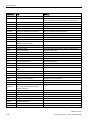
Table of contents
Preface ................................................................................................................................................... 3
1
2
3
4
Overview................................................................................................................................................. 9
1.1
1.1.1
1.1.2
1.1.3
Product description ................................................................................................................... 9
Highlights ................................................................................................................................10
Function ..................................................................................................................................11
Features ..................................................................................................................................12
1.2
1.2.1
1.2.2
1.2.3
Design of the device ...............................................................................................................16
Device views ...........................................................................................................................16
Interfaces ................................................................................................................................17
Status displays ........................................................................................................................19
1.3
Accessories .............................................................................................................................22
Safety Instructions ................................................................................................................................ 25
2.1
General safety instructions .....................................................................................................25
2.2
Notes on use ...........................................................................................................................29
Installing and connecting the device ...................................................................................................... 33
3.1
3.1.1
3.1.2
3.1.3
Preparing for installation .........................................................................................................33
Checking the delivery package ...............................................................................................33
Identification data of the device ..............................................................................................34
Permitted mounting positions .................................................................................................35
3.2
3.2.1
Mounting the device ................................................................................................................36
Installation guidelines..............................................................................................................36
3.3
3.3.1
3.3.2
3.3.3
3.3.4
3.3.4.1
3.3.4.2
3.3.4.3
3.3.5
3.3.6
3.3.6.1
3.3.6.2
3.3.7
Connecting the device ............................................................................................................38
Connection information ...........................................................................................................38
Connection of equipotential bonding ......................................................................................39
Connecting peripheral equipment ...........................................................................................40
Connecting the power supply .................................................................................................41
Information about the power supply ........................................................................................41
Connecting an AC power supply ............................................................................................42
Connecting a redundant power supply ...................................................................................43
Connecting the device to networks .........................................................................................44
Securing the lines ...................................................................................................................47
Network and fieldbus cables ...................................................................................................47
COM, DP, DVI/VGA, PS/2 and audio lines .............................................................................48
Multi-monitoring ......................................................................................................................48
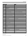
Commissioning the device .................................................................................................................... 49
4.1
General information on commissioning ..................................................................................49
4.2
Switching on the device ..........................................................................................................50
4.3
Automatic switching on of the device......................................................................................51
4.4
4.4.1
4.4.2
Notes on different device configurations.................................................................................51
Opening the front door ............................................................................................................51
DVD burner drive ....................................................................................................................52
SIMATIC IPC647D
Operating Instructions, 01/2015, A5E32996306-AB
5
Table of contents
5
6
7
4.4.3
4.4.4
4.4.5
4.4.5.1
4.4.5.2
4.4.5.3
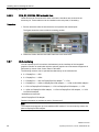
Hard disks in removable rack................................................................................................. 53
System with two drives .......................................................................................................... 54
RAID systems ........................................................................................................................ 55
Manage RAID system ............................................................................................................ 55
RAID1 system ........................................................................................................................ 56
Hardware RAID system ......................................................................................................... 56
4.5
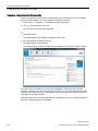
Windows Action Center .......................................................................................................... 59
4.6
Switching off the device ......................................................................................................... 59
Extended device functions .................................................................................................................... 61
5.1
5.1.1
5.1.2
5.1.3
5.1.4
5.1.5
5.1.6
Monitoring functions ............................................................................................................... 61
Overview of the monitoring functions ..................................................................................... 61
Temperature monitoring/display ............................................................................................ 62
Watchdog (WD) with LED ...................................................................................................... 62
Fan monitoring ....................................................................................................................... 63
Battery monitoring .................................................................................................................. 64
Drive monitoring ..................................................................................................................... 64
5.2
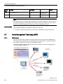
Active Management Technology (AMT) ................................................................................ 64
5.3
Trusted Platform Module (TPM) ............................................................................................. 66
Expanding and assigning parameters to the device ............................................................................... 67
6.1
Retrofitting instructions .......................................................................................................... 67
6.2
Removing the front panel ....................................................................................................... 69
6.3
Open the device. .................................................................................................................... 70
6.4
Removing and installing memory modules ............................................................................ 71
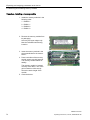
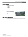
6.5
6.5.1
6.5.2
6.5.3
6.5.4
6.5.4.1
6.5.4.2
6.5.4.3
Expansion cards..................................................................................................................... 74
Notes on the expansion cards ............................................................................................... 74
Removing and installing bus frame ........................................................................................ 75
Removing and installing expansion cards ............................................................................. 76
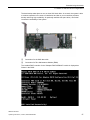
Removing and installing the Hardware RAID adapter card ................................................... 79
Requirement........................................................................................................................... 79
Procedure............................................................................................................................... 81
Configuring the Hardware RAID adapter card ....................................................................... 83
6.6
6.6.1
6.6.2
6.6.3
6.6.4
6.6.5
6.6.6
6.6.7
6.6.8
6.6.8.1
6.6.8.2
Drives and storage media ...................................................................................................... 84
Overview ................................................................................................................................ 84
Removing and installing drive cage ....................................................................................... 85
Removing and installing drive fans ........................................................................................ 87
Removing and inserting the tray from the removable drive bays .......................................... 89
Removing and installing the hard disk drive from a tray ........................................................ 90
Removing and installing a drive from a drive cage ................................................................ 91
Replacing a defective hard disk drive in the RAID system .................................................... 92
Removing and installing an SSD ........................................................................................... 93
Removing and installing an SSD from a tray ......................................................................... 93
Removing and installing an SSD with mounting plate from a drive cage .............................. 94
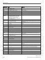
Device maintenance and repair ............................................................................................................. 95
7.1
Repair information .................................................................................................................. 95
7.2
7.2.1
Maintenance........................................................................................................................... 96
Maintenance intervals ............................................................................................................ 96
SIMATIC IPC647D
6
Operating Instructions, 01/2015, A5E32996306-AB
Table of contents
8
7.2.2
Changing the filter pad ............................................................................................................96
7.3
7.3.1
7.3.2
7.3.3
7.3.4
7.3.5
7.3.6
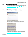
Manage onboard RAID system ...............................................................................................97
Example for a RAID1 system during the boot phase of the system .......................................98
RAID software .........................................................................................................................98
Checking the status of the RAID system ................................................................................99
Displaying a defective hard disk of a RAID system in the RAID software ..............................99
Special feature: Replacing hard disk in the RAID system when switched off ......................100
Integrating a new hard disk drive in the RAID system ..........................................................100
7.4
7.4.1
Managing the Hardware RAID system .................................................................................103
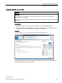
Calling Adaptec maxView Storage Manager ........................................................................103
7.5
7.5.1
7.5.2
7.5.3
7.5.4
7.5.5
7.5.6
7.5.7
7.5.8
7.5.9
7.5.10
Removing and installing hardware........................................................................................104
Replacing device fans ...........................................................................................................104
Replacing the backup battery ...............................................................................................105
Replace AC power supply ....................................................................................................108
Replacing the redundant power supply module ...................................................................109
Replacing the redundant power supply completely ..............................................................110
Removing and installing the piggyback and bus board ........................................................112
Removing the OP..................................................................................................................113
Removing and installing the processor cooler ......................................................................115
Removing the motherboard ..................................................................................................117
Replacing the processor .......................................................................................................119
7.6
7.6.1
7.6.2
7.6.3
7.6.4
7.6.5
7.6.6
7.6.7
7.6.8
7.6.9
7.6.10
Installing the software ...........................................................................................................121
Sources for installation of the operating system ...................................................................121
Updating the operating system .............................................................................................122
Installing drivers and software ..............................................................................................122
Installing Windows ................................................................................................................123
Setting up the language selection using the Multilanguage User Interface (MUI) ...............128
Restoring the delivery state ..................................................................................................129
Installing onboard RAID controller software .........................................................................131
Installing Hardware RAID controller software .......................................................................131
Backing up data and changing partitions at a later time .......................................................131
CP 1616 onboard ..................................................................................................................132
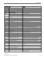
Technical specifications ...................................................................................................................... 133
8.1
Certificates and approvals ....................................................................................................133
8.2
8.2.1
Directives and declarations ...................................................................................................134
ESD guideline .......................................................................................................................135
8.3
8.3.1
8.3.2
8.3.3
Dimension drawings..............................................................................................................137
Dimensional drawing of the device .......................................................................................137
Dimension drawing of the telescopic rails.............................................................................138
Dimension drawing of the expansion cards ..........................................................................138
8.4
8.4.1
8.4.2
8.4.3
8.4.4
8.4.5
Technical specifications ........................................................................................................139
General specifications...........................................................................................................139
Current and power requirements ..........................................................................................145
Power supply (AC) ................................................................................................................146
AC power supply, redundant ................................................................................................147
Technical data of the telescopic rails ....................................................................................148
8.5
8.5.1
8.5.1.1
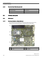
Hardware description ............................................................................................................148
Motherboard ..........................................................................................................................148
Structure and functions of the motherboard .........................................................................148
SIMATIC IPC647D
Operating Instructions, 01/2015, A5E32996306-AB
7
Table of contents
A
B
8.5.1.2
8.5.1.3
8.5.1.4
8.5.1.5
8.5.2
8.5.2.1
8.5.2.2
8.5.3
8.5.3.1
8.5.3.2
8.5.4
8.5.4.1
8.5.4.2
8.5.5
8.5.5.1
8.5.5.2
8.5.5.3
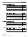
Technical features of the motherboard ................................................................................ 149
Position of the interfaces on the motherboard ..................................................................... 151
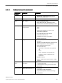
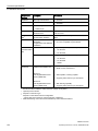
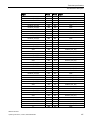
External interfaces ............................................................................................................... 152
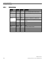
Internal ports ........................................................................................................................ 163
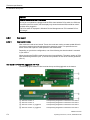
Bus board ............................................................................................................................. 170
Bus board models ................................................................................................................ 170
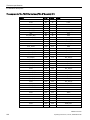
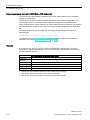
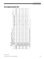
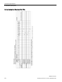
PCI hardware interrupts ....................................................................................................... 171
System resources ................................................................................................................ 176
Currently allocated system resources .................................................................................. 176
Allocation of the system resources used by BIOS/DOS ...................................................... 176
Displays and operator panel ................................................................................................ 181
Design and function ............................................................................................................. 181
Pin assignment of the OP connectors ................................................................................. 181
Communication processor CP 1616 onboard ...................................................................... 182
Introduction .......................................................................................................................... 182
Firmware loader ................................................................................................................... 184
Further actions in STEP 7/NCM PC..................................................................................... 186
8.6
8.6.1
8.6.2
8.6.3
8.6.4
8.6.5
8.6.6
8.6.7
8.6.7.1
8.6.7.2
BIOS description .................................................................................................................. 186
Overview .............................................................................................................................. 186
Opening the BIOS selection menu....................................................................................... 187
Configuration ........................................................................................................................ 188
Exit menu ............................................................................................................................. 189
BIOS update......................................................................................................................... 190
BIOS Setup settings ............................................................................................................. 191
Alarm, error and system messages ..................................................................................... 196
Power On Self Test .............................................................................................................. 196
BIOS beep codes ................................................................................................................. 198
8.7
8.7.1
8.7.2
8.7.3
8.7.4
8.7.5
8.7.6
8.7.7
Active Management Technology (AMT) .............................................................................. 204
AMT basics .......................................................................................................................... 204
Overview of AMT.................................................................................................................. 205
Enabling AMT, basic configuration ...................................................................................... 205
Advanced settings ................................................................................................................ 206
Resetting with Unconfigure .................................................................................................. 207
Determining the network address ........................................................................................ 207
Forcing user consent ........................................................................................................... 208
8.8
Assignment of expansion interface to the software in the TIA Portal (CP assignment) ...... 208
Technical support.................................................................................................................................209
A.1
Service and support ............................................................................................................. 209
A.2
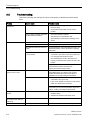
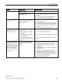
Troubleshooting ................................................................................................................... 210
A.3
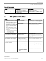
Troubleshooting status indicators ........................................................................................ 212
A.4
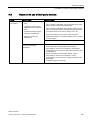
RAID system and device startup.......................................................................................... 213
A.5
Notes on the use of third-party modules .............................................................................. 215
Abbreviations .......................................................................................................................................217
Glossary ..............................................................................................................................................223
Index ...................................................................................................................................................235
SIMATIC IPC647D
8
Operating Instructions, 01/2015, A5E32996306-AB
1
Overview
1.1
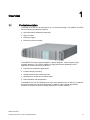
Product description
The SIMATIC IPC647D is an industrial PC in 19" rack format design. The SIMATIC IPC647D
has the following characteristic features:
● High-performance industrial functionality
● Highly compact
● Extremely rugged
● Extensive product continuity
The SIMATIC IPC offers system integrators, cabinet designers, system engineers and
machine designers a 19" rack PC platform for high-performance applications and IT
applications on the control and cell level for:
● Process and visualization applications
● Industrial image processing
● Quality assurance and monitoring tasks
● Measurement, control and rule-based tasks
● Data acquisition and management
The SIMATIC IPC has CE certification for use in the industrial sector as well as in residential
and commercial areas and small businesses. In addition to the industrial applications,
therefore, it can also be used in building automation or in public facilities.
SIMATIC IPC647D
Operating Instructions, 01/2015, A5E32996306-AB
9
Overview
1.1 Product description
1.1.1
Highlights
Highly compact
● Compact housing design (2 HU)
● Flexibility for space-saving cabinet installation
High degree of industrial capability
● High operational vibration and shock resistance
● Wide operational temperature range
● High service friendliness
● Dust protection
● Distinct diagnostic features
Ideal for industrial applications
● Integrated PROFIBUS DP / MPI interface (optional, compatible with CP5622)
● PROFINET interface CP 1616 onboard (optional)
● PCI, PCIe I/O, PEG slots
PEG graphics and onboard graphics can be used simultaneously
● High flexibility and expansibility of components
High investment protection
● High continuity of the components/design
● Guaranteed spare parts availability for at least 5 years
● Simple integration in PC-based automation
High system availability
● SIMATIC IPC DiagMonitor – PC diagnostics and message software via OPC/SNMP/LAN
● SIMATIC PC/PG Image Creator – data imaging software
● Optional ECC memory module
● Redundant power supply with status message
● RAID configurations: RAID controller onboard or powerful hardware RAID controllers
(PCIe x8) with Zero-Maintenance Cache Protection module
● RAID1 – redundant data storage on two hard drives, also "hot swap" in connection with
removable drive bays
(hot-spare equipment is supported)
SIMATIC IPC647D
10
Operating Instructions, 01/2015, A5E32996306-AB
Overview
1.1 Product description
1.1.2
Function
● Integral, configurable monitoring functions:
– Program execution (watchdog)
– Internal housing temperature
– Fan speed
● Enhanced diagnostic/messaging via Ethernet, E-mail, SMS, and for direct input in
SIMATIC software via OPC (optional using SIMATIC IPC DiagMonitor):
– Operating hours counter
– Hard disk status
– System status (heartbeat)
– Automatic logging of all messages to a log file
– Option of remote monitoring of networked SIMATIC IPCs
● RAID1 (mirroring): For automatic data mirroring on two hard disks. Configurations with
hot-spare drive available for order.
● Hardware RAID
– Auto-Rebuild for change of hard disk
– "Zero-Maintenance Cache Protection" protects the data in the hardware RAID
controller cache in the event of a power failure
– Reduced load on the main processor during the rebuild
– Fast 1 TByte SAS hard disks for maximum speed when reading and writing data
SIMATIC IPC647D
Operating Instructions, 01/2015, A5E32996306-AB
11
Overview
1.1 Product description
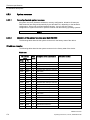
1.1.3
Features
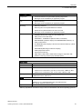
General features
Design
Enclosure
Drive bays
•
19” rack, 2 HU
•
Rugged panel-mount housing, all metal
•
Prepared for mounting telescopic rails
•
Can be mounted horizontally
•
Lockable front cover as access protection
•
Dust protection by means of overpressure ventilation using bearing seated
front fan through filter
•
Enclosure cover fastened with a single screw
•
Front fan can be exchanged without tools
•
Card retainer for reliable operation of PC modules under vibration and shock
conditions
•
2 × removable drive bays, slimline
or
•
2 × 3.5" drive in vibration-damped drive cage
and
•
1 × slimline DVD format
Slots for expansion cards (long)
Max. 4 slots 1, equipment PCI/PCIe, depending on configuration
Graphics
•
CRT (via DVI-I VGA adapter): Up to 2560x1600 at 120 Hz / 32-bit color depth
•
LCD via DVI-D: Up to 2048 x 1152 at 60 Hz, 32-bit color depth
•
LCD via DisplayPort: Up to 4096 x 1152 at 24 Hz, 32-bit color depth
Interfaces
1
PROFIBUS/MPI
12 Mbps (isolated potential, compatible to CP -5622), optional
PROFINET
10/100 Mbps (CP 1616 onboard), three RJ45; optional
Ethernet
2 x 10/100/1000 Mbps (two RJ45)
Wake on LAN, Remote Boot and teaming are supported
USB
2 x front panel, 4 x rear panel, 1 x internal; (high current)
Serial
COM1 (V.24), COM2 (V.24) optional, through slot plate adapter
Parallel
LPT optional, through slot plate adapter
Monitor
•
1 x DVI-I (for DVI-D or VGA using cable adapter)
•
2 × DisplayPort
•
2 × DVI-D/VGA with Dual Head graphics card (optional, via cable adapter)
Keyboard
PS/2
Mouse
PS/2
Audio
Microphone, Line out / Headset
Power supply
100 VAC to 240 VAC, wide range; with short-term power failure backup in accordance with NAMUR: Max. 20 ms at 0.85 rated voltage
The optional hardware RAID controller occupies two slots
SIMATIC IPC647D
12
Operating Instructions, 01/2015, A5E32996306-AB
Overview
1.1 Product description
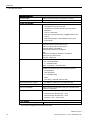
Monitoring functions
Temperature
Fan
Watchdog
Status LEDs
•
Overshoot/undershoot of permissible operating temperature
•
Messages can be evaluated by an application program.
•
Speed monitoring
•
Messages can be evaluated by an application program.
•
Monitoring of the IPC
•
Monitoring time can be parameterized in software
•
Restart can be parameterized in the event of a fault
•
Messages can be evaluated by an application program.
•
POWER (internal power supply unit, PC switched On)
•
HDD (access to hard disk drive)
•
ETHERNET 1, ETHERNET 2 (Ethernet status, "heartbeat")
•
PROFIBUS/MPI (activation display of the PROFIBUS/MPI interface), optional product feature
•
SF PROFINET (status display of the CP 1616 onboard interface), optional
product feature
•
WATCHDOG (Watchdog function/error display)
•
TEMP (temperature status)
•
FAN (speed monitoring)
•
HDD0 Alarm, HDD1 Alarm: RAID status message in conjunction with
SIMATIC monitoring software (only with RAID option)
Basic variant
Motherboard
Motherboard without fieldbus, Intel® DH82C226 Express Chipset
Bus board
PCI, PCIe x4, PCIe x16, 2 variants
Processor
•
Intel® Xeon™ E3-1268L v3 2.3 (3.3) GHz, 4 cores, GT2, 8 MB SLC, HT
•
Intel® Core™ i5-4570TE 2.7 (3.3) GHz, 2 cores, GT2, 4 MB SLC, AMT
•
Intel® Core™ i3-4330TE 2.4 GHz, 2 cores, GT2, 3 MB SLC, AMT
RAM expansion
Up to 32 GB SDRAM DDR3 1600MT/s
4 DIMM base with or without ECC 1
Drives
Hard disks
3.5" SATA 6 Gbit/s or SAS, 500 GB / 1000 GB
Maximum 4 × 3.5" SAS hard disks in the removable drive bay
The quantity depends on the IPC type
Optical drive
1 Memory
Slimline SATA
expansions ≥4 GB can only be used in combination with 64-bit operating systems.
SIMATIC IPC647D
Operating Instructions, 01/2015, A5E32996306-AB
13
Overview
1.1 Product description
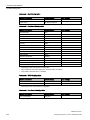
Optional accessories
PROFIBUS/MPI
12 Mbps (isolated potential, compatible to CP 5622)
PROFINET
10/100 Mbps (CP 1616 onboard, three RJ45)
Drives, RAID controller
SAS Hardware RAID controller
DVD burner
•
PCIe x8 expansion card
The adjacent slot must remain free.
•
Intelligent PCIe x8 RAID controller type: PMC Sierra
ASR-8405
for max. 4 SAS drives
•
With CPU, cache memory (thus, negligible effect on the
system)
•
With battery backup for data reliability in the event of
power failures
Read:
DVD ROM: Single Layer8x, Dual Layer 6x
DVD-R/+R: Single layer 8x, Dual layer 6x
DVD-RW/+RW 8x, DVD-RAM 5x
CD-ROM/CD-R Read 24x, CD-RW 24x
Write:
DVD+R 8x, DVD+RW 8x, DVD-R 8x, DVD-RW 6x
DVD+R (DL) 6x, DVD-R DL 2x
CD-R 24x, CD-RW 24x
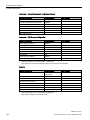
Hard disks 3.5" (SATA or SAS)
Installation in drive cage (with vibration damping)
•
500 / 1000 GB (SATA)
• 2 × 1000 GB (SATA)
RAID1: 1000 GB (2 × 1000 GB, SATA)
Installation in the drive cage of the removable drive bay
•
500 GB (SATA)
•
1000 GB (SATA)
•
2 × 1000 GB (SATA)
•
RAID1:
1000 GB (2 × 1000 GB, SATA or SAS)
Solid State Drive 2.5" (SATA)
•
Graphics cards
PCIe x16 graphics card, dual head (2 x VGA or 2 x DVI-D)
DVI-I to VGA adapter
Used to connect a monitor with a VGA port to the PC (can be
ordered by configurator).
Operating system
Preinstalled and activated, included on restore DVD
240 GB MLC, internal or in removable drive bay
•
Windows Server 2008 R2, MUI 1, 64 bit
•
Windows Server 2012 R2, MUI 1, 64 bit
•
Windows 7, MUI 1, 32 bit / 64 bit
Power supplies
Redundant AC power supply
1
Monitored AC-100/230 V power supply, 350 W
MUI: German, English, French, Spanish and Italian
SIMATIC IPC647D
14
Operating Instructions, 01/2015, A5E32996306-AB
Overview
1.1 Product description
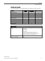
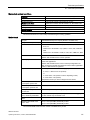
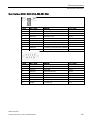
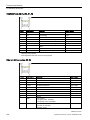
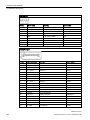
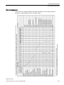
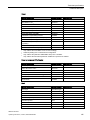
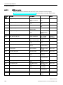
Operating system languages
The following languages for the operating system can be installed from the recovery DVD:
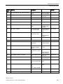
Language
Windows Server
2008 R2
Windows Server
2012 R2 UP1
Windows 7 32/64-bit
X
X
X
English (United States)
X
X
X
French (France)
X
X
X
Italian (Italy)
X
X
X
Spanish (Spain)
X
X
X
Japanese (Japan)
X
X
X
Korean (Korea)
-
X
-
Russian (Russia)
X
X
X
Chinese (PRC)
X
X
X
Chinese (Hong Kong S.A.R.)
X
X
X
Chinese (Taiwan)
X
X
X
German (Germany)
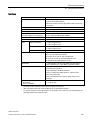
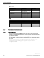
Optional software
SIMATIC IPC DiagMonitor V4.4.3 or
higher
SIMATIC IPC Image & Partition
Creator V3.3.3 or higher
Software for monitoring local and remote SIMATIC PCs:
•
Watchdog
•
Temperature
•
Fan speed
•
Hard disk monitoring (SMART, RAID status)
•
Monitoring modules of the redundant power supply
•
System / Ethernet monitoring (Heartbeat)
Software tool for local data backup and setting up of the hard
disks.
SIMATIC IPC647D
Operating Instructions, 01/2015, A5E32996306-AB
15
Overview
1.2 Design of the device
1.2
Design of the device
1.2.1
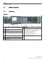
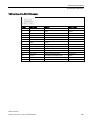
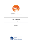
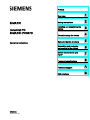
Device views
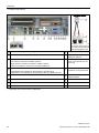
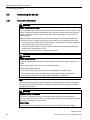
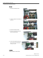
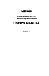
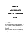
Front view
①
Front panel with openings for ventilation of the device
②
Rating plate
③
Front door
④
Status displays
⑤
Reset button
⑥
USB 2.0 port
⑦
USB 3.0 port
⑧
On/off button
⑨
Installation option for drives
⑩
The following drives can be ordered optionally:
•
HDD or SSD in removable drive bay
•
DVD burner drive, Slimline
•
HDD in vibration-damped drive cage
•
SSD in internal drive cage
Lock for front door
SIMATIC IPC647D
16
Operating Instructions, 01/2015, A5E32996306-AB
Overview
1.2 Design of the device
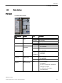
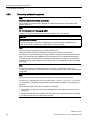
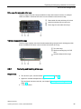
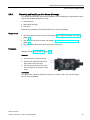
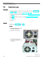
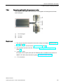
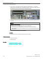
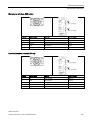
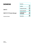
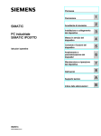
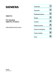
Rear view with AC power supply
①
AC power supply
②
Power supply
connection
③
On/off switch
④
Interfaces (Page 17)
⑤
Expansion card slots
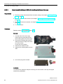
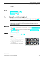
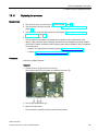
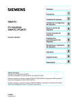
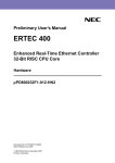
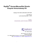
Rear view with redundant power supply
1.2.2
①
Power supply
connection
②
Acknowledgment
button
③
Module 1 of the
redundant power
supply
④
Module 2 of the
redundant power
supply
⑤
On/off switch
⑥
Status LED module 1
⑦
Interfaces (Page 17)
⑧
Expansion card slots
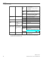
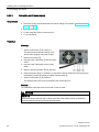
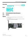
Interfaces
SIMATIC IPC647D
Operating Instructions, 01/2015, A5E32996306-AB
17
Overview
1.2 Design of the device
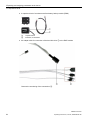
Dual-head adapter
The adapter is necessary if
you want to connect one of
two monitors to the optional
Dual Head graphics card.
①
Connection for equipotential bonding
②
Fieldbus cover: No fieldbus, PROFIBUS or
③
USB ports
PROFINET 1
Left sockets: Connection for USB 2.0 devices
⑨
DVI-I port
⑩
Slot plate adapter with LPT and
COM2 port, optional
⑪
Audio input for analog audio
source or microphone, 3.5 mm
phono jack
⑫
Audio output for active speakers
or headset, 3.5 mm phono jack
Right sockets: Connection for USB 3.0 / USB 2.0 devices
USB 2.0 and USB 3.0 connections use different USB ports.
④
ETHERNET interfaces 1 and 2
⑤
COM interface
⑬
Slots for expansion cards
(behind slot plate)
⑥
DisplayPort port
⑭
DMS59 connector
⑦
PS/2 interface for keyboard
⑮
DVI-I connector
⑧
PS/2 interface for mouse
⑯
VGA adapter
1
LAN interfaces are numbered on the enclosure to provide unique
identification. The numbering by the operating system may deviate from this.
Depending on the ordered device configuration
SIMATIC IPC647D
18
Operating Instructions, 01/2015, A5E32996306-AB
Overview
1.2 Design of the device
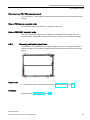
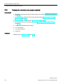
1.2.3
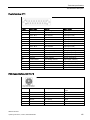
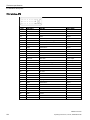
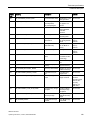
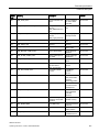
Status displays
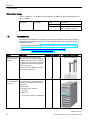
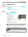
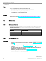
Front panel
View with open front door
Operating display
Meaning
LED
Description
POWER
Operating mode of
the PC
OFF
PC disconnected from power supply
YELLOW
PC in standby
GREEN
PC in operation
OFF
No access
GREEN
Access of onboard SATA hard disk
OFF
•
No connection
GREEN
•
Connection
•
No data traffic
•
Connection
•
Data traffic
•
No connection
•
No data traffic
HDD
ETHERNET 1
ETHERNET 2
Access to hard disk
1
Status connection
ETHERNET
Flashes
GREEN
according to
activity
1
PROFIBUS/MPI
(optional)
SF PROFINET,
optional
Status connection S7 OFF
or PROFIBUS
Status
CP 1616 onboard
GREEN
Data traffic
OFF
•
CP not available
•
CP disabled
•
No error, communication established
•
Charging in progress
•
CP 1616 driver not installed
•
CP in NDIS mode
SIMATIC IPC647D
Operating Instructions, 01/2015, A5E32996306-AB
19
Overview
1.2 Design of the device
Flashes
slowly
RED
Flashes
rapidly
•
Link status error
•
IO controller: IO device cannot be
addressed
•
IO controller: Duplicate IP address
Exception error: diagnostics via Web or
SNMP is no longer possible
RED
RED
WATCHDOG
TEMP
FAN
HDD0 ALARM
HDD1 ALARM
All displays are
lit
1
WATCHDOG status
Temperature status
Fan status
•
Diagnostics information available
•
No communication established.
OFF
WATCHDOG not activated
GREEN
WATCHDOG monitoring enabled
RED
Monitoring time elapsed
OFF
Internal temperature OK
RED
Internal temperature critical
OFF
Fan speed OK
(only with active SOM RED
or DiagMonitor
software)
Fan speed too low
HDD alarm in connection with RAID
and monitoring software
RAID is OK
Error in early BIOS
Post
OFF
RED, 1 ×
HDD0 or HDD1 not OK
RED, 2 ×
RAID is not OK
Localization of the hard disk see Section
"Displaying a defective hard disk of a RAID
system in the RAID software (Page 99)"
Both flash
RAID synchronization in progress
All lit
CPU has not started up
Error in early POST
For unique labeling, the Ethernet ports are numbered on the enclosure. The numbering by the
operating system may deviate from this.
SIMATIC IPC647D
20
Operating Instructions, 01/2015, A5E32996306-AB
Overview
1.2 Design of the device
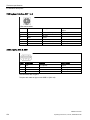
Ethernet interface
Display
Ethernet 1, 2
1
Meaning
LED
Description
Green LED
Off
•
Link status display
Yellow LED
Yellow LED
Activity status display of
CP-1616 channel
100 Mbit cable active
1000 Mbit cable active
Off
•
No cable connected
•
Cable disabled
•
Interface disabled
•
Connection
•
No activity
Goes out briefly
Activity
Off
•
No cable connected
•
Cable disabled
•
Interface disabled
Green
Active cable connected
Off
•
No cable connected
•
Cable disabled
•
Interface disabled
•
Connection
•
No activity
Lit
Goes out briefly
1
Cable disabled
Interface disabled, 10 MBit
cable active
Orange
Lit
Green LED
Link status display of
CP-1616 channel
•
•
Green
Activity status display
PROFINET LAN X1
P1, P2, P3 1
No cable connected
Activity
For unique labeling, the LAN and PROFINET interface are numbered on the enclosure. The numbering by the operating system may deviate from this.
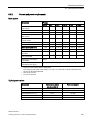
Drives in removable rack
①
②
"Power" LED; power supply available
"HDD" LED, access to hard disk drive
SIMATIC IPC647D
Operating Instructions, 01/2015, A5E32996306-AB
21
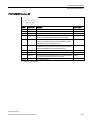
Overview
1.3 Accessories
Virtual status display
The two "virtual" CP -1616 LEDs are only visible in the SIMATIC user interface and can be
read via SNMP.
PROFINET
1.3
Virtual LEDs
RUN
CP is active
STOP
CP is in the stop state
Flashes
The states "flashes slowly" and
"flashes rapidly" do not exist.
Accessories
Accessories are available for your device. These are not included in the scope of delivery.
Information on available accessories is listed in the table below and on the Internet at the
following addresses:
● IPC expansion components (http://www.automation.siemens.com/mcms/pc-basedautomation/en/industrial-pc/expansion_components_accessories)
● Industry Mall (https://mall.industry.siemens.com)
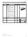
Name
Description
Retainer for locking The retainer is a mechanical safety
the internal USB
device for the internal USB interface. It
interface
optimizes the protection of an internal
USB memory stick against loads caused
by vibration and shock during transportation or operation.
IPC647D
IPC847D
Article number and figure
x
x
6ES7648-1AA00-0XK0
-
x
6ES7648-1AA00-0XD0
This increases the reliability and operational safety of the device.
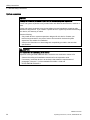
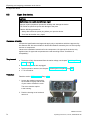
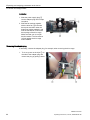
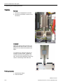
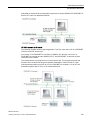
Tower Kit
(not available in all
countries)
You can use the Tower Kit to convert
the device into an industrial Tower PC.
This step expands the operating range
beyond the
control cabinet.
Components of the Tower Kit:
•
Cover ①
•
Base ②
•
Accessories: Screws and rubber feet
SIMATIC IPC647D
22
Operating Instructions, 01/2015, A5E32996306-AB
Overview
1.3 Accessories
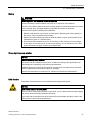
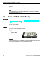
Name
Description
Tray for low-profile
removable drive
bay
The removable drive bay makes for
quick and simple replacement of a 3.5''
hard disk or 2.5" SSD without having to
open the device or
remove it from the control cabinet. The
result is the following advantages for
service and maintenance, data backup
and data transfer:
•
Replacement of a failed hard disk in
operation ("hot swap") in RAID
configurations
•
Downloading different system states
or operating systems from different
hard drives during a short period of
time.
•
Simplified data backup by copying,
for
example, to a backup hard drive.
•
Simple transportation of backup data
•
Separate data storage and archiving
possible
IPC647D
IPC847D
Article number and figure
x
x
6ES7648-0EG01-1BA0
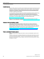
VGA / DVI adapter
Graphics adapter cable DVI-I to VGA,
250 mm long
x
x
6ES7648-3AB00-0XA0
DP / DVI adapter
Graphics adapter cable, DisplayPort to
DVI
x
x
6ES7648-3AF00-0XA0
DP / VGA adapter
Graphics adapter cable, DisplayPort to
VGA
x
x
6ES7648-3AG00-0XA0
SIMATIC IPC647D
Operating Instructions, 01/2015, A5E32996306-AB
23
Overview
1.3 Accessories
SIMATIC IPC647D
24
Operating Instructions, 01/2015, A5E32996306-AB
Safety Instructions
2.1
2
General safety instructions
Fully disconnecting the device from mains voltage
WARNING
Risk of fire and electric shock
The on/off button and on/off switch do not fully disconnect the device from the mains. If the
device is switched off with the on/off switch, there remains a risk of electric shock and fire
hazard, for example, if the device or connection cables are damaged or if the device is
used improperly.
Always fully disconnect the device from the mains voltage as follows before performing
work on the device or when the device will not be used over an extended period of time.
• If the device was not mounted in a control cabinet: Shut down the operating system and
pull the power plug on the rear of the device.
• If the device was mounted in a control cabinet: Shut down the operating system and
switch the AC circuit breaker to "Off".
• Properly connect the device to a protective conductor.
Devices in the control cabinet
WARNING
Life-threatening voltages are present with an open control cabinet
When you open the control cabinet, some areas or components may be carrying lifethreatening voltages.
If you touch these areas or components, you may be killed by electric shock.
Switch off the power supply to the cabinet before opening it.
SIMATIC IPC647D
Operating Instructions, 01/2015, A5E32996306-AB
25
Safety Instructions
2.1 General safety instructions
System expansions
NOTICE
Damage to the device, machine or plant due to device and system expansions
Device and system expansions may contain faults and affect the entire device, machine or
plant.
Device and system expansions may violate safety rules and regulations regarding radio
interference suppression. If you install or replace device or system expansions and damage
your device, the warranty is voided.
Note the following:
• Only install device or system expansions designed for this device. Contact your
technical support team or the point of sale to find out which device and system
expansions are suitable for installation.
• Observe the information on electromagnetic compatibility provided in the technical
specifications.
CAUTION
Fire hazard due to overheating of the device
Expansion cards generate additional heat. The device can overheat or cause a fire.
• Observe the safety and installation instructions for the expansion cards.
• If necessary, install the device in an enclosure that meets the requirements of
paragraphs 4.6 and 4.7.3 of the standards EN 60950-1:2006 and
IEC/UL/EN/DIN-EN 60950-1.
SIMATIC IPC647D
26
Operating Instructions, 01/2015, A5E32996306-AB
Safety Instructions
2.1 General safety instructions
Battery
WARNING
Risk of explosion and release of harmful substances
Improper handling of lithium batteries can result in an explosion of the batteries.
Explosion of the lithium batteries and the resulting release of harmful substances can cause
severe physical injury. Damaged batteries jeopardize the function of the device.
Note the following when handling lithium batteries:
• Replace used batteries in good time; see the section "Replacing the backup battery" in
the section "Device maintenance and repair".
• Replace the lithium battery only with an identical battery or types recommended by the
manufacturer (order no.: A5E00047601).
• Do not throw lithium batteries into fire, do not solder on the cell body, do not recharge,
do not open, do not short-circuit, do not reverse polarity, do not heat above 100°C and
protect from direct sunlight, moisture and condensation.
Strong high-frequency radiation
NOTICE
Observe immunity to RF radiation
The device has an increased immunity to RF radiation according to the specifications on
electromagnetic compatibility in the technical specifications.
Radiation exposure in excees of the specified immunity limits can impair device functions,
result in malfunctions and therefore injuries or damages.
Observe the information on immunity to RF radiation in the technical specifications.
ESD directive
Electrostatic sensitive devices can be labeled with an appropriate symbol.
NOTICE
Electrostatic sensitive devices (ESD)
When you touch electrostatic sensitive components, you can destroy them through voltages
that are far below the human perception threshold.
If you work with components that can be destroyed by electrostatic discharge, observe the
ESD directive in the technical specifications.
SIMATIC IPC647D
Operating Instructions, 01/2015, A5E32996306-AB
27
Safety Instructions
2.1 General safety instructions
Industrial Security
Siemens offers products and solutions with Industrial Security functions that support the safe
operation of equipment, solutions, machines, devices and/or networks. They are important
components in a comprehensive Industrial Security concept. As a result the products and
solutions from Siemens are constantly evolving. Siemens recommends obtaining regular
information regarding product updates.
For safe operation of Siemens products and solutions appropriate protective measures (e.g.,
cell protection concept) must be taken and each component must be integrated in a
comprehensive Industrial Security concept, which corresponds with the current state of
technology. The products of other manufacturers need to be taken into consideration if they
are also used. You can find addition information on Industrial Security under
(http://www.siemens.com/industrialsecurity).
Sign up for our product-specific newsletter to receive the latest information on product
updates. For more information, see under (http://www.siemens.de/automation/csi_en_WW).
Disclaimer for third-party software updates
This product includes third-party software. Siemens AG only provides a warranty for
updates/patches of the third-party software, if these have been distributed as part of a
Siemens software update service contract or officially released by Siemens AG. Otherwise,
updates/patches are undertaken at your own risk. You can find more information about our
Software Update Service offer on the Internet at Software Update Service
(http://www.automation.siemens.com/mcms/automation-software/en/software-updateservice/Pages/Default.aspx).
Notes on protecting administrator accounts
A user with administrator privileges has extensive access and manipulation options in the
system.
Therefore, ensure there are adequate safeguards for protecting the administrator accounts
to prevent unauthorized changes. To do this, use secure passwords and a standard user
account for normal operation. Other measures, such as the use of security policies, should
be applied as needed.
SIMATIC IPC647D
28
Operating Instructions, 01/2015, A5E32996306-AB
Safety Instructions
2.2 Notes on use
Access protection
CAUTION
Protection against access by unauthorized persons
An unauthorized user can operate the device incorrectly and bypass logon by restarting the
device.
Operator actions by unauthorized persons jeopardize operational reliability.
Take the following safety precautions:
• Lock the front door and the removable drive bay.
• Do not use keyboards with an on/off button (Power button).
• If the device has a on/off button, assign the parameters of the function of the on/off
button to meet your requirements under Windows. You can find the settings in the
"Power Options" menu.
Headphones
CAUTION
Impaired hearing due to excessive sound pressure
The setting of the volume and the equalizer can increase the sound pressure in the
headphones. Other factors not mentioned by the manufacturer can also influence the
sound pressure, for example, the operating system, equalizer software, firmware and
driver.
Excessive sound pressure from headphones can result in impaired hearing or even loss of
hearing.
Set the volume control and equalizer to the lowest value before you put on the
headphones. Keep checking the volume control setting. Only use headphones and
software approved by the manufacturer.
2.2
Notes on use
NOTICE
Possible functional restrictions in case of non-validated plant operation
The device is tested and certified on the basis of the technical standards. In rare cases,
functional restrictions can occur during plant operation.
Validate the correct functioning of the plant to avoid functional restrictions.
SIMATIC IPC647D
Operating Instructions, 01/2015, A5E32996306-AB
29
Safety Instructions
2.2 Notes on use
NOTICE
Rack-mount instructions
A) Elevated Operating Ambient - If installed in a closed or multi-unit rack, the operating
ambient temperature of the rack environment may be greater than the room ambient.
Therefore consideration should be given to installing the equipment in an environment
compatible with the maximum ambient temperature (Tma) specified by the manufacturer.
B) Reduced Air Flow - Installation of the equipment in a rack should be such that the
amount of air flow required for safe operation of the equipment is not compromised.
C) Mechanical Loading - Mounting of the equipment in the rack should be such that a
hazardous condition is not achieved due to uneven mechanical loading.
D) Circuit Overloading - Consideration should be given to the connection of the equipment
to the supply circuit and the effect that overloading of the circuits might have on overcurrent
protection and supply wiring. Appropriate consideration of equipment nameplate ratings
should be used when addressing this concern.
E) Reliable Earthing - Reliable earthing of rack-mounted equipment should be maintained.
Particular attention should be given to supply connections other than direct connections to
the branch circuit (e. g. use of power strips).
Note
Use in an industrial environment without additional protective measures
This device was designed for use in a normal industrial environment according to
IEC 60721-3-3.
Ambient and environmental conditions
WARNING
Voided approvals
If the following conditions for system installation are not observed, approvals in accordance
with UL 60950-1 and EN 60950-1 are rendered void and there is a risk of overheating and
personal injury.
NOTICE
Damage of device caused by ambient conditions
Ambient conditions for which the device is not suitable can cause faults or damage the
device.
Note the following:
• Operate the device only in closed rooms. Failure to comply nullifies the warranty.
• Operate the device only in accordance with the ambient conditions.
• Observe the permitted mounting positions of the device.
SIMATIC IPC647D
30
Operating Instructions, 01/2015, A5E32996306-AB
Safety Instructions
2.2 Notes on use
When you plan your project, you should make allowances for:
● Climatic and mechanical environmental conditions defined in the "General technical data"
chapter of the operating instructions.
● This device was designed for use in a normal industrial environment. SIMATIC Rack PCs
may not be operated in severe environments which are subject to caustic vapors or
gases without taking additional protective measures (such as the provision of clean air.)
● Avoid extreme ambient conditions as far as possible, for example, heat.
● Do not expose the device to direct sunlight or other powerful light sources.
● Install the device in such a way that it poses no danger, for example, by falling over.
● The device conforms to protection class IP41 at the front panel. Ensure that the
installation opening for the device is splash-proof in areas which may be subject to splash
water.
● Always maintain a minimum clearance of 50 mm to the area of the ventilation slots in
order to ensure adequate ventilation of the PC.
● Do not cover the ventilation slots of the enclosure. There must be distance of at least 5
cm at the back of the device, depending on wiring.
● The device meets requirements for fire protection housings to EN 60950-1 and can be
installed without additional fire protection enclosure.
● The connected or built-in peripherals should not introduce a counter emf in excess of
0.5 V into the device.
SIMATIC IPC647D
Operating Instructions, 01/2015, A5E32996306-AB
31
Safety Instructions
2.2 Notes on use
SIMATIC IPC647D
32
Operating Instructions, 01/2015, A5E32996306-AB
Installing and connecting the device
3.1
Preparing for installation
3.1.1
Checking the delivery package
3
Procedure
1. When accepting a delivery, please check the packaging for visible transport damage.
2. If any transport damage is present at the time of delivery, lodge a complaint at the
shipping company in charge. Have the shipper confirm the transport damage
immediately.
3. Unpack the device at its installation location.
4. Keep the original packaging in case you have to transport the unit again.
Note
Damage to the device during transport and storage
If a device is transported or stored without packaging, shocks, vibrations, pressure and
moisture may impact the unprotected unit. Damaged packaging indicates that ambient
conditions have already had a massive impact on the device and it may be damaged.
This may cause the device, machine or plant to malfunction.
• Keep the original packaging.
• Pack the device in the original packaging for transportation and storage.
5. Check the contents of the packaging and any accessories you may have ordered for
completeness and damage.
6. Please inform the delivery service immediately if the package contents are incomplete or
damaged or do not correspond with your order. Fax the enclosed form "SIMATIC IPC/PG
Quality Control Report".
WARNING
Electric shock and fire hazard due to damaged device
A damaged device can be under hazardous voltage and trigger a fire in the machine or
plant. A damaged device has unpredictable properties and states.
Death or serious injury could occur.
Make sure that the damaged device is not inadvertently installed and put into operation.
Label the damaged device and keep it locked away. Send off the device for immediate
repair.
SIMATIC IPC647D
Operating Instructions, 01/2015, A5E32996306-AB
33
Installing and connecting the device
3.1 Preparing for installation
NOTICE
Damage from condensation
If the device is subjected to low temperatures or extreme fluctuations in temperature
during transportation, as is the case in cold weather, for example, moisture can build up
on or inside the device (condensation).
Moisture causes a short circuit in electrical circuits and damages the device.
In order to prevent damage to the device, proceed as follows:
• Store the device in a dry place.
• Bring the device to room temperature before starting it up.
• Do not expose the device to direct heat radiation from a heating device.
• If condensation develops, wait approximately 12 hours or until the device is
completely dry before switching it on.
7. Please keep the enclosed documentation in a safe place. It belongs to the device. You
need the documentation when you commission the device for the first time.
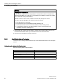
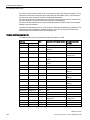
8. Write down the identification data of the device.
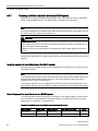
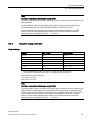
3.1.2
Identification data of the device
The device can be clearly identified with the help of this identification data in case of repairs
or theft.
Noting down the device identification data
Enter the following data in the table below:
Serial number
S VP ...
Order no.
6AG4112-2 ...
Microsoft Windows Product Key
Ethernet 1 address
Ethernet 2 address
CP 1616 onboard layer 2
SIMATIC IPC647D
34
Operating Instructions, 01/2015, A5E32996306-AB
Installing and connecting the device
3.1 Preparing for installation
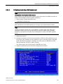
The data can be found as follows:
● Serial number: The serial number (S VP) is located on the rating plate either on the rear
panel of the device or on the inside of the front door.
● Order number of the device
● Device Ethernet address: The Ethernet address is printed on the device and is stored in
the BIOS Setup, "Advanced" menu, submenu "Peripheral Configuration".
● Microsoft Windows "Product Key" on the "Certificate of Authenticity" (COA). The COA
label is attached to the inside of the front door.
You may need the Product Key in case you reinstall the operating system.
Information on the device equipment is available on the inside of the front door.
3.1.3
Permitted mounting positions
Optional installation locations
The device can be mounted horizontally in control desks, switchboards and 19" rack
systems, and possibly vertically which is not permitted in all countries.
NOTICE
Operation in closed rooms
The device is approved for operation in closed rooms only. Pay attention to the ambient
and environmental conditions.
SIMATIC IPC647D
Operating Instructions, 01/2015, A5E32996306-AB
35
Installing and connecting the device
3.2 Mounting the device
3.2
Mounting the device
3.2.1
Installation guidelines
WARNING
Danger, high voltage
A high voltage may be present in the switchgear cabinet and could cause a dangerous
electric shock.
It may result in death or serious physical injury.
Isolate the power supply to the switchgear cabinet before opening it. Ensure that the power
to the switchgear cabinet cannot be turned on accidentally.
NOTICE
Fire hazard
If you install the device in an unapproved mounting position or if you do not observe the
ambient conditions, the device can overheat. UL approval and conformity with the lowvoltage directive (EN 60950-1:2006 and DIN EN 60950-1:2006-11) become void.
Overheating can cause a fire. Proper functioning of the device is no longer guaranteed.
Before you install the device, note the following general installation information.
Note
The device fulfills the requirements for a fire protection housing according to EN 60950-1.
Therefore, it can be installed without additional fire protection.
● Install the device only in one of the described permitted mounting positions.
● Provide adequate volume in the switchgear cabinet for air circulation and heat transport.
● Do not cover the ventilation slots of the device. There must be distance of at least 5 cm at
the back of the device, depending on wiring.
● Ensure that the maximum air intake temperature directly in front of the air intake opening
does not exceed the permitted temperature according to the technical specifications of
the device. The maximum air intake temperature must be accounted for especially when
sizing closed switchgear cabinets.
● Install the device in such a way that it does not pose a danger, for example, by falling
over.
Note
For more details, consult the "Technical Data" in the "Ambient conditions" chapter.
SIMATIC IPC647D
36
Operating Instructions, 01/2015, A5E32996306-AB
Installing and connecting the device
3.2 Mounting the device
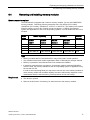
Mounting methods
You can mount the device as follows:
● Mounting with cabinet brackets
● Mounting on device bases
● Mounting on telescopic rails
When telescopic rails are used for mounting, the device can be withdrawn fully from the
cabinet or rack. You will find detailed information about the telescopic rails in sections
Technical data of the telescopic rails (Page 148) and Dimension drawing of the telescopic
rails (Page 138).
CAUTION
Risk of physical injury
The device is too heavy to be mounted exclusively with the 19 inch brackets of the front
panel. The device may fall down, injure people and get damaged.
Secure the device using additional measures. The mounting screws of the telescopic
rails may not protrude more than 5 mm into the device.
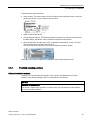
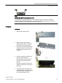
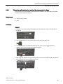
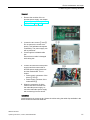
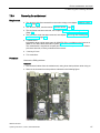
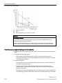
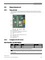
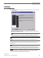
Position of the mounting holes for angle brackets or telescopic rails
The following figure highlights the mounting holes for the angle brackets and for the
telescopic rails.
The dimensions for the mounting holes are listed in the chapter "Dimension drawing of the
telescopic rails (Page 138)".
SIMATIC IPC647D
Operating Instructions, 01/2015, A5E32996306-AB
37
Installing and connecting the device
3.3 Connecting the device
3.3
Connecting the device
3.3.1
Connection information
WARNING
Risk of fire and electric shock
The on/off button and on/off switch do not fully disconnect the device from the mains. If the
device is switched off with the on/off switch, there remains a risk of electric shock and fire
hazard, for example, if the device or connection cables are damaged or if the device is
used improperly.
Always fully disconnect the device from the mains voltage as follows before performing
work on the device or when the device will not be used over an extended period of time.
• If the device was not mounted in a control cabinet: Shut down the operating system and
pull the power plug on the rear of the device.
• If the device was mounted in a control cabinet: Shut down the operating system and
switch the AC circuit breaker to "Off".
• Properly connect the device to a protective conductor.
WARNING
Risk of lightning strikes
A lightning flash may enter the mains cables and data transmission cables and jump to a
person.
Death, serious injury and burns can be caused by lightning.
Take the following precautions:
• Pull out the power plug in good time when a thunderstorm is approaching.
• Do not touch mains cables and data transmission cables during a thunderstorm.
• Keep sufficient distance from electric cables, distributors, systems, etc.
Note
Make sure that the shockproof power outlet of the building installation is freely accessible
and as close as possible to the device, especially when the power plug is secured with a
locking power plug latch.
WARNING
Operation only in TN networks
The device is designed for use on a grounded power supply grid (TN networks per
VDE 0100 Part 100 or IEC 60364-1). Operation with non-grounded or impedance-grounded
networks (IT networks) is not permitted.
Rated voltage
The permitted nominal voltage of the device must conform with local mains voltage.
SIMATIC IPC647D
38
Operating Instructions, 01/2015, A5E32996306-AB
Installing and connecting the device
3.3 Connecting the device
I/O devices
NOTICE
Fault caused by I/O devices
The connection of I/O devices can cause faults in the device. The result may be personal
injury and damage to the machine or plant. Note the following:
• Connect only I/O devices which are approved for industrial applications in accordance
with EN 61000-6-2/IEC 61000-6-2.
• Non-hot-plug capable I/O devices may only be connected when the power supply to the
device is switched off.
Damage through regenerative feedback
Regenerative feedback of voltage to ground by a connected or installed component can
damage the device.
Connected or built-in I/Os, for example, a USB drive, are not permitted to supply any
voltage to the device. Regenerative feedback is generally not permitted.
3.3.2
Connection of equipotential bonding
A low-resistance ground connection ensures that interference signals generated by external
power supply cables, signal cables or cables to the I/O modules are safely discharged to
ground.
The equipotential bonding connection of the device is located on the side of the device and
is identified by the following symbol:
Requirement
● TORX T20 screwdriver
● An equipotential bonding cable with a minimum cross-section of 2.5 mm2
Procedure
1. Connecting the equipotential bonding connection ① of the
device with the equipotential bonding cable. Ensure that
the equipotential bonding cable has a large-area contact
with the housing.
2. Connect the equipotential bonding cable with the central
grounding point of the cabinet in which the device is
installed. Ensure that the equipotential bonding cable has
a large-area contact with the central grounding point.
SIMATIC IPC647D
Operating Instructions, 01/2015, A5E32996306-AB
39
Installing and connecting the device
3.3 Connecting the device
3.3.3
Connecting peripheral equipment
Note
Observe suitability for industrial applications
Only connect I/O devices that are suitable for industrial applications in accordance with
EN IEC 61000-6-2.
Note
I/O devices capable of hot-plugging (USB)
Hot-plug I/O devices (USB) may be connected while the PC is in operation.
NOTICE
Non-hot-plug I/O devices
I/O devices that do not support hot-plugging may not be connected until the device is
powered off. Strictly adhere to the specifications in the I/O manuals.
Note
Wait at least ten seconds before you reinsert USB devices.
Note that the EMC immunity of standard USB devices is designed only for office
environments. These USB devices are appropriate for handling commissioning and service
tasks. Only industrial grade USB devices are permitted for use in industrial environments.
The USB devices are developed and marketed by the respective supplier. The respective
product supplier provides support for the USB devices. The manufacturer's terms of liability
shall apply.
Note
A monitor should be connected and switched on before device booting to ensure it is
correctly detected and run by the BIOS and the operating system. The screen may otherwise
remain dark.
Note
The connected or built-in I/Os should not introduce a counter emf into the device.
A counter e.m.f. greater than 0.5 V to ground on the + 3.3 V DC / + 5 V DC / + 12 V DC due
to a connected or integrated component can prevent normal operation or even destroy the
computer.
When measuring the counter emf, remember the following:
• The computer in question must be turned off and the power supply connector must be
plugged in.
• During the measurement, all cables from the plant to the computer should be connected.
• All other components in the plant must be active.
SIMATIC IPC647D
40
Operating Instructions, 01/2015, A5E32996306-AB
Installing and connecting the device
3.3 Connecting the device
3.3.4
Connecting the power supply
3.3.4.1
Information about the power supply
Note
Note the following points:
• The wide-range power supplies are designed for 100 to 240 VAC power supply systems.
The setting of the voltage range takes place automatically.
• The power supply contains a power factor correction circuit to conform with the EMC
directive.
• Uninterruptible AC power systems must supply a sinusoidal output voltage in the normal
and buffered mode when used with SIMATIC PCs with a PFC circuit.
UPS characteristics are described and classified in the standards EN 50091-3 and IEC
62040-3. Devices with sinusoidal output voltage in the normal and buffered mode are
identified with the classification "VFI-SS-...." or "VI-SS-....".
Localized information
230 V supply voltage outside of the USA and Canada
This device is equipped with a safety-tested power cord which may only be connected to a
grounded shockproof power outlet. If you choose not to use this cable, you must use a
flexible cable of the following type: Cable cross-section at least 0.82 mm2 and 15 A / 250 V
ground contact connector. The cable set must be compliant with the safety regulations of the
country where the device is to be installed and carry the identification labels required by law.
Operation in the USA and Canada
For the United States and Canada, a CSA or UL-listed power cord must be used. The
connector must be compliant with NEMA 5-15.
120 V voltage
Use a flexible power cord which is approved to UL and CSA with the following features: SJT
model with three leads, min. 18 AWG conductor cross-section, max. 4.5 m in length and
parallel ground contact connector 15 A, min. 125 V.
240 V voltage
Use a flexible power cord which is approved to UL and CSA with the following features: SJT
model with three conductors, min. 18 AWG conductor cross-section, max. length 4.5 m, and
tandem grounded connector 15 A, min. 250 V.
SIMATIC IPC647D
Operating Instructions, 01/2015, A5E32996306-AB
41
Installing and connecting the device
3.3 Connecting the device
3.3.4.2
Connecting an AC power supply
Requirement
● The device is fully disconnected from the mains voltage, see chapter "Switching on the
device (Page 50)".
● 1 power cable
● 1 power plug latch from the accessory kit
● 1 T10 screwdriver
Procedure
Mounting
1. Set the on/off switch ① to position '0'.
This prevents an automatic starting of the
device when plugging in the power cable.
2. Remove the screws ③.
3. Plug the power cable plug ② into the power
outlet.
4. Plug the power cable plug into the power
outlet.
5. Slide the power plug latch
④ over the plug.
6. Secure the power plugs, if necessary, to prevent the power cables from becoming loose
accidentally: Secure the power plug latch with the screw ③.
7. Set the on/off switch ① to position 'I'.
The yellow power LED on the front panel of the device lights up.
Removal
For installation, follow the steps for removal in reverse order.
WARNING
Risk of fire
If the power plug is secured with a clamp, the power outlet must be freely accessible to
allow the device to be easily removed from the mains.
SIMATIC IPC647D
42
Operating Instructions, 01/2015, A5E32996306-AB
Installing and connecting the device
3.3 Connecting the device
3.3.4.3
Connecting a redundant power supply
Requirement
● The device is fully disconnected from the mains voltage, see chapter "Switching on the
device (Page 50)".
● 2 power cables
● 2 power plug latches from the accessory kit
● 1 T10 screwdriver
Procedure
Read the section "ESD guideline (Page 135)".
Removal
1. Switch off both on/off switches ⑥.
The LED ⑤ extinguishes.
2. Plug in both power plugs ③.
3. Switch on both on/off switches ⑥.
The LED ⑤ lights up.
4. Secure the power plugs, if necessary, to prevent the power cables from becoming loose
accidentally.
Remove the screw ①.
② over the plug ③.
6. Fasten the power plug latch with the screw ①.
5. Slide the power plug latch
Note
If only one power supply module is switched on or connected, or a module is defective, a
warning signal is emitted. You cancel the warning signal by pressing the acknowledgment
button ④.
The status is also displayed and signaled by the SIMATIC monitoring software, if active. You
can mute the acoustic alarm in the SIMATIC monitoring software.
WARNING
Risk of fire
When the power plug is secured with a latch, the power outlet must be freely accessible to
allow the device to be easily removed from the mains.
SIMATIC IPC647D
Operating Instructions, 01/2015, A5E32996306-AB
43
Installing and connecting the device
3.3 Connecting the device
Installation
Install the device in reverse order.
3.3.5
Connecting the device to networks
The following options are available for the integration in existing or planned system
environments or networks:
Ethernet
The integrated Ethernet port (10/100/1000 Mbps) can also be used for communication and
data exchange with automation devices such as SIMATIC S7.
This functionality requires the "SOFTNET S7" software package.
PROFIBUS/MPI
The optional electrically isolated PROFIBUS interface (12 Mbps) can be used to interconnect
distributed field devices or for coupling to SIMATIC S7.
The "SOFTNET for PROFIBUS" software package is required for coupling to S7 automation
systems.
PROFINET
PROFINET can be operated via
● CP1616 IRT (Isochronous Real Time)
● Standard Ethernet interfaces (RT)
CP 1616 on-board allows you to connect IPCs to Industrial Ethernet. Only one CP 1616 can
be installed in a PG/PC. You will find detailed information in sections "Connecting the device
to networks (Page 44)" and "Hardware description (Page 148)".
Device driver CP 16xx.sys
The device driver allow integration of the Windows network protocol in the optional "CP 1616
onboard" Ethernet PROFINET controller on SIMATIC PCs. The PROFINET interface will act
like a regular 100 Mbit Ethernet interface with a MAC address when you use this driver. The
three RJ45 sockets are connected with each other via switch.
PROFINET IO application
You can create, operate and configure PROFINET IO applications using the "Development
Kit DK-16xx PN IO. It must be installed in addition to the CP 16xx.sys device driver. This kit
and the documentation are available free of charge at the following Internet address:
Development Kit DK-16xx PN IO
(http://www.automation.siemens.com/net/html_00/produkte/040_cp_1616_devlopkit.htm)
SIMATIC IPC647D
44
Operating Instructions, 01/2015, A5E32996306-AB
Installing and connecting the device
3.3 Connecting the device
SIMATIC NET
Use this software package to configure network components and connections. You will find
information on this on the SIMATIC NET DVD. This software package and the
documentation are not part of the product package.
Additional information
Additional information is available in the catalog and the online ordering system Industry Mall
(https://mall.industry.siemens.com).
See also
Technical Support (http://www.siemens.de/automation/csi_en_WW)
CP 1616 onboard
The basic characteristics of the PCS 1616 onboard are:
● Optimized for PROFINET IO
● With Ethernet realtime ASIC ERTEC 400
● Three RJ45 sockets for connection terminal devices or addition network components
● Integrated 3-port real-time switch
● Automatic hardware detection
NOTICE
A maximum of one CP 1616/1604 is permitted
A maximum of one CP 1616/1604 module can be installed in one PG/PC. If you want to
use an additional CP 1616/1604 card, the CP 1616 onboard option must be disabled
using the "Profinet" entry in the BIOS setup.
SIMATIC IPC647D
Operating Instructions, 01/2015, A5E32996306-AB
45
Installing and connecting the device
3.3 Connecting the device
Additional documentation on PROFINET
Get an overview of the information available for PROFINET
(http://support.automation.siemens.com/WW/view/en/18880715/133300).
Document name
What is contained in this document?
This documentation is not included in the product package:
Getting Started
PROFINET IO Getting Started: Manual
Collection
The documents use concrete examples to provide
step-by-step instructions on how to commission a fully
functional application.
Manual
PROFINET System Description
This gives you the basic knowledge about the PROFINET
IO topics:
Network components, data exchange and communication,
PROFINET IO, component-based automation, application
example of PROFINET IO and component-based
automation.
Manual
From PROFIBUS DP to PROFINET IO
Read this document if you want to convert an installed
PROFIBUS system to a PROFINET system.
Readme file for CP 1616/CP 1604 and
DK-16xx PN IO
This provides the latest information about the
SIMATIC NET products CP 1616/CP 1604, CP 1616
onboard, the developer kit.
Configuration Manual
Commissioning PC Stations
This provides you will all the information necessary for
commissioning and configuring a PC as a PROFINET IO
controller or IO device.
This manual introduces you to industrial communication
Manual
SIMATIC NET Industrial Communication and explains the available communication protocols. It
with PG/PC: Volume 1 - Basics
also describes the OPC interface as an alternative to the
SIMATIC NET Industrial Communication IO-based user programming interface.
with PG/PC: Volume 2 - Interfaces
S7 CPs for Industrial Ethernet
Configuring and Commissioning
Manual
SIMATIC NET - Twisted Pair and
Fiber-Optic Networks
This provides the following support:
- For commissioning S7 stations
- For establishing effective communication
Configure and build your Industrial Ethernet networks
based on this document.
This documentation is part of the supplied Documentation and Drivers CD:
Operating instructions
CP 1616/CP 1604/CP 1616 onboard
This provides you with all information required for
operation.
Installation guide
Device Driver CP16xx.sys
Read this guide if you want to install the NDIS device
driver, CP16xx.sys.
Further information
You can find the information on specific products in the Internet at the address: Productrelated Information SIMATIC NET (http://www.siemens.com/simatic-net)
SIMATIC IPC647D
46
Operating Instructions, 01/2015, A5E32996306-AB
Installing and connecting the device
3.3 Connecting the device
3.3.6
Securing the lines
3.3.6.1
Network and fieldbus cables
The strain relief included in the scope of delivery is used to prevent that the plug does not
connect from the device.
Mounting is carried out instead of the fieldbus cover.
Requirement
● 1 strain relief
● 1 T10 screwdriver
● 1 side cutter
● Cable ties
Procedure
The following procedure describes the mounting of a strain relief for fieldbus and network
cables. Mounting of other strain reliefs is carried out analog. The sheet metal part required
for mounting is included in the accessory kit.
1. Remove the marked screw and the
fieldbus cover fastened with it.
2. Mount the strain relief.
Use the mounting screw of the
fieldbus cover for this purpose.
3. Fasten the cables with cable ties to
the cable strain relief.
SIMATIC IPC647D
Operating Instructions, 01/2015, A5E32996306-AB
47
Installing and connecting the device
3.3 Connecting the device
3.3.6.2
COM, DP, DVI/VGA, PS/2 and audio lines
Cable ties that can be loosened for strain relief at the interfaces are enclosed in the
accessory kit. These cable ties can be installed on the rear panel, if necessary.
Procedure
1. Push a removable cable tie into the device rear panel at the marked point.
The figure shows the correct cable tie mounting position.
2. Fasten the cables with the removable cable ties to the strain relief.
3.3.7
Multi-monitoring
You can operate up to five monitors simultaneously at the interfaces of the integrated
graphics controller in combination with the optional graphics card. Parameter assignment is
performed by means of the Control Panel in Windows.
The following monitors can be operated simultaneously on the motherboard:
● 2 × DisplayPort, 1 × DVI
● 2 × DisplayPort, 1 × VGA
● 1 × DisplayPort, 1 × DVI via DisplayPort-DVI adapter 1, 1 × DVI
● 1 × DisplayPort, 1 × VGA via DisplayPort-VGA adapter 1, 1 × VGA via DVI/VGA adapter 1
● 1 × DVI via DisplayPort-DVI adapter, 1 × DVI via DisplayPort-DVI adapter 2, 1 × DVI
● 1 × VGA via DisplayPort-VGA adapter, 1 × VGA via DisplayPort-VGA adapter, 1 × VGA
via DVI/VGA adapter
1 available
2 active
as accessories
DisplayPort-DVI adapter
Detailed information is available in section "Accessories".
Note
The motherboard supports up to one additional DVI monitor if it is connected by means of a
passive DisplayPort-DVI adapter.
SIMATIC IPC647D
48
Operating Instructions, 01/2015, A5E32996306-AB
Commissioning the device
4.1
4
General information on commissioning
NOTICE
Risk of damage to the device!
Make sufficient allowances for the device to acquire room temperature before you put it into
use. If condensation has developed on the device wait at least 12 hours before you switch it
on.
Note
Switching the device on
Depending on the device model, the power supply has either one or two on/off switches as a
power switch.
If at least one of these on/off switches at the rear of the device is in position "1" (on), the
device can be switched on using the on/off button at the front.
If all the on/off switches at the rear of the device are in position "0" (off), the device takes the
least amount of power from the AC mains. The device cannot be switched on using the
on/off button at the front in this case.
Both on/off switches must therefore be in the "0" position, especially for the model with
redundant power supply. This is because the device is operational even with one active
power supply module.
Requirements for commissioning
The following requirements have to be met before you can start commissioning:
● I/O devices, keyboard, mouse and monitor are connected.
● The power supply is connected.
● An operating system is installed.
The device can be supplied without an operating system. Information on installation of the
operating system is available in the section "Installing the software".
SIMATIC IPC647D
Operating Instructions, 01/2015, A5E32996306-AB
49
Commissioning the device
4.2 Switching on the device
4.2
Switching on the device
Following the initial switch on, the operating system is set up automatically on the device.
NOTICE
Faulty installation
If you change the default values in the BIOS setup or if you turn off the device during
installation, you disrupt the installation and the operating system is not installed correctly.
The operating safety of the device and the plant is at risk.
Do not switch off the device during the entire installation process. Do not change the default
values in the BIOS setup.
Procedure
1. Set the on/off switch to position "1". Information on the position of the switch is available
in the section "Device views (Page 16)".
2. Press the on/off button.
The green "POWER" LED lights up. The module carries out a self-test. During the selftest, the following message appears:
Press <ESC> to go to the main BIOS menu
3. Wait for the message to disappear. Then Windows is started.
4. Follow the instructions on the screen.
Note
The following steps are only to be performed for initial startup of the device with factory
settings.
5. Make the required region and language settings.
If you want your system language to be international, select English. Information on
changing the regional and language settings at a later time is available in the section
"Setting up the language selection by means of the Multilanguage User Interface (MUI)".
Note
Once the operating system has been set up, the device may restart.
6. Type in the product key as required.
The product key is located on the "Certificate of Authentication" in the "Product Key" line,
see section "Identification data of the device (Page 34)".
Result
The interface of the operating system is displayed every time you turn on the device and
after the startup routine.
SIMATIC IPC647D
50
Operating Instructions, 01/2015, A5E32996306-AB
Commissioning the device
4.3 Automatic switching on of the device
4.3
Automatic switching on of the device
In the BIOS setup, you can specify the behavior of the device when it is disconnected from
the mains voltage. The following property is set as default:
● BIOS setup, "Advanced" menu, "Chipset Configuration" submenu, setup parameter "After
G3 On" to "Last State".
● After a power loss during operation, the device will automatically restart when the power
returns.
● If the device was not in operation, it remains switched off when the power returns.
The mains voltage must have failed for at least 20 s for the power failure to be detected and
for this defined action to be executed.
NOTICE
Unintentional reactions at power loss restart
Automatic startup, for example, after a power failure, can result in unintentional reactions of
the machine or plant. This endangers the operation.
Take the BIOS setup entry "After G3 On" into consideration in the plant planning.
4.4
Notes on different device configurations
4.4.1
Opening the front door
CAUTION
Electrostatic-sensitive devices
The device contains electronic components which may be destroyed by electrostatic
charge.
Before you open the front door, read the (ESD) guidelines for handling electrostaticsensitive devices.
SIMATIC IPC647D
Operating Instructions, 01/2015, A5E32996306-AB
51
Commissioning the device
4.4 Notes on different device configurations
4.4.2
DVD burner drive
The DVD burner drive is an optional device feature. Recording methods supported by the
disk drive:
● Disc-At-Once
● Track-At-Once
● Session-At-Once
● Packet writing
For additional information, refer to the technical specifications.
Software
In order to use full functionality of the DVD burner you do not need to install additional
software under Windows. The software for the DVD burner is part of the mentioned
operating systems.
If you are using a different operating system, ensure that the software required for the DVD
burner is installed.
Operation
Note
When first starting the burner software, no disks should be inserted in the drive. Faulty data
storage media can interrupt the automatic drive recognition. This makes it impossible to
correctly display the possible burner functions.
Burner operation is only permitted in an environment free of shock and vibration.
NOTICE
Data errors during burning
It cannot be ruled out that vibrations in the environment and varying quality of raw discs
could result in data errors when burning data media, even when no error message occurs.
Data comparison is the only guarantee that data has been written correctly. Perform data
comparison each time you burn a disc.
See also
Technical specifications (Page 139)
SIMATIC IPC647D
52
Operating Instructions, 01/2015, A5E32996306-AB
Commissioning the device
4.4 Notes on different device configurations
4.4.3
Hard disks in removable rack
The hard disks in the removable drive bay can be replaced during operation in connection
with RAID (hot swap).
Requirement
● A hard disk of the same interface type
The interface type of the hard disk is displayed on the front door. Always replace the
defective hard disk with a new one of the same interface type and capacity.
● A key for the hard disk lock
Procedure
NOTICE
Damage to the hard disk and loss of data
When you remove the hard disk while data is being written to the hard disk, you may
damage the hard disk and destroy data.
• Only remove the hard disk tray from the removable drive bay when the hard disk is
inactive. Inactive means the hard disk status display of the removable drive bay is not
flashing.
• Observe the EGB guidelines.
1. Identify which hard disk the RAID controller has reported as being faulty (see status
indicators).
2. Open the front panel.
3. Slide the cover ① of the removable drive bay lock to the right.
The marked lock is exposed.
4. Open the lock with the appropriate key.
5. Fold out the tray bracket somewhat to the front and pull out the hard disk tray by the tray
bracket.
The procedure is described in more detail in the section "Removing and inserting the tray
from the removable drive bays (Page 89)".
6. Insert the hard disk tray with the replaced hard disk into the removable drive bay and
push it all the way in.
SIMATIC IPC647D
Operating Instructions, 01/2015, A5E32996306-AB
53
Commissioning the device
4.4 Notes on different device configurations
7. Fold back the tray bracket until it rests completely against the hard disk tray.
The power supply LED ② must be on.
8. Slide the cover of the removable drive bay lock to the left.
9. Lock it with the appropriate key.
Note
Always lock the hard disk tray in the removable drive bay to ensure reliable operation of a
device with removable drive bay.
4.4.4
System with two drives
The system with two drives is an optional feature for the device.
When the device ships, the second drive is connected to SATA port 1. This hard disk drive is
not set up. This gives you the option of backing up your data to this hard disk drive. Refer to
your order documentation for information on hard disk drive capacity.
Booting from the second hard disk drive
In order to allow booting from the second hard disk drive, you need to configure it as the
primary boot device (Boot Option #1). To do this, make the following settings in your BIOS
Setup:
1. Select the "Boot" tab.
2. Select the first entry from the list in the "Boot Option Properties": "Boot Option #1" and
press the Return key.
3. Select the corresponding drive (slave drive) in the "Boot Option #1" window, e.g.
STxxxxxxxxx, and press the Return key.
The second hard disk drive (slave drive) becomes the primary boot device.
Note
The drive letters for the partitions on both drives are assigned by the operating system in
use. You can change these in the Control Panel as required.
SIMATIC IPC647D
54
Operating Instructions, 01/2015, A5E32996306-AB
Commissioning the device
4.4 Notes on different device configurations
4.4.5
RAID systems
4.4.5.1
Manage RAID system
RAID system management functions
The RAID system is fully set up ex works. The installed SIMATIC diagnostic software is used
to display the status of the RAID system. Additional software is not required. Detailed
information on hard disk replacement is available in section "Expansion and parameter
assignment of device", "Replace defective hard disk in RAID system".
Note
A hard disk can be synchronized at operating system level if a fault is detected. It may take a
very long time to synchronize a new hard disk in the background, depending on the size of
the hard disk and on the system load. It may take several hours or even days in the case of
extremely high hard disk load. Guide value for the duration: < 3 h with 90% HDD system
load and RAID5 with HDD 1 TB.
The safe system states RAID Level, for example, 1 are only reached once synchronization
has been successfully completed. In addition, system performance may be limited in the
case of a manually started maintenance operation until completion of the maintenance
phase.
Note
Password protection for RAID setup
To prevent access to the Option ROM, follow these steps:
• Set the supervisor password in the BIOS setup, "Security > Set Supervisor Password"
menu.
• Disable the keyboard operation during the BIOS self test (POST) in the BIOS setup,
"Security > Option ROM keyboard" menu.
Replacing a faulty drive in the RAID system
Replace the faulty drive with a new drive of the same type and capacity to return to the safe
RAID1 or RAID5 state after a fault.
The diagnostic software indicates the following:
● A defective drive
● Details of the functioning hard disk
The defective hard disk is displayed with port number. You can find detailed information on
drive replacement in the following sections:
● "Commissioning the device", "Hard disks in the removable drive bay"
● "Expansion and parameter assignment of device", "Replacing a defective hard disk in the
RAID system".
SIMATIC IPC647D
Operating Instructions, 01/2015, A5E32996306-AB
55
Commissioning the device
4.4 Notes on different device configurations
Integrating a new hard disk
A hard disk is integrated automatically into the RAID if it fulfills one of the following
requirements:
● The hard disk is brand new.
● The hard disk is set up as a global spare drive.
● The hard disk is set up as a specific dedicaded spare drive.
4.4.5.2
RAID1 system
This is a RAID1 system configuration (data mirroring with two drives). This means that if
there is a defective hard disk or there are cable problems, the system can continue to
operate in one channel and achieve a high degree of availability.
Note
You will find information about the RAID controller in the "Drivers\RAID-AHCI\Intel" or
"Drivers\RAID-AHCI\Adaptec" directory on the "Documentation and Drivers" DVD that ships
with the product.
Additional information on RAID1 systems can be found in the section "Manage onboard
RAID system (Page 97)".
4.4.5.3
Hardware RAID system
SAS Hardware RAID adapter card with own CPU and cache memory:
● For applications with stringent requirements regarding negligible system effects of the
RAID system.
● With maintenance-free battery backup for high data reliability.
● The RAID controller with PCIe x8 interface occupies one PCIe x16 expansion slot of the
device.
The adjacent slot must remain free, and a perforated slot bracket must be mounted to
ensure cooling.
Requirements for Adaptec Storage Manager software
The following requirements must be met before you use the software for the first time during
commissioning:
● 4 GB main memory
● The operating system is restarted.
● The operating system is password-protected.
● Login and password of the operating system and Storage Manager software are the
same.
SIMATIC IPC647D
56
Operating Instructions, 01/2015, A5E32996306-AB
Commissioning the device
4.4 Notes on different device configurations
The data backup takes place on two or three SAS hard disks. As a result, the system is able
to continue operation in the event of a defective hard disk or port connection problems,
thereby achieving high availability. An optionally available hot-spare drive ) can further
increase the availability of the system.
①
②
Connection for the SAS data cable
Connection for Zero Maintenance Module (ZMM)
The installed RAID controller for the "Adaptec RAID ASR8405" module is displayed as
follows in the BIOS:
SIMATIC IPC647D
Operating Instructions, 01/2015, A5E32996306-AB
57
Commissioning the device
4.4 Notes on different device configurations
Additional software and documentation
The following software documentation can be found in the "Drivers\RAID-AHCI\Adaptec"
directory of the "Documentation and Drivers" DVD that ships with the product:
● Adaptec RAID Controller Quick Start Guide
The PDF file describes how you install the RAID controller and create a bootable RAID1
or RAID5 array. It also describes how you install the operating system and the controller
driver on the array.
● Adaptec RAID Controller Installation and User Manual
The PDF file contains comprehensive information on installation and configuration of the
RAID adapter card and the connected devices.
● Adaptec maxView Storage Manager User Manual
The PDF file contains comprehensive information on installation and use of Adaptec
maxView Storage Manager.
● Command Line Utility User Guide
The PDF file contains the user manual for the command line utility program and
comprehensive information on the use of ARCCONF.
All required software is pre-installed. However, if necessary, you can install additional
software from the supplied Documentation and Drivers DVD, which also contains the
associated software description. In order to use the software, the operating system must be
password-protected. The password must be assigned before the software is installed. In a
correct installation, the operating system password and RAID software password are the
same.
SIMATIC IPC647D
58
Operating Instructions, 01/2015, A5E32996306-AB
Commissioning the device
4.5 Windows Action Center
4.5
Windows Action Center
Warning from the Windows Action Center
The Action Center checks the status of the device with regard to the important safety
aspects listed below. If a problem is found, the Action Center provides recommendations on
how you can better protect the device.
● Firewall: The Windows Firewall adds protection to the device by blocking network or
Internet access to the device by unauthorized users. The firewall is enabled in the
delivery state.
● Antivirus software: Antivirus programs add protection to the device by searching for and
eliminating viruses and other security threats. No antivirus software is installed in the
delivery state.
● Automatic updates: Using the Automatic Update feature allows Windows to regularly
search for the latest critical updates for the device and to install them automatically.
This option is disabled in the delivery state for Windows Server 2008 R2 and Windows
Server 2012 R2. You can enable or disable this option for Windows 7 during
commissioning of Windows.
● User Account Control:User Account Control issues a warning when programs attempt to
modify important Windows settings. You can then either acknowledge this warning or
prevent the program from changing the Windows settings.
This option is disabled in the delivery state for Windows Server 2008 R2 and Windows
Server 2012 R2. This option is enabled in the delivery state for Windows 7.
4.6
Switching off the device
Shutting down the operating system
For Windows operating systems:
1. Right-click on the Windows desktop.
2. Press the key combination <Alt+F4>.
3. Select "Shutdown".
● Alternatively, briefly press the on/off button (unless otherwise configured in the power
options). Information on the position of the button is available in the section "Device views
(Page 16)".
For non-Windows operating systems:
● Briefly press the on/off button.
The operating system is shut down. The "POWER" LED goes out. The device is switched off
but not fully disconnected from the mains voltage.
SIMATIC IPC647D
Operating Instructions, 01/2015, A5E32996306-AB
59
Commissioning the device
4.6 Switching off the device
Fully disconnecting the device from mains voltage
WARNING
Risk of fire and electric shock
The on/off button and on/off switch do not fully disconnect the device from the mains. If the
device is switched off with the on/off switch, there remains a risk of electric shock and fire
hazard, for example, if the device or connection cables are damaged or if the device is
used improperly.
Always fully disconnect the device from the mains voltage as described below before
performing work on the device or when the device will not be used over an extended period
of time.
If the device was not mounted in a control cabinet:
● Shut down the operating system and pull the power plug on the rear of the device.
If the device was mounted in a control cabinet:
● Shut down the operating system and switch the AC circuit breaker to "Off".
The device is switched off and fully disconnected from the mains voltage. No trickle current
is flowing.
Hardware reset
You can perform a hardware reset to switch off the device when the operating system no
longer responds to input from the keyboard or mouse. The operating system is not safely
shut down in this case.
NOTICE
Risk of data loss
The device is restarted in the case of a hardware reset. Data in the main memory can be
deleted. Data on the drive may be lost. The device may be damaged.
Perform a hardware reset only in the case of an emergency.
For all operating systems:
● Press the on/off button for more than 4 seconds.
or:
● Press the Reset button. Information on the position of the button is available in the
section "Device views (Page 16)".
See also
Device views (Page 16)
SIMATIC IPC647D
60
Operating Instructions, 01/2015, A5E32996306-AB
Extended device functions
5.1
Monitoring functions
5.1.1
Overview of the monitoring functions
5
The basic version of the device also provides monitoring functions. The following display,
monitoring and control functions are available when the appropriate software is used:
● Temperature monitoring (overtemperature, low temperature, or cable break at a
temperature sensor)
● Monitoring of drives with S.M.A.R.T. functionality
● Watchdog (hardware or software reset of the computer)
● Operating hours meter (information on total runtime)
● Hard disk status and status of the RAID system
SIMATIC IPC DiagBase software
Use the functions of the SIMATIC IPC DiagBase software included in the scope of delivery
for local monitoring. Use the "DiagBase Management Explorer" application to obtain a clear
overview of the controls. Use the DiagBase Alarm Manager to receive notifications about
individual alarms.
Note
For more information on SIMATIC IPC DiagBase software functionality, please refer to the
relevant Online Help.
SIMATIC IPC DiagMonitor software
SIMATIC IPC DiagMonitor is available on CD (not included in the scope of delivery). This
monitoring software comprises:
● The software for the stations to be monitored.
● A library for creating user-specific applications.
Note
SIMATIC IPC DiagMonitor supports the device hardware as of version 4.4.3. Devices with
Adaptec Hardware RAID adapter card are supported as of version 4.4.4.
Older versions do not support the device hardware.
SIMATIC IPC647D
Operating Instructions, 01/2015, A5E32996306-AB
61
Extended device functions
5.1 Monitoring functions
5.1.2
Temperature monitoring/display
Three temperature sensors monitor the temperature of the device at several positions:
● Processor temperature
● Temperature close to the RAM ICs/chips
● Temperature of the basic module
A temperature error is triggered when one of the three temperature values exceeds the set
temperature threshold and the following reaction is initiated:
Reaction
Option
"Temp" LED lit red.
None
Device fan at maximum speed. The power supply unit fan is controlled by the
power supply unit.
None
The DiagBase or DiagMonitor software alerts the user.
None
The temperature error is retained in memory until temperatures have fallen below the
thresholds and it is reset by one of the following measures:
● Acknowledgment of the error message by the monitoring software
● Restart of the device
5.1.3
Watchdog (WD) with LED
Function
The watchdog is able to monitor program runtime and informs the user about the different
reactions that are triggered if the user program does not respond to the watchdog within the
specified monitoring time.
The watchdog is in idle state during power on of the device, or after a HW-RESET (cold
restart). A WD reaction is not triggered while it is in idle state. However, an active watchdog
interrupt remains after a restart and its active state is still indicated by the LED.
SIMATIC IPC647D
62
Operating Instructions, 01/2015, A5E32996306-AB
Extended device functions
5.1 Monitoring functions
Watchdog reactions
The following reactions may be triggered if the watchdog is not retriggered within the set
time:
Reaction
Option
Switch watchdog LED to red
None
Trigger a PC reset
Configurable
Output of DiagBase alarm messages
None
Note
For more information on the watchdog functions, contact Customer Support.
WD monitoring times
Set the monitoring times in SIMATIC Diagnostics Management as integer values in the
range from 4 to 255 seconds.
Note
The watchdog will be retriggered if you change the watchdog time after the WD has been
activated.
5.1.4
Fan monitoring
The operation of the front, CPU and power supply fans is monitored.
If a fan fails, the following reactions are triggered:
● The "FAN" status display lights up red.
● If the SIMATIC monitoring software is installed, a fan alarm is output.
The fan error remains stored until the cause has been rectified. You can reset the error
message with one of the following measures:
● Acknowledge error message with SIMATIC IPC DiagBase or SIMATIC IPC DiagMonitor
● Short-term disconnection of the device from the power supply
● Shut down device
● Restart the device
SIMATIC IPC647D
Operating Instructions, 01/2015, A5E32996306-AB
63
Extended device functions
5.2 Active Management Technology (AMT)
5.1.5
Battery monitoring
The installed buffer battery has a service life of at least 5 years. The status can be checked
with two-tier battery monitoring. The information can be read from an I/O register and
evaluated.
When the first warning level is reached, the remaining service life of the battery for buffering
CMOS data and buffer memory is at least 1 month.
5.1.6
Drive monitoring
Default: SMART messages of the hard disks are reported.
RAID combination: The "Normal", "Degraded", "Rebuild" are displayed.
5.2
Active Management Technology (AMT)
AMT (Active Management Technology) is technology for the remote maintenance of
computers (simply called AMT-PC in the remainder of the document) and it includes the
following functions:
● Keyboard Video Mouse( KVM) Redirection: Using KVM that is integrated in the AMT
hardware you access the AMT PC remotely. With KVM, you can also control AMT PCs
that have no operating system or a defective operating system. A KVM remote session is
always possible with the KVM server integrated in the firmware. This means you can
restart the PC and change the BIOS setup remotely.
● Remote power management: AMT PCs can be turned on and off and restarted from
another PC.
● SOL (Serial over LAN): Redirection of the data of a serial interface to the network. The
main use of the function is text-based remote control of an AMT PC using a console.
● IDE redirection: An ISO file on the help desk PC can be mounted on the AMT PC and
used as a DVD drive.
An ISO file contains a memory image of the content of a CD or DVD structured in the ISO
9660 format.
● Remote reboot: An AMT PC can be booted from a bootable ISO file made available by
another PC.
SIMATIC IPC647D
64
Operating Instructions, 01/2015, A5E32996306-AB
Extended device functions
5.2 Active Management Technology (AMT)
SIMATIC IPC Remote Manager
The "SIMATIC IPC Remote Manager" software is available for utilization of the AMT
functions with SIMATIC IPCs. The software can be ordered from the Siemens online
ordering system. For detailed information about "SIMATIC IPC Remote Manager", refer to
the corresponding product documentation: SIMATIC IPC Remote Manager
(http://support.automation.siemens.com/WW/view/en/48707158)
Typical areas of application and functions of the SIMATIC IPC Remote Manager:
● Remote maintenance of SIMATIC IPC with AMT, for example for service purposes in the
case of a defective operating system or for adapting BIOS settings.
● Diagnostics without on-site use
● Convenient service: Access to AMT clients, such as headless systems, without additional
hardware
● Resource management
Requirement
● A device with a Core i5 or Xeon processor
● A functioning and configured management engine
● A functioning and configured Ethernet connection
● A help desk PC with a functioning and configured Ethernet connection for the full AMT
functionality
Configuration of the AMT PC
You configure AMT by means of the BIOS setup and MEBx (Management Engine BIOS
Extension). MEBx is a BIOS extension for configuration of AMT (see BIOS description in
chapter "Technical specifications").
SIMATIC IPC647D
Operating Instructions, 01/2015, A5E32996306-AB
65
Extended device functions
5.3 Trusted Platform Module (TPM)
5.3
Trusted Platform Module (TPM)
Depending on the ordered configuration of your device, a Trusted Platform Module according
to Standard 1.2 may be available. The Trusted Platform Module is a chip that enhances your
device with security functions. It provides an improved protection from manipulation of the
PC. The current operating systems Windows 7 and Windows 8 support these security
functions. You can enable the Trusted Platform Module in the "Security" menu in the BIOS
Setup. Please note the respective import and export provisions for the Trusted Platform
Module.
Using the Trusted Platform Module
The TPM can be used with the "BitLocker" drive encrypter, for example, in
Windows operating systems. Please follow the instructions for this in the operating system.
Note
Risk of data loss
If you lose the password for the drive encryption, you will not be able to restore the data. You
will then lose accesss to the encrypted drive.
The warranty does not cover a reset of the hardware in the event of a loss of a password.
Please store the password carefully and make sure it is protected against unauthorized
access.
SIMATIC IPC647D
66
Operating Instructions, 01/2015, A5E32996306-AB
Expanding and assigning parameters to the device
6.1
6
Retrofitting instructions
Temperature range 0 °C to 35 °C
The maximum permissible power loss of the expansion cards amounts to 75 W.
Distribution to the slots without exceeding the total power:
● 25 W for the expansion cards in Slot 1, 2, 3, 4 maximum
Maximum permitted configuration
Note
During operation, the HDDs installed in the removable drive bay must not be exposed to
vibratory loads and may only be exposed to limited shock loads (see Technical
specifications).
Temperature range 0 °C to 40 °C
The maximum permissible power loss of the expansion cards amounts to 55 W.
Distribution to the slots without exceeding the total power:
● 25 W for Slot 1 maximum
● 25 W each for Slot 2, 3 maximum
● 15 W for Slot 4 maximum
Maximum permitted configuration
SIMATIC IPC647D
Operating Instructions, 01/2015, A5E32996306-AB
67
Expanding and assigning parameters to the device
6.1 Retrofitting instructions
An Slimline DVD RW drive can be installed optionally. This may only be operated under
consideration of the following instructions.
CAUTION
Danger of data errors when burning data carriers (DVD RW)
Burning is permissible only in an undisturbed environment, i.e. shock and vibration stress
must be avoided.
Because of heavy fluctuation in the quality of CD-Rs, data may be corrupted in a burning
session, even if no error message is initially displayed.
The written data can only be verified by comparing these with the source. To be on the safe
side, data should be verified after every burning session.
Note
During operation, the HDDs installed in the removable drive bay must not be exposed to
vibratory loads and may only be exposed to limited shock loads (see Technical
specifications).
Temperature range 0 °C to 45 °C
The maximum permissible power loss of the expansion cards amounts to 55 W. An ODD
drive slimline is not permitted.
Distribution to the slots without exceeding the total power:
● 25 W for Slot 1 maximum
● 25 W each for Slot 2, 3 maximum
● 15 W for Slot 4 maximum
Maximum permitted configuration
Note
During operation, the HDDs installed in the removable drive bay must not be exposed to
vibratory loads and may only be exposed to limited shock loads (see Technical
specifications).
SIMATIC IPC647D
68
Operating Instructions, 01/2015, A5E32996306-AB
Expanding and assigning parameters to the device
6.2 Removing the front panel
Temperature range 0°C to 50°C
The maximum permissible power loss of the expansion cards amounts to 30 W. An ODD
drive slimline is not permitted and no HDD operation in the removable drive bay.
Distribution to the slots without exceeding the total power:
● 25 W for Slot 1 maximum
● 15 W for Slot 2 maximum
● 10 W for Slot 3 maximum
● 10 W for Slot 4 maximum
Maximum permitted configuration
Note
During operation, the HDDs installed in the removable drive bay must not be exposed to
vibratory loads and may only be exposed to limited shock loads (see Technical
specifications).
6.2
Requirement
Procedure
Removing the front panel
● The device is fully disconnected from the power supply, see chapter "Switching off the
device (Page 59)".
Observe the chapter "ESD guideline (Page 135)".
1. Open the front door at least 45°.
The interlock marked in the figure
then releases the front panel.
2. Remove the front panel.
To do so reach into the fan slots.
SIMATIC IPC647D
Operating Instructions, 01/2015, A5E32996306-AB
69
Expanding and assigning parameters to the device
6.3 Open the device.
6.3
Open the device.
NOTICE
Malfunctions and electric shock through repair
Improper repairs jeopardize operational reliability and damage the device.
The results are personal injuries and damage to the plant.
Take the following precautions:
• Always disconnect the power plug before you open the device.
• Close the device after every repair.
Disclaimer of liability
All technical specifications and approvals apply only to expansions which are approved by
the Siemens AG. We are not liable for functional limitations caused by the use of third-party
devices or components.
Observe the installation instructions for the components. UL approval of the device only
applies when UL-approved components are used according to their "Conditions of
Acceptability".
Requirement
● The device is fully disconnected from the mains voltage, see chapter "Switching off the
device (Page 59)".
● All connecting cables are unplugged
● The front panel is removed, see chapter "Removing the front panel (Page 69)".
● 1 T10 screwdriver
Procedure
Read the section "ESD guideline (Page 135)".
1. Loosen the marked screw and hit
the screwdriver lightly with the ball
of your hand to release the cover.
The screw remains captive
in the housing.
2. Push the housing cover back and
remove it.
SIMATIC IPC647D
70
Operating Instructions, 01/2015, A5E32996306-AB
Expanding and assigning parameters to the device
6.4 Removing and installing memory modules
6.4
Removing and installing memory modules
Memory expansion options
The motherboard is equipped with 4 slots for memory modules. You can use DIMM DDR3
memory modules. Technology: Memory transaction rate 1333 MT/sec (PC3-10600),
1600MT/sec (PC3-12800), "unbuffered", "no ECC" or "with ECC". This allows you to expand
Rack PC memory up to 32 GB, of which you can use approx. 3.2 GB for the operating
system and applications in case of 32-bit operating systems. You can install one, two or four
modules.
Combination
Channel A (external)
Channel B
Slot X19
Slot X190
Slot X20
Slot X200
DIMM1-1
DIMM1-2
DIMM2-1
DIMM2-2
1
2 GB/4 GB/8 GB
8 GB
2 GB/4 GB/8 GB
16 GB
2
2 GB/4 GB/8 GB
3
Combinations of three memory modules are not permitted
4
2 GB/4 GB/8 GB
2 GB/4 GB/8 GB
Maximum
expansion
2 GB/4 GB/8 GB
2 GB/4 GB/8 GB
32 GB
Note
• Memory modules with ECC and without ECC may not be used in mixed operation.
• Only modules of the same module organization 2Rx8 or 1Rx8 may be used per channel.
• Memory is operated in dual-channel mode if two modules are installed.
• If expansion cards with their own memory, for example, graphics cards with 256 MB or
more are used, the memory available for the 32-bit operating system or applications may
be less than 3.2 GB.
In order to avoid operating faults you may have to remove one or two memory modules or
use a memory module with a smaller capacity so that the real memory expansion on the
motherboard and the reserved memory of the expansion card do not overlap.
Requirement
● The device is opened.
● Remove the bus board, if necessary, for easier access to the memory modules.
SIMATIC IPC647D
Operating Instructions, 01/2015, A5E32996306-AB
71
Expanding and assigning parameters to the device
6.4 Removing and installing memory modules
Procedure - installing a memory module
1. Install the memory modules in the
following order:
1. DIMM 2-1
2. DIMM 1-1
3. DIMM 2-2
4. DIMM 1-2
2. Remove the memory module from
its packaging.
Hold it by the upper edges only.
Note the indicated notch during
insertion.
3. Insert the memory module in the
slot perpendicular to the motherboard.
4. Press both sides of the memory
module evenly to avoid jamming.
The memory module latches in
audibly.
The memory module is inserted
correctly if less than 1 mm of the
gold contacts is visible evenly
across the entire length of the
module.
5. Close the device.
SIMATIC IPC647D
72
Operating Instructions, 01/2015, A5E32996306-AB
Expanding and assigning parameters to the device
6.5 Expansion cards
Removing a memory module
1. Always remove the memory modules in the reverse order:
1. DIMM 1-2
2. DIMM 1-1
3. DIMM 2-2
4. DIMM 2-1
2. Open the two latches at the sides
of the memory module evenly. Remove the memory module from the
slot.
3. Close the device.
Display of the current memory configuration
The new memory configuration is detected automatically. The allocation of the ”base
memory and extended memory” is automatically displayed when you switch on the device.
SIMATIC IPC647D
Operating Instructions, 01/2015, A5E32996306-AB
73
Expanding and assigning parameters to the device
6.5 Expansion cards
6.5
Expansion cards
6.5.1
Notes on the expansion cards
Slot numbering
The 4 existing slots can be identified on the basis of the embossed numbers that are marked
in the following figure.
Slot
4 x PCIe device version
2 x PCIe device version 2 x PCI/2 x PCIe device version
1
PCIe Gen3 8 Lane
-
PCIe Gen3 8 Lane
2
PCIe Gen3 4 Lane
PCIe Gen3 4 Lane
PCI
3
PCIe Gen2 4 Lane
PCIe Gen2 4 Lane
PCI
4
PCIe Gen3 4 Lane
-
PCIe Gen3 8 Lane
Note
All PCIe slots have PCIe x16 mechanics. For additional information, see Section Bus board
models (Page 170).
Information about specifications
The device is designed for use with expansion cards to PCI specification 2.3 or PCIe
specification 1.0a. PCI expansion cards with a 5 V and 3.3 V power supply can be operated.
Compliance with the defined mechanical defaults is imperative. Failure to comply with these
defaults can result in contact problems, malfunctions and assembly difficulties. The permitted
expansion card contour dimensions are specified in the section Dimension drawing of the
expansion cards (Page 138).
SIMATIC IPC647D
74
Operating Instructions, 01/2015, A5E32996306-AB
Expanding and assigning parameters to the device
6.5 Expansion cards
Note about long PCI / PCIe expansion cards
To insert long PCI / PCIe expansion cards into the guide rails, they must be equipped with a
retainer.
Note on PCI-Express expansion cards
The expansion cards in the PCIe slot 1 can take up two slots.
Note on PROFINET expansion cards
The "CP 1616 onboard" option must be disabled in the BIOS for devices with CP 1616
onboard, before a PROFINET module (such as a CP 1616) can be installed in the system.
6.5.2
Removing and installing bus frame
The feet on the bus frame shown in the following figure serve as a mounting aid and allow
vertical mounting. You may have to support the bus frame with your hand to prevent it from
tipping.
Requirement
● The device is open in accordance with section "Open the device. (Page 70)".
Procedure
Read the section "ESD guideline (Page 135)".
SIMATIC IPC647D
Operating Instructions, 01/2015, A5E32996306-AB
75
Expanding and assigning parameters to the device
6.5 Expansion cards
Removal
1.
Remove the 4 marked screws.
2.
Pull the bus frame evenly from
the unit at the marked points.
Do not tilt the bus frame when
removing it.
3.
Place the bus frame upright.
Support the bus frame with your
hand to prevent it from tipping.
4.
Unlock the marked plug and pull
out the connector downwards.
Installation
To install the bus frame follow the steps for removing it in reverse order.
6.5.3
Requirement
Removing and installing expansion cards
● The bus frame has been removed in accordance with chapter "Removing and installing
bus frame (Page 75)".
● 1 T10 screwdriver
● 1 side cutter
● 1 retainer from the accessory kit
You may only use latching retainers of the same type.
Latching retainers are available under the Order Number A5E02719654.
● 1 mounting bracket for low expansion cards included with the retainers in the
accessory kit.
SIMATIC IPC647D
76
Operating Instructions, 01/2015, A5E32996306-AB
Expanding and assigning parameters to the device
6.5 Expansion cards
Note
Mounting bracket for low expansion cards
To guarantee the stable installation of a low expansion card, you need an additional
mounting bracket for latching retainers. The mounting bracket may have to be removed
when you replace the low expansion card with a high one.
Procedure
Installation
1. Remove the marked screw.
2. Swing the top edge of the bus
frame towards the arrow direction
and remove the front slot plate.
3. If you want to install the expansion
card into the rear slot, remove the
marked screw and then the rear
slot plate.
4. Insert the expansion card into the
slot in the arrow direction.
Slide the expansion card into the
slot until it stops without being
skewed.
Secure the expansion card at the
marked point with the corresponding screw.
5. If required, fasten the shown support bracket with 2 expansion rivets
to the bus frame, in particular at
low-profile expansion cards.
SIMATIC IPC647D
Operating Instructions, 01/2015, A5E32996306-AB
77
Expanding and assigning parameters to the device
6.5 Expansion cards
6. Insert the retainer ① through one
of the marked guide slots ②.
If possible, use the guide slot closest to the edge-socket connector.
The retainer can only be moved in
the direction of the expansion card.
The retainer latches into the selected position.
If you want to change the position
subsequently, you have to open the
top edge of the bus frame.
7. Press the retainer onto the expansion card. But only so that the retainer touches the expansion card
and does not damage it.
While doing this, adjust the expansion card so that it fits into the slot
of the retainer. Pay attention to the
notch of the expansion card.
8. Cut off the protruding part of the
retainer as shown.
Do not leave any remnants jutting
out.
9. Insert the front slot plate again.
Swivel the top side of the bus frame
back into the original position and
secure the top side of the bus
frame with the marked screw.
Removal
For installation, follow the steps for removal in reverse order.
The retainer can only be moved in the direction of the expansion card. To remove the
retainer open the longitudinal side of the bus frame and pull out the retainer inwards.
SIMATIC IPC647D
78
Operating Instructions, 01/2015, A5E32996306-AB
Expanding and assigning parameters to the device
6.5 Expansion cards
Further procedure
1. Install the bus frame into the device in accordance with the chapter "Removing and
installing bus frame (Page 75)".
See also
System resources (Page 176)
BIOS description (Page 186)
Bus board (Page 170)
Bus board models (Page 170)
6.5.4
Removing and installing the Hardware RAID adapter card
6.5.4.1
Requirement
Requirement
For installation of the Hardware RAID adapter card, you require the following:
● A T10 screwdriver
● The Hardware RAID adapter card with connection for the SAS data cable ① and
connection for the capacitor block of the ZMM ②
SIMATIC IPC647D
Operating Instructions, 01/2015, A5E32996306-AB
79
Expanding and assigning parameters to the device
6.5 Expansion cards
● A capacitor block of a maintenance-free battery backup module (ZMM)
①
②
Capacitor block
Extension, for IPC847D
● An adapter cable for connection of the hard disk drive ① to the RAID module
Observe the numbering of the connections ②.
SIMATIC IPC647D
80
Operating Instructions, 01/2015, A5E32996306-AB
Expanding and assigning parameters to the device
6.5 Expansion cards
NOTICE
Capacitor block must be discharged
When you remove or install a charged capacitor block, the components of the RAID
adapter card may be damaged, resulting in data loss.
Remove or install a capacitor block only in completely discharged condition. The Siemens
genuine spare part is supplied with discharged capacitor block.
Discharge an installed capacitor block as follows:
1. Shut down the operating system properly.
2. Disconnect the device from the supply system.
3. Wait at least 10 minutes.
If the capacitor is not discharged, a yellow LED close to the connector lights up.
4. Only remove the connector when the yellow LED is extinguished.
6.5.4.2
Procedure
Procedure for IPC647D
This section describes the installation of the Hardware RAID adapter card with capacitor
block for the SIMATIC IPC647D.
1.
Disconnect the device from the supply system.
2.
Remove the bus frame.
3.
Connect the adapter cable to the appropriate existing drives. Loosen the screws for the
power unit if necessary.
• Plug in the adapter cable as follows:
– Connector 0 in drive 0
– Connector 1 in drive 1
• Make sure that the connector latch engages.
• Run the adapter cable S-shaped to the front and from there to the expansion card.
The cable is laid in the front area under the bus frame in the final assembled state.
• First plug the adapter cable into the RAID module, if the bus frame is mounted.
The HDD cables are not attached to the drive rack in this case.
SIMATIC IPC647D
Operating Instructions, 01/2015, A5E32996306-AB
81
Expanding and assigning parameters to the device
6.5 Expansion cards
4.
Secure the capacitor block to the bus
frame with two cable ties.
Make sure that the locks of the cable
tie, as indicated, are installed in the
plug-in direction in relation to the motherboard.
Ensure that the cable is not damaged
during installation.
5.
Install the RAID adapter card in slot 1. The adjacent slot must be free. The free slot is
sealed with a perforated slot bracket to ensure cooling.
6.
Secure the RAID adapter card with the holder.
7.
Insert the capacitor block cable connector at the marked position.
The connector snaps into place.
8.
Install the bus frame in the housing. Ensure that no cables are crimped when inserting.
9.
Make the connection between the RAID
adapter card and adapter cable as follows:
Insert the adapter cable at the marked
position (viewed from below).
Make sure that the connector latch
audibly engages.
For removal, follow the steps in reverse order.
SIMATIC IPC647D
82
Operating Instructions, 01/2015, A5E32996306-AB
Expanding and assigning parameters to the device
6.5 Expansion cards
6.5.4.3
Configuring the Hardware RAID adapter card
Note
Management of the Hardware RAID system
When setting up the Hardware RAID system, set the write cache of the RAID controller as
follows (see the additional documentation of Adaptec):
• Write Caching - Enable with Backup Unit
• create RAID via: Build/Verify
After replacement of the RAID adapter card, configure it in the BIOS setup as follows:
Note
The key combination <CTRL+A> is only effective in "Legacy" mode. If the "Boot Type"
parameter is set to "UEFI Boot Type in the "Boot" menu in the BIOS setup, the RAID
hardware is configured by using the "Device Management" button in the BIOS selection
menu.
1. Switch on the device.
2. During the boot phase, press the key combination <CTRL+A> when prompted to do so.
If the "Boot Type" parameter is set to "Dual Boot Type" in the "Boot" menu in the BIOS
setup and an EFI boot medium is available, you must press the <ENTER> key after
having pressed the <CTRL+A> within 1 second.
The system starts if you do not press the <ENTER> key in time.
3. Assign the parameters under "Controller Configuration" as follows:
SIMATIC IPC647D
Operating Instructions, 01/2015, A5E32996306-AB
83
Expanding and assigning parameters to the device
6.6 Drives and storage media
Note
The settings shown correspond to the default setting in the delivery state of the device.
Difference in the parameters compared to the default setting of the Hardware RAID
adapter card after replacement:
• "Drives Write Cache = Disabled", which means the write cache of the hard disk is
switched off.
• "Alarm Control = Disabled", which means the acoustic alarm in case of a fault is
switched off
6.6
Drives and storage media
6.6.1
Overview
You can mount the following drives and storage media in the device:
● Hard disk drive
● Solid State Drive
● DVD drive
There are two drive cages for alternative installation:
● Drive cage for removable drive bays
● Vibration-damped drive cage
SIMATIC IPC647D
84
Operating Instructions, 01/2015, A5E32996306-AB
Expanding and assigning parameters to the device
6.6 Drives and storage media
Drive cage for removable drive bays
The drive cage is used to hold removable drive bays with inserts for drives, for example
HDDs and SSDs. A Slimline DVD drive can be mounted in the lower drive bay.
① Removable drive bay with trays for drives
② Slimline mounting bay for DVD drive
③ Drive cage for removable drive bays
Vibration-damped drive cage
The drive cage contains shock and vibration-attenuating components for holding hard disk
drives. A Slimline DVD drive can be mounted in the lower drive bay.
① Two drive bays
② Slimline mounting bay for DVD
drive
③ Vibration-damped drive cage
6.6.2
Removing and installing drive cage
Requirement
● The device is open, see the section "Open the device. (Page 70)".
● Applies for vibration-damped drive cage:
The bus frame has been removed, see chapter "Removing and installing bus frame
(Page 75)".
● 1 T10 screwdriver
SIMATIC IPC647D
Operating Instructions, 01/2015, A5E32996306-AB
85
Expanding and assigning parameters to the device
6.6 Drives and storage media
Procedure
Read the section "ESD guideline (Page 135)".
Removal
1.
Remove the marked screws.
2.
Remove the marked screws.
3.
Note the positions of the marked
SATA connector.
Press the unlock mechanism of the
connector shown on the right in the
figure and pull off the connector.
Pull off the power supply connector
of the Slimline drive marked on the
right, if a Slimline drive exists.
4.
Slide the drive cage toward the
power supply until it is released
from the front frame and remove
the drive cage from the device.
Installation
To install the fan, follow the steps for removing it in reverse order.
SIMATIC IPC647D
86
Operating Instructions, 01/2015, A5E32996306-AB
Expanding and assigning parameters to the device
6.6 Drives and storage media
6.6.3
Removing and installing drive fans
Requirement
● The device is opened.
Note
Install only a fan of the same type. Information about the original spare parts for SIMATIC
PCs is available in the Internet at After-sales information system for SIMATIC PC/PG
(http://www.siemens.com/asis).
Install the drive fan as seen in the figure. The drive fan blows cooling air into the housing.
Procedure
Note
The drive cage has been removed so that the work steps can be more easily seen.
Removal
1. Press on the clip ① at the small
power supply plug and pull the
plug to the top from the larger
adapter plug.
2. Put your hands into the
indentations on the left and right
of the fan retainer and slide the
fan retainer together with the
drive fan ② up and out of the
guides.
SIMATIC IPC647D
Operating Instructions, 01/2015, A5E32996306-AB
87
Expanding and assigning parameters to the device
6.6 Drives and storage media
Installation
1. Slide the power supply plug ①
into the adapter plug until it snaps
into place.
2. Slide the fan retainer together
with the drive fan ② first under
the top two and then under the
bottom two guides marked in red
until the fan retainer is flush with
the top edge of the drive cage.
Make sure that you do not jam
the fan retainer. The fan retainer
is flush against the drive cage
when installed.
Removing the adapter plug
If necessary, remove the adapter plug, for example, when removing the drive cage.
1. To do so, press on the clips ① on
the side of the adapter plug and
remove the plug by pulling it down.
SIMATIC IPC647D
88
Operating Instructions, 01/2015, A5E32996306-AB
Expanding and assigning parameters to the device
6.6 Drives and storage media
6.6.4
Removing and inserting the tray from the removable drive bays
There are trays in the removable drive bays that are installed in the drive cages. Hard disks
or SSDs can be installed in the tray.
Requirement
● The front door is open
● 1 key
Procedure
Removal
1. Slide the cover of the locking mechanism of the removable drive bay in the direction of
the arrow.
2. Use the appropriate key to unlock the tray on the removable drive bay.
3. Open the handle on the removable drive bay and open it at the highlighted spot in
direction of the arrow until you feel a slight resistance.
4. Now grasp the handle to the right of the notch you used to pull out the handle and pull the
tray completely out of the removable drive bay.
SIMATIC IPC647D
Operating Instructions, 01/2015, A5E32996306-AB
89
Expanding and assigning parameters to the device
6.6 Drives and storage media
Installation
To install the fan, follow the steps for removing it in reverse order.
Note
The tray must always be locked in the removable drive bay to ensure reliable operation of
the devices with removable drive bays.
6.6.5
Removing and installing the hard disk drive from a tray
Requirement
● The tray has been removed, see chapter "Removing and inserting the tray from the
removable drive bays (Page 89)".
● 1 drive
● 1 soft mounting padding
Procedure
Observe the chapter "ESD guideline (Page 135)".
Removal
1.
Place the tray as shown on the
mounting padding.
2.
Remove the marked screws.
Installation
Proceed in reverse order. Use only the original screws during installation. Position all screws
first and do not tighten them until all screws are installed in the thread.
SIMATIC IPC647D
90
Operating Instructions, 01/2015, A5E32996306-AB
Expanding and assigning parameters to the device
6.6 Drives and storage media
6.6.6
Removing and installing a drive from a drive cage
This chapter describes the removal and installation of the following drive types from the drive
cage or the vibration-damped drive cage:
● Hard disk drive
● Removable drive bay
● DVD drive
Removal and installation of a Slimline DVD drive is carried out analog.
Requirement
● The drive cage has been removed, see chapter "Removing and installing drive cage
(Page 85)".
● The drive fan has been removed, see chapter "Removing and installing drive fans
(Page 87)".
● The connecting cables have been removed from the drive.
Procedure
Read the section "ESD guideline (Page 135)".
Removal
1. Position the drive cage as shown.
2. Remove the marked screws of the
both sides of the drive cage.
4. Pull the removable drive bay out of
the drive cage in the direction of the
arrow.
Installation
To install the fan, follow the steps for removing it in reverse order. Use only the original
screws during installation.
SIMATIC IPC647D
Operating Instructions, 01/2015, A5E32996306-AB
91
Expanding and assigning parameters to the device
6.6 Drives and storage media
6.6.7
Replacing a defective hard disk drive in the RAID system
Hard disk drives can be replaced during operation in the removable drive bay in connection
with a configured RAID system. This functionality is referred to as "Hot Swap".
Note
If you have configured a non-RAID system with several hard disk drives, you need to turn off
the device before you replace a hard disk drive.
CAUTION
Damaging the drive
If you replace a drive while it is active, the drive and data are corrupted. The device can no
longer be operated without problems.
Replace the drive in the removable drive bay when the "HDD" status display of the device
is not lit.
Observe the EGB guidelines. Always replace the drive with a new drive of the same type and
capacity.
Mounting locations for hard disk drives in the RAID1 system
Hard disk drives for a RAID system can be installed either in the device or on the front in the
removable drive bay.
Note
The replacement of a hard disk drive with removable drive bays and in the RAID system can
be performed without shutting down the device. An internal hard disk drive may only be
replaced when the device is switched off.
The new hard disk drive can be integrated into the RAID1 system at operating system level
with the RAID software. Synchronization may take several hours, depending on system load.
Status displays of the hard disk drives in a RAID1 system
The following table includes information on the alarms of the status displays. If the hard disk
drive is defective and the SIMATIC monitoring software is installed, the LEDs of the status
display light up individually or simultaneously.
Internal hard disk drive or hard disk drive in removable drive bay
Status display
RAID BIOS
RAID software
Data cable connection
HDD0 alarm
Port 0
Device port 0
0
Drive
0
HDD1 alarm
Port 1
Device port 1
1
1
SIMATIC IPC647D
92
Operating Instructions, 01/2015, A5E32996306-AB
Expanding and assigning parameters to the device
6.6 Drives and storage media
Replacing a defective hard disk drive in the RAID system
1. Determine which hard disk was reported by the RAID software as defective.
2. Replace the defective hard disk.
3. Replace the defective hard disk with a hard disk of the same type and capacity.
6.6.8
Removing and installing an SSD
6.6.8.1
Removing and installing an SSD from a tray
Requirement
● The tray has been removed, see chapter "Removing and inserting the tray from the
removable drive bays (Page 89)".
● The connecting cables have been removed from the SSD.
● 1 soft mounting padding
Procedure
Observe the chapter "ESD guideline (Page 135)".
Removal
1.
Place the tray as shown on the
mounting padding.
2.
Remove the marked screws.
Installation
For installation, follow the steps for removal in reverse order. Use only the original screws
during installation. Position all screws first and do not tighten them until all screws are
installed in the thread.
SIMATIC IPC647D
Operating Instructions, 01/2015, A5E32996306-AB
93
Expanding and assigning parameters to the device
6.6 Drives and storage media
6.6.8.2
Removing and installing an SSD with mounting plate from a drive cage
Requirement
● The device is fully disconnected from the mains voltage, see chapter "Switching off the
device (Page 59)".
● The drive cage has been removed, see chapter "Removing and installing drive cage
(Page 85)".
● The drive fan has been removed, see chapter "Removing and installing drive fans
(Page 87)".
● 1 T10 screwdriver
Procedure
Read the section "ESD guideline (Page 135)".
Removal
1. On both sides of the drive cage,
loosen the two screws that secure
the mounting plate in the drive cage.
2. Pull out the mounting plate with the
SSD from the drive cage in the direction of the cables.
Do not pull on the cables.
3. Remove the marked screws.
4. Remove the mounting plate from the
SSD.
5. Pull out the plug from the SSD.
Installation
To install the fan, follow the steps for removing it in reverse order. Use only the original
screws during installation.
SIMATIC IPC647D
94
Operating Instructions, 01/2015, A5E32996306-AB
Device maintenance and repair
7.1
7
Repair information
Carrying out repairs
Only qualified personnel are permitted to repair the device.
WARNING
Unauthorized opening and improper repairs on the device may result in substantial damage
to equipment or endanger the user.
• Always disconnect the power plug before you open the device.
• Only install system expansion devices designed for this device. If you install other
expansion devices, you may damage the device or violate the safety requirements and
regulations on RF suppression. Contact your technical support team or where you
purchased your PC to find out which system expansion devices may be installed.
If you install or exchange system expansions and damage your device, the warranty
becomes void.
CAUTION
Electrostatic sensitive devices (ESD)
The device contains electronic components which are destroyed by electrostatic charges.
This can result in malfunctions and damage to the machine or plant.
Make sure you take precautionary measures even when you open the device, for example,
when opening device doors, device covers or the enclosure cover. For more information,
please refer to the chapter "ESD directives".
Limitation of liability
All technical specifications and approvals of the device only apply if you use expansion
components that have a valid CE approval (CE mark). The installation instructions for
expansion components in the associated documentation must be observed.
UL approval of the device only applies when the UL-approved components are used
according to their "Conditions of Acceptability".
We are not liable for functional limitations caused by the use of third-party devices or
components.
SIMATIC IPC647D
Operating Instructions, 01/2015, A5E32996306-AB
95
Device maintenance and repair
7.2 Maintenance
Tools
You can make repairs on the device with the following tools:
● T20 screwdriver for protective conductor connection and enclosure
● T6 screwdriver for removing and installing the DVD drive
● T10 screwdriver for all of the remaining screws
See also
Spare parts and repairs (http://support.automation.siemens.com/WW/view/en/16611927)
7.2
Maintenance
7.2.1
Maintenance intervals
To maintain high system availability, we recommend the preventative replacement of those
PC components that are subject to wear in accordance with the intervals for replacement
indicated in the table below.
7.2.2
Component
Replacement interval
Drives
3 years
Backup battery
5 years
Device fan
3 years
Filter pad
Depending on the degree of soiling
Changing the filter pad
Requirement
● The device is disconnected from the power supply, see chapter "Switching off the device
(Page 59)".
● The front panel is open, see chapter "Removing the front panel (Page 69)".
● A filter mat
You may only use filter mats of the same type. Information about original spare parts for
SIMATIC IPCs is available on the Internet at:
SIMATIC IPC after-sales information system (http://www.siemens.com/asis).
Order no.: A5E02396171; 10 pieces per package
SIMATIC IPC647D
96
Operating Instructions, 01/2015, A5E32996306-AB
Device maintenance and repair
7.3 Manage onboard RAID system
Procedure
Removal
1. Remove the filter mat ① from the
front panel.
Installation
Note
Note the following points:
• Use a new filter mat
• If you nevertheless use the removed filter mat, remember the direction in which the fans
draw in air. Do not fit the outer side of the filter mat on the inside. Generally, the outer
side is dirty after it has been in use for some time.
1. Insert the new filter mat in the front panel as shown.
2. Insert the front panel.
3. Close the front door.
7.3
Manage onboard RAID system
The RAID system is fully set up ex works. The installed SIMATIC diagnostic software is used
to display the status of the RAID system. Additional software is not required. Additional
information is available in the sections "RAID systems (Page 55)" and "Replacing a defective
hard disk drive in the RAID system (Page 92)".
In "Legacy" mode, you can configure RAID hardware with <CTRL+I> in the boot phase. The
associated description is available on the "Documentation and Drivers" DVD.
Note
The key combination <CTRL+I> is only effective in "Legacy" mode. If the "Boot Type"
parameter is set to "UEFI Boot Type in the "Boot" menu in the BIOS setup, the RAID
hardware is configured by using the "Device Management" button in the BIOS selection
menu.
SIMATIC IPC647D
Operating Instructions, 01/2015, A5E32996306-AB
97
Device maintenance and repair
7.3 Manage onboard RAID system
7.3.1
Example for a RAID1 system during the boot phase of the system
7.3.2
RAID software
Die RAID software "Intel Rapid Storage Technology" offers advanced functions to use and
manage the RAID system.
1. Select the RAID software via "Start > Programs > Intel Rapid Storage Technology".
2. Select "Manage" > "Advanced" to display details of the RAID system.
3. Select "Help" > "System Report" > "Save" to create a report with the details of the RAID
system.
SIMATIC IPC647D
98
Operating Instructions, 01/2015, A5E32996306-AB
Device maintenance and repair
7.3 Manage onboard RAID system
7.3.3
Checking the status of the RAID system
By default, the status of the RAID system is displayed in the Windows Event Viewer and in a
log file of the program. If an error occurs, a hard disk can be synchronized at the operating
system level.
Note
It may take a very long time (hours or even days in the case of a high drive load) to
synchronize a new hard disk in the background, depending on its size and on the system
load.
The redundant system state is reached again only after synchronization is completed.
NOTICE
Operator errors on the machine or plant
Data is synchronized if a hard disk fails. Depending on the work load of the processor and
hard disks, the system may react with some delay. Execution of keyboard, mouse or touch
screen commands may be briefly delayed in extreme situations. This could result in
operator errors on the machine or plant.
Do not operate safety-critical functions when a hard disk has failed.
7.3.4
Displaying a defective hard disk of a RAID system in the RAID software
Note
Always replace the defective hard disk with a new hard disk of the same type and capacity.
If an error is detected the defective hard disk must be replaced with a new hard disk to return
to a secure RAID status after an error.
The RAID software indicates the following:
● A defective hard disk
● Details of the functioning hard disk:
The functioning hard disk is indicated by BIOS with its port number or by the RAID
software with its device port number.
SIMATIC IPC647D
Operating Instructions, 01/2015, A5E32996306-AB
99
Device maintenance and repair
7.3 Manage onboard RAID system
The following figure shows the corresponding window in the RAID software with a RAID1
system.
You can find information on how to detect and replace a defective hard disk in the RAID
system in the section "Replacing a defective hard disk drive in the RAID system (Page 92)".
7.3.5
Special feature: Replacing hard disk in the RAID system when switched off
The RAID system does not automatically boot up when restarted if a defective hard disk was
replaced while the RAID system is switched off. Therefore, place the RAID system in the first
place of the bootable sources in the BIOS setup menu "Boot". Otherwise, the system will
boot from the hard disk you have just installed and the message "Operating system not
found" will be displayed.
7.3.6
Integrating a new hard disk drive in the RAID system
The RAID system is configured in the delivery state so that a new hard disk must be
integrated manually in case of an error. To integrate the hard disk automatically, activate
"Automatic rebuild" in the "Preferences" menu of the RAID software.
SIMATIC IPC647D
100
Operating Instructions, 01/2015, A5E32996306-AB
Device maintenance and repair
7.3 Manage onboard RAID system
Automatic integration of a hard disk
NOTICE
Data loss
The hard disk to be integrated is not checked for partition information or existing data
during automatic integration.
All partitions and data on the hard disk are deleted without warning. Insert only a brand-new
hard disk.
Requirement:
● "Automatic rebuild" is selected in the "Preferences" menu of the RAID software.
● The hard disk must be completely new or set up as spare drive for this purpose. Notes on
creating spare drives are available in the controller documentation.
Sequence
The following figure is an example for the automatic rebuilding process.
A defective hard disk is still displayed during the rebuilding process. This display disappears
when the rebuilding process is completed.
SIMATIC IPC647D
Operating Instructions, 01/2015, A5E32996306-AB
101
Device maintenance and repair
7.4 Managing the Hardware RAID system
Procedure - integrating hard disk manually
When the "Automatic rebuild" option is deselected in the "Preferences" menu of the RAID
software (default setting), you must integrate the hard disk manually:
1. Select "Start" > "Programs" > "Intel Rapid Storage Technology".
2. Click
"Run Hardware Scan now".
The new hard disk is found and displayed.
Or:
1. Reboot the device.
The RAID software automatically integrates the hard disk.
2. Click the "Rebuild to another Disk" link.
The RAID system is synchronized.
The following figure shows the window when integrating a hard disk in a RAID1 system.
If you shut down and restart the system without installing a functioning new hard disk,
"unused" is displayed for the corresponding SATA port. You can install the functioning hard
disk while the system is running. The new hard disk is then assigned to a SATA port and is
integrated into the RAID system.
A defective hard disk is still displayed during the rebuilding process. This display disappears
when the rebuilding process is completed.
SIMATIC IPC647D
102
Operating Instructions, 01/2015, A5E32996306-AB
Device maintenance and repair
7.4 Managing the Hardware RAID system
7.4
Managing the Hardware RAID system
The RAID system is fully set up ex works. The installed SIMATIC diagnostic software is used
to display the status of the RAID system. Additional software is not required. Additional
information is available in the sections "RAID systems (Page 55)" and "Removing and
installing the Hardware RAID adapter card (Page 79)".
7.4.1
Calling Adaptec maxView Storage Manager
The Internet Explorer opens when you call the Adaptec maxView Storage Manager for the
first time. The following message is displayed depending on the operating system:
● Windows 7 32-bit/64-bit, Windows Server 2008 R2, Windows Server 2012 R2: "There is a
problem with this website's security certificate".
● Windows Server 2008 R2, Windows Server 2012 R2: "Content from the website listed
below is being blocked by the Internet Explorer Enhanced Security Configuration.
https://127.0.0.1"
You can find step-by-step instructions on installing the certificate and setting up the trusted
sites on the Internet at the following address: Details: Instructions for calling the Adaptec
maxView Storage Manager
(http://support.automation.siemens.com/WW/view/en/102295361)
SIMATIC IPC647D
Operating Instructions, 01/2015, A5E32996306-AB
103
Device maintenance and repair
7.5 Removing and installing hardware
7.5
Removing and installing hardware
7.5.1
Replacing device fans
Requirement
● The device is fully disconnected from the mains voltage, see chapter "Switching off the
device (Page 59)".
● The front panel is removed, see chapter "Removing the front panel (Page 69)".
● 1 or 2 fans
Procedure
Read the section "ESD guideline (Page 135)".
Removal
1. Release the knurled screw of the
fan holder and remove the fan
holder from the housing.
2. Press at the side of the clips of the
fan connector to unlatch and pull
the connector forward from the
socket.
3. Loosen all the expanding rivets and
remove the device fan from the fan
holder.
SIMATIC IPC647D
104
Operating Instructions, 01/2015, A5E32996306-AB
Device maintenance and repair
7.5 Removing and installing hardware
Installation
Note
Install only fans of the same type. Information about original spare parts for SIMATIC PCs is
available on the Internet at: SIMATIC IPC after-sales information system
(http://www.siemens.com/asis)
Ensure that the arrow on the device fan points away from the fan bracket. The device fan
blows air into the enclosure.
To install the fan, follow the steps for removing it in reverse order.
Ensure that position of the fans are the cable routing are correct, see the figure in the
"Removal" section, Step 2. Make sure that the cables are not squashed or block the fan.
Furthermore take the positioning aids shown in the following figure into account. The fan
holder must lie level on the front frame.
Further procedure
1. Install the front panel in accordance with chapter "Removing the front panel (Page 69)".
2. Test proper functioning of the fan using the DiagBase software.
7.5.2
Replacing the backup battery
The battery is used to back up the CMOS data for the BIOS setup and the real-time clock.
Note
Note the following points:
• Check the maintenance interval.. You can find additional information in the section
"Maintenance intervals (Page 96)".
• Replace the lithium battery only with an identical one or a type recommended by the
manufacturer. Information about original spare parts for SIMATIC IPCs is available on the
Internet at:
SIMATIC IPC after-sales information system (http://www.siemens.com/asis)
SIMATIC IPC647D
Operating Instructions, 01/2015, A5E32996306-AB
105
Device maintenance and repair
7.5 Removing and installing hardware
Requirement
● The current BIOS Setup settings, see chapter "BIOS description (Page 186)".
● The device is fully disconnected from the mains voltage, see chapter "Switching off the
device (Page 59)".
● The device is open, see the section "Open the device. (Page 70)".
● The bus frame has been removed from the device, see chapter "Removing and installing
bus frame (Page 75)".
● All connection cables are unplugged.
● 1 battery, Order Number A5E00047601
Procedure
Read the section "ESD guideline (Page 135)".
CAUTION
Risk of short circuit
Conductive materials cause a battery short-circuit or damage adjacent modules.
Do not use tools made of conductive materials to replace the battery.
Note
The configuration data of the device may be deleted when you replace the backup battery,
depending on BIOS settings. The configuration data are retained in the BIOS "Profile: User"
setting; only the date and time must be set again.
SIMATIC IPC647D
106
Operating Instructions, 01/2015, A5E32996306-AB
Device maintenance and repair
7.5 Removing and installing hardware
Removal
1. Remove the battery from the socket.
To do so hold at the points marked
with the arrows and lever the battery
out.
2. Dispose of the battery properly.
Installation
1. Press the new battery centered into the socket applying slight pressure.
Ensure that the battery is then held by the 4 brackets.
Further procedure
● Install the bus frame in accordance with chapter "Removing and installing bus frame
(Page 75)".
● Connect all cables.
● Close the device as specified in chapter "Open the device. (Page 70)".
● Set the BIOS setup.
The configuration data of the device may be deleted when you replace the backup
battery, depending on BIOS setup settings.
SIMATIC IPC647D
Operating Instructions, 01/2015, A5E32996306-AB
107
Device maintenance and repair
7.5 Removing and installing hardware
7.5.3
Replace AC power supply
Requirement
● The device is fully disconnected from the mains voltage, see chapter "Switching off the
device (Page 59)".
● The device is open, see the section "Open the device. (Page 70)".
● The power connector has been removed, see chapter "Connecting an AC power supply
(Page 42)".
● The bus frame has been removed, see chapter "Removing and installing bus frame
(Page 75)".
● T10 screwdriver
● Cable ties
Procedure
Read the section "ESD guideline (Page 135)".
Removal
1. Remove the cable ties that secure
the cables in the housing.
2. Remove the marked screws.
3. Push the power supply unit towards the drive cage and lift it out
of the device.
SIMATIC IPC647D
108
Operating Instructions, 01/2015, A5E32996306-AB
Device maintenance and repair
7.5 Removing and installing hardware
Installation
Install the device in reverse order.
See also
Connection information (Page 38)
ESD guideline (Page 135)
7.5.4
Replacing the redundant power supply module
This work is required if a malfunction or a fault was reported for the redundant power supply.
The LED of the defective module is not lit up then (see chapter "Device views (Page 16)").
Note
If a module of the redundant power supply is defective, the device continues to function with
the second module that is not defective. To ensure the availability of your system by means
of the redundant power supply, shut down the device as soon as possible correctly and
replace the defective module.
Requirement
● The device is disconnected from the power supply, see chapter "Switching off the device
(Page 59)".
● The power supply cables have been removed (see chapter "Connecting a redundant
power supply (Page 43)")
● 1 crosstip screwdriver
Procedure
Read the section "ESD guideline (Page 135)".
Removal
1. Remove the marked screw at the defective module.
2. Pull out the defective module from the
frame using the hinged handle.
3. Insert the new module and secure it
with the screw.
4. Reconnect the power supply cables.
SIMATIC IPC647D
Operating Instructions, 01/2015, A5E32996306-AB
109
Device maintenance and repair
7.5 Removing and installing hardware
7.5.5
Replacing the redundant power supply completely
Requirement
● The device is disconnected from the power supply, see chapter "Switching off the device
(Page 59)".
● The power supply cables have been removed (see chapter "Connecting a redundant
power supply (Page 43)")
● The device is open, see the section "Open the device. (Page 70)".
● The bus frame has been removed, see chapter "Removing and installing bus frame
(Page 75)".
● 1 spare part "Redundant power supply"
● 1 T10 screwdriver
● 1 crosstip screwdriver
● 2 cable ties
Procedure
Read the section "ESD guideline (Page 135)".
SIMATIC IPC647D
110
Operating Instructions, 01/2015, A5E32996306-AB
Device maintenance and repair
7.5 Removing and installing hardware
Removal
1. Remove the modules of the redundant power supply, see chapter
"Replacing the redundant power
supply module (Page 109)".
2. Remove the marked screws.
3. Loosen the two screws ① and ②.
Do not remove the screws completely. This facilitates subsequent
reassembly. The power supply can
still be pulled out.
3. Cut through the indicated cable
ties.
Ensure that no cable is damaged
while doing this.
4. Loosen all connectors of the power
supply lines that connect the redundant power supply with drives
and the motherboard. This includes:
• Power supply connectors of the
drives ③ and ④
• Power supply connector of the
motherboard ⑤
6. When the connectors of all the
cables have been removed from
the redundant power supply, remove the redundant power supply
with its housing from the device.
Installation
Install the device in reverse order. Secure the cables using the cable clips available in the
device as well as with new cable ties.
SIMATIC IPC647D
Operating Instructions, 01/2015, A5E32996306-AB
111
Device maintenance and repair
7.5 Removing and installing hardware
7.5.6
Removing and installing the piggyback and bus board
This chapter describes the removal and installation of bus boards and piggybacks.
Information about the various variants of bus boards and piggybacks is available in chapter
"Bus board models (Page 170)".
Requirement
● The device is open, see the section "Open the device. (Page 70)".
● The bus frame has been removed, see chapter "Removing and installing bus frame
(Page 75)".
● All expansion cards have been removed, see chapter "Removing and installing expansion
cards (Page 76)".
Removing the piggyback
1. Remove the marked screws with which the piggyback is fastened to the middle rail of the
bus frame.
2. On the other side of the middle rail of the bus frame remove the angle connector of the
piggyback from the bus board as shown in the following figure.
3. Guide the angle connector of the piggyback through the middle rail of the bus frame and
remove the piggyback as shown in the following figure.
SIMATIC IPC647D
112
Operating Instructions, 01/2015, A5E32996306-AB
Device maintenance and repair
7.5 Removing and installing hardware
Removing the bus board
1. Remove all 5 expanding rivets with which the bus board
is fastened to the middle rack of the bus frame.
2. Use a screwdriver to press on the end of the expansion
rivet until the expansion rivet can be freely moved.
Procedure
Installation
Install the device in reverse order. Use only new expansion rivets to mount a bus board.
7.5.7
Removing the OP
Requirement
● The device is fully disconnected from the mains voltage, see chapter "Switching off the
device (Page 59)".
● The device is open, see the section "Open the device. (Page 70)".
● The bus frame has been removed, see chapter "Removing and installing bus frame
(Page 75)".
● 1 operator panel
● 1 crosstip screwdriver
Procedure
Read the section "ESD guideline (Page 135)".
SIMATIC IPC647D
Operating Instructions, 01/2015, A5E32996306-AB
113
Device maintenance and repair
7.5 Removing and installing hardware
Removal
1. Remove the marked screws.
2. Fold the crossbar in the direction of
the arrow.
3. Remove the USB connector.
4. Remove the marked screws and
then the operator panel.
5. Loosen the white flat cable at the
plug connector ② by sliding the
lock ① to the left.
Installation
Install the device in reverse order.
SIMATIC IPC647D
114
Operating Instructions, 01/2015, A5E32996306-AB
Device maintenance and repair
7.5 Removing and installing hardware
7.5.8
Removing and installing the processor cooler
The processor cooler used in the device forms a unit together with heat pipes and further
heat exchangers.
①
②
③
Heat exchangers
Heat pipe
Heat sink
Requirement
● The device is fully disconnected from the mains voltage, see chapter "Switching off the
device (Page 59)".
● The device is open, see the section "Open the device. (Page 70)".
● The bus frame has been removed, see chapter "Removing and installing bus frame
(Page 75)".
● 1 processor cooler
Information about original spare parts for SIMATIC IPCs is available on the Internet at:
SIMATIC IPC after-sales information system (http://www.siemens.com/asis)
● 1 T10 screwdriver
SIMATIC IPC647D
Operating Instructions, 01/2015, A5E32996306-AB
115
Device maintenance and repair
7.5 Removing and installing hardware
Procedure
Removal
1. Remove the highlighted six screws.
2. Remove the processor cooler from of
the device.
Installation
Make sure that the heat sink pad on the
heat sink exists and is intact. The same
applies for the rubber feet marked in the
figure.
To install the fan, follow the steps for removing it in reverse order. Tighten the
screws at the heat sink gradually crosswise. Avoid uneven tightening as this may
result in a tensioning of the heat sink.
Further procedure
1. Install the bus frame.
2. Close the device.
SIMATIC IPC647D
116
Operating Instructions, 01/2015, A5E32996306-AB
Device maintenance and repair
7.5 Removing and installing hardware
7.5.9
Requirement
Removing the motherboard
● The device is fully disconnected from the mains voltage, see chapter "Switching off the
device (Page 59)".
● The device is open, see the section "Open the device. (Page 70)".
● The bus frame has been removed, see chapter "Removing and installing bus frame
(Page 75)".
● The processor cooler has been removed, see chapter "Removing and installing the
processor cooler (Page 115)".
● 1 motherboard
Information about original spare parts for SIMATIC IPCs is available on the Internet at:
SIMATIC IPC after-sales information system (http://www.siemens.com/asis).
The motherboard is supplied as a spare part with soldered-on processor - but without
processor heat sink, memory modules and bus board.
● 1 hex key 4.5 mm
● T10 screwdriver
Procedure
Observe the EGB guidelines.
Removal
1. Disconnect all cables from the motherboard, noting down their positions while doing so.
2. Remove the 9 screws from the positions indicated in the following figure.
SIMATIC IPC647D
Operating Instructions, 01/2015, A5E32996306-AB
117
Device maintenance and repair
7.5 Removing and installing hardware
3. Use a hex key to remove the hex bolts marked in the following figure.. The following
figure shows the PROFIBUS device with MPI/DP interface. Only the two middle screws of
the COM1 port have to be loosened at the other device variants.
4. Slide the motherboard carefully inwards until the D-sub sockets have loosened from the
rear panel.
NOTICE
Damage to the motherboard
Components can be damaged when removing the motherboard.
• Proceed slowly and carefully when moving and removing the motherboard.
• Ensure that the bottom of the motherboard does not contact projecting housing parts
when sliding it.
5. Lift the motherboard carefully out of the housing.
Installation
To install the fan, follow the steps for removing it in reverse order.
Further procedure
1. Install the bus frame.
2. Close the device.
See also
Connection information (Page 38)
SIMATIC IPC647D
118
Operating Instructions, 01/2015, A5E32996306-AB
Device maintenance and repair
7.5 Removing and installing hardware
7.5.10
Replacing the processor
Requirement
● The device is open, see the section "Open the device. (Page 70)".
● The bus frame has been removed, see chapter "Removing and installing bus frame
(Page 75)".
● The processor cooler has been removed, see chapter "Removing and installing the
processor cooler (Page 115)".
● 1 approved processor
Only an approved processor is permitted to be installed on the motherboard of the
device. If the processor type is changed, the BIOS must be updated so that the suitable
microcode is loaded. Information about original spare parts for SIMATIC IPCs is available
on the Internet at:
– SIMATIC IPC after-sales information system (http://www.siemens.com/asis)
– Contacts (http://www.siemens.com/automation/partner)
Procedure
Observe the EGB guidelines.
Removal
1. Unlock the lever ① and swivel it to the rear.
The holding frame ② moves back and exposes the screw ③.
2. Fold up the holding frame ②.
3. Remove the processor.
Do not touch the contacts of the processor in the process.
SIMATIC IPC647D
Operating Instructions, 01/2015, A5E32996306-AB
119
Device maintenance and repair
7.5 Removing and installing hardware
NOTICE
Damage to the motherboard
Do not touch the contacts of the processor base when the processor is removed. Ensure
that the base id free of soiling or foreign matter.
Installation
1. Place the processor on the base.
Make sure when you insert the processor that the position identifier (metallic triangle) on
the processor is in the right place.
2. Swivel the lever ① toward the processor.
The holding frame moves as well and must then grip the screw ③.
3. Press the lever ① all the way down and lock it.
NOTICE
Damage to the processor
If the locking mechanism jams, it can be damaged when it is pressed down completely.
The processor is then not held correctly in place by the holding frame. The result may
be malfunctions.
Therefore use only a low level of force and if a fault occurs, swivel the lever back.
Eliminate the cause of the fault.
SIMATIC IPC647D
120
Operating Instructions, 01/2015, A5E32996306-AB
Device maintenance and repair
7.6 Installing the software
Further procedure
1. Install the bus frame.
2. Close the device.
3. When a processor is replaced, perform a BIOS update.
The microcode matching the processor is loaded in the process. The procedure is
described "Technical manual of the motherboard" document on the "Documentation and
Drivers" DVD.
NOTICE
Damage to the processor
If the installed processor is operated with a higher clock frequency than permitted, it can
be destroyed or cause loss of data.
Operate the processor only at a clock frequency that is equal to or less than the
permitted clock frequency.
7.6
Installing the software
7.6.1
Sources for installation of the operating system
If the operating system is faulty, you can reinstall it with one of these DVDs:
● With the recovery DVD and "Documentation and Drivers" DVD
The recovery DVD is included in the scope of delivery when you have ordered a device
with operating system. The recovery DVD includes:
– The installation program for installing the operating system with the supported
languages
– The tools for setting up the drives
The basic language of the installed operating system is English. If additional languages
are required, install these from the recovery DVD.
The "Documentation and Drivers" DVD contains the documentation and the hardware
drivers.
● From the Restore DVD
The Restore DVD is included in the scope of delivery when you have ordered a device
with operating system. The DVD contains an image file with the following software:
– Operating system with installed hardware drivers
– Monitoring software, e.g., DiagBase.
SIMATIC IPC647D
Operating Instructions, 01/2015, A5E32996306-AB
121
Device maintenance and repair
7.6 Installing the software
7.6.2
Updating the operating system
Windows
The latest updates for the Windows operating system are available on the Internet at
Microsoft (http://www.microsoft.com) and on the device in the Start menu "Start > All
Programs > Windows Update > Check for updates".
Note
Before you install new drivers or operating system updates for Windows MUI versions,
configure the regional menu and dialog settings and the default English (US) language.
other operating systems
Contact the corresponding manufacturer.
7.6.3
Installing drivers and software
Requirement
You need the "Documentation and Drivers" DVD included in the scope of delivery to install
Windows drivers.
Procedure
Installing drivers
1. If your device has no DVD drive, connect an external USB DVD drive to a USB port.
2. Insert the supplied "Documentation and Drivers" DVD.
3. Start the "Start" program.
4. Accept the licensing conditions.
5. Select "Drivers" from the index.
6. Select the device and operating system.
7. Select the required driver.
8. Open the folder with the driver data. Click on the link next to "driver path".
9. Start the setup program in this folder.
Note
The driver for the chepset must be installed first with a new Windows installation. Then
you can install the drivers of all other devices.
SIMATIC IPC647D
122
Operating Instructions, 01/2015, A5E32996306-AB
Device maintenance and repair
7.6 Installing the software
Installing the software
● You can find information about installing SIMATIC software packages in the
corresponding documentation.
● You can obtain information about driver updates and installing application programs from
the respective manufacturers.
7.6.4
Installing Windows
Note
Specific information on using the Windows operating systems is available on the Internet:
• Microsoft Technet Windows
• Microsoft Technet Windows Server
Requirement
You need the Recovery DVD for the operating system you want to install. The recovery DVD
is included in the scope of delivery when you have configured a device with operating
system.
If you use storage controllers that are unknown to the operating system, for example a RAID
or AHCI controller, copy the respective controller driver to a USB stick and keep this USB
stick to hand. The controller driver is required during installation.
Procedure
1. If your device has no DVD drive, connect an external USB DVD drive to a USB port.
2. Insert the Recovery DVD into the DVD drive.
3. Reboot the device.
4. Press the <Esc> key when the device boots and keep it pressed.
The BIOS selection menu is displayed when initialization is completed.
5. Click the "Boot Manager" button.
SIMATIC IPC647D
Operating Instructions, 01/2015, A5E32996306-AB
123
Device maintenance and repair
7.6 Installing the software
6. Select the optical drive using the cursor keys.
For your system to boot in "UEFI" mode after installation, you must also boot the recovery
DVD using UEFI. You data storage medium will be set up with GPT partition
management during installation of Windows.
To boot the recovery DVD in "UEFI" mode, in the "Boot" menu in BIOS setup select the
item for which the optical drive is identified with "UEFI" in front of the name. Example:
UEFI: MATSHITADVD-RAM UJ8E0
For your system to boot in "Legacy" mode after installation, you must also boot the
recovery DVD using Legacy. You data storage medium will be set up with MBR partition
management during installation of Windows.
To boot the recovery DVD in "Legacy" mode, in the "Boot" menu in BIOS setup select the
item for which the optical drive is identified with "P" in front of the SATA port number.
Example:
P5: MATSHITADVD-RAM UJ8E0
7. Confirm the selection by pressing ENTER.
8. Immediately press any key when you see the following prompt to install the operating
system from the Recovery DVD.
Press any key to boot from CD or DVD ..
After a few seconds, you will see the "Install Windows" installation program.
9. Now follow the instructions in the installation program.
You can find additional information on this in the next section.
"Install Windows" installation program
The language of the installation program and the operating system is preset to English. You
can change the language of the operating system after the installation. Information on this
topic is available in the section "Setting up the language selection using the Multilanguage
User Interface (MUI)".
Setting up partitions and integrating storage controllers unknown to the operating system
You can set up partitions during the installation process and integrate storage controllers that
are unknown to the operating system. To do so, select "Custom (advanced)" when prompted
for the installation type in the "Install Windows" installation program.
SIMATIC IPC647D
124
Operating Instructions, 01/2015, A5E32996306-AB
Device maintenance and repair
7.6 Installing the software
The following dialog boxes are available:
Refresh
Updating
Load Driver
Integration of controller drivers unknown to the operating system and required for
installation. Please read the information in the section "Information for systems
with RAID or AHCI controller".
Drive options
(advanced)
For display of additional functions that you can use to set up the data medium,
see figure "Windows installation window "Drive options (advanced)"".
SIMATIC IPC647D
Operating Instructions, 01/2015, A5E32996306-AB
125
Device maintenance and repair
7.6 Installing the software
Refresh
Updating
Load Driver
Integration of controller drivers unknown to the operating system and required for
installation. Please read the information in the section "Information for systems
with RAID or AHCI controller".
Delete
Deleting a partition
Extend
Changing the partition size
Format
Formatting a partition
New
Creating new partitions
Identification for error messages, for example, if the data medium was not formatted in the required "NTFS" format.
Note
If you want to install the operating system on a data medium connected to a storage
controller unknown to the operating system, you have to integrate the driver of the storage
controller. Integrate this driver before you partition the data medium and before you install
the operating system. For more information on integrating the storage controller, refer to the
section "Information for systems with RAID or AHCI controller".
SIMATIC IPC647D
126
Operating Instructions, 01/2015, A5E32996306-AB
Device maintenance and repair
7.6 Installing the software
1. Make sure that the partition on which you want to install the operating system is large
enough and is set up with a NTFS file system.
The recommended minimum size of this partition varies, depending on the operating
system, how much RAM you have available and how much additional software you want
to use. Information on how the data medium is partitioned in its factory state is available
in the tables below.
2. Select the partition on which you want to install the operating system.
3. Click "Next".
Installation is started. The Windows operating system is installed on the data medium.
Partitions in delivery state for Windows 7 and Windows Server 2008 R2
The following information applies to data storage media ≥ 100 GB.
Partition
Name
Size
File system
First
BOOT
100 MB
Automatically set up by installation program
Second
SYSTEM
100 GB
NTFS not compressed
Third
DATA
Remainder
NTFS not compressed
Windows Server 2012 R2 partitions in the factory state
The following information applies to data storage media ≥ 100 GB.
Partition
Name
Size
File system
First
WinRE
300 MB
NTFS
Second
Boot
260 MB
FAT32, automatically set up by installation program
Third
MSR
128 MB
FAT32, automatically set up by installation program
Fourth
System
100 GB
NTFS not compressed
Fifth
Data
Remainder
NTFS not compressed
Information for systems with RAID or AHCI controller
Data carrier controllers unknown to the operating system must be made known to the
operating system prior to installation in the "Install Windows" installation program.
Requirement
You have copied the relevant controller driver to a USB stick.
Procedure
1. Connect the USB stick with the controller driver to the device.
2. Start the "Install Windows" installation program as described above.
3. Select "Load Drivers" in the Windows installation window.
4. Select the respective driver on the USB stick.
SIMATIC IPC647D
Operating Instructions, 01/2015, A5E32996306-AB
127
Device maintenance and repair
7.6 Installing the software
7.6.5
Setting up the language selection using the Multilanguage User Interface (MUI)
You can set the display of menus, dialogs or other information, such as date and time, to a
different language. For this purpose, you can either select one of the preinstalled languages
or install a new language package.
The following command sequences are described in English. Depending on the default
setting, they can be displayed in another language.
Procedure
Changing the settings for language, region and formats of a registered user account
Windows 7 and Windows Server 2008 R2:
1. Choose:
"Start > Control Panel > Clock, Language, and Region > Regional and Language
Options"
2. You can make the desired changes in the "Formats" and "Location und Keyboards and
Languages" tabs.
Windows Server 2012 R2:
1. Choose:
"Start > Control Panel > Clock, Language, and Region > Region"
2. You can make the desired changes in the "Formats" and "Location" tabs.
Changing the settings for language, region and formats of the system account and the
standard user account
You can change the settings for language, region and formats of the system account (for
example, the language in the user login dialog) and the settings of the standard user account
(standard setting for new users). The settings of the registered user are copied to the system
account and the standard user account for this purpose.
Windows 7 and Windows Server 2008 R2:
1. Choose:
"Start > Control Panel > Clock, Language, and Region > Regional and Language
Options"
2. You can make the required changes in the "Administrative" tab. You copy the settings by
clicking the respective button.
Windows Server 2012 R2:
1. Choose:
"Start > Control Panel > Clock, Language, and Region > Region"
2. You can make the required changes in the "Administrative" tab. You copy the settings by
clicking the respective button.
SIMATIC IPC647D
128
Operating Instructions, 01/2015, A5E32996306-AB
Device maintenance and repair
7.6 Installing the software
Installing language package
The available language packages are described in the chapter "Design of the device". Some
language packages are available on the Recovery DVD in the "Languagepacks" folder.
Windows 7 and Windows Server 2008 R2:
1. Choose:
"Start > Control Panel > Clock, Language, and Region > Regional and Language
Options"
2. Select the "Keyboards and Languages" tab.
3. Click the "Install/uninstall languages" button and make the required changes.
Windows Server 2012 R2:
1. Right-click the start menu in the task bar and select "Command Promt (Admin)".
2. Enter the following command in the command line:
Dism /online /Add-Package /PackagePath:#Path to the language pack#
For "#Path to language pack#", enter the path to the language pack you want to install.
Example:
Dism /online /Add-Package /PackagePath:E:\Languagepacks\ja-jp\lp.cab
7.6.6
Restoring the delivery state
You can restore the original software using the Restore DVD. The DVD contains the
necessary images and tools for transferring the software to the hard disk drive or SSD of
your device.
The following options are available for restoring the delivery state:
● Restore the entire hard disk/SSD with drives C and D
● Restore drive C
This means data stored on drive D are retained.
Back-up authorization or license key
● Check whether you can back-up your authorization or license key from the drive and
perform this procedure if possible.
● If backup is not possible, please contact Customer Support. There you can obtain
information necessary for corresponding software authorization.
SIMATIC IPC647D
Operating Instructions, 01/2015, A5E32996306-AB
129
Device maintenance and repair
7.6 Installing the software
NOTICE
Risk of data loss
If "Restore system partition only" is set all data on drive C: (system partition) will be
deleted. All data, user settings and all authorizations or license keys on drive C: are lost!
All data on drive C: will be completely deleted, reformatted and overwritten with the
original factory software.
If "Restore entire drive" is set ALL data, user settings, authorizations or license keys will
be lost on the entire drive.
Procedure
1. If your device has no DVD drive, connect an external USB DVD drive to a USB port.
2. Insert the Restore DVD into the DVD drive.
3. Reboot the device.
4. Press the <Esc> key when the device boots and keep it pressed.
The BIOS selection menu is displayed when initialization is completed.
5. Click the "Boot Manager" button.
6. In the boot menu, select the optical drive using the cursor keys.
To restore a system which boots in "UEFI" mode, you must also boot the restore DVD
using UEFI.
To boot the restore DVD in "UEFI" mode, in the "Boot" menu in BIOS setup select the
item for which the optical drive is identified with "UEFI" in front of the name. Example:
UEFI: MATSHITADVD-RAM UJ8E0
To restore a system which boots in "Legacy" mode, you must also boot the restore DVD
using Legacy.
To boot the recovery DVD in "Legacy" mode, in the "Boot" menu in BIOS setup select the
item for which the optical drive is identified with "P" in front of the SATA port number.
Example:
P5: MATSHITADVD-RAM UJ8E0
Note
Windows Server 2012 R2 boots in "UEFI" mode in the factory state.
Windows 7 and Windows Server 2008 R2 boot in "Legacy" mode in the factory state.
7. Follow the instructions on the screen.
Note
All existing data, programs, user settings, authorizations and license keys on the drives
are deleted.
SIMATIC IPC647D
130
Operating Instructions, 01/2015, A5E32996306-AB
Device maintenance and repair
7.6 Installing the software
7.6.7
Installing onboard RAID controller software
You install the software of the onboard RAID controller with its driver.
7.6.8
Installing Hardware RAID controller software
Note
Observe the "General information on commissioning (Page 49)" in section "Commissioning
the device". Additional information is available in section "Installing drivers and software
(Page 122)".
7.6.9
Backing up data and changing partitions at a later time
We recommend the software tool SIMATIC IPC Image & Partition Creator to back up data
under Windows operating systems. This tool provides convenient and efficient functions for
backing up and restoring the full content of memory cards, hard disks and individual
partitions (images).
SIMATIC IPC Image & Partition Creator supports the burning of DVD media. You can order
the tool using the Siemens online ordering system Industry Mall
(https://mall.industry.siemens.com). For more information on SIMATIC IPC Image & Partition
Creator, refer to the corresponding product documentation.
Note
SIMATIC IPC Image & Partition Creator supports the device hardware as of version 3.3.3.
Data storage media set up with GPT partition management are supported as of version 3.4.
Older versions do not support the device hardware.
For devices with a Hardware RAID adapter card, the device driver must be downloaded
subsequently. A function is available for this in the SIMATIC IPC Image & Partition Creator.
For information on SIMATIC IPC Image & Partition Creator, refer to the corresponding
product documentation.
SIMATIC IPC647D
Operating Instructions, 01/2015, A5E32996306-AB
131
Device maintenance and repair
7.6 Installing the software
7.6.10
CP 1616 onboard
NDIS device driver
Read the information in the Device_driver_CP16xx.pdf document on the supplied
"Documentation and Drivers" DVD.
PROFINET IO
Read the information regarding the SIMATIC devices and SIMATIC NET documentation
listed in the "Connecting the device" section.
SIMATIC IPC647D
132
Operating Instructions, 01/2015, A5E32996306-AB
Technical specifications
8.1
8
Certificates and approvals
ISO 9001 certificate
The Siemens quality management system for our entire product creation process
(development, production and sales) meets the requirements of ISO 9001:2008.
This has been certified by DQS (the German society for the certification of quality
management systems).
Certificate no.: 001323 QM08
Software license agreements
If the device is supplied with preinstalled software, you must observe the corresponding
license agreements.
UL approval
The following approvals are available for the device:
● Underwriters Laboratories to Standard-UL 60950-1, File no. E11 5352
● Canadian National Standard CAN/CSA-C22.2 No. 60950-1-07 (I.T.E)
FCC and Canada
USA
Federal
Communications
Commission
Radio Frequency
Interference
Statement
This equipment has been tested and found to comply with the limits for a Class
A digital device, pursuant to Part 15 of the FCC Rules. These limits are designed
to provide reasonable protection against harmful interference when the
equipment is operated in a commercial environment. This equipment generates,
uses, and can radiate radio frequency energy and, if not installed and used in
accordance with the instruction manual, may cause harmful interference to radio
communications. Operation of this equipment in a residential area is likely to
cause harmful interference in which case the user will be required to correct the
interference at his own expense.
Shielded Cables
Shielded cables must be used with this equipment to maintain compliance with
FCC regulations.
Modifications
Changes or modifications not expressly approved by the manufacturer could
void the user's authority to operate the equipment.
Conditions of
Operations
This device complies with Part 15 of the FCC Rules. Operation is subject to the
following two conditions: (1) this device may not cause harmful interference, and
(2) this device must accept any interference received, including interference that
may cause undesired operation.
CANADA
Canadian Notice
This Class B digital apparatus complies with Canadian ICES-003.
Avis Canadien
Cet appareil numérique de la classe B est conforme à la norme NMB-003 du
Canada.
SIMATIC IPC647D
Operating Instructions, 01/2015, A5E32996306-AB
133
Technical specifications
8.2 Directives and declarations
AUSTRALIA / NEW ZEALAND
This product meets the requirements of the standard EN 61000-6-3:2007 Generic standards
- Emission standard for residential, commercial and light-industrial environments.
This product meets the requirements of the standard EN 61000-6-3:2007 Generic standards
- Emission standard for residential, commercial and light-industrial environments.
Identification for Eurasion Customs Union
● EAC (Eurasian Conformity)
● Customs union of Russia, Belarus and Kazakhstan
● Declaration of conformity according to Technical Regulations of the Customs Union (TR
CU)
KOREA
This product meets the requirements of Korean certification.
This product satisfies the requirement of the Korean Certification (KC Mark).
이 기기는 업무용(A급) 전자파 적합기기로서 판매자 또는 사용자는 이 점을 주의하시기
바라며 가정 외의 지역에서 사용하는 것을 목적으로 합니다.
8.2
Directives and declarations
The device meets the guidelines listed in the following sections.
EC Declaration of Conformity
The associated declaration of conformity is available on the Internet at the following address:
Rack PC certificates
(http://support.automation.siemens.com/WW/view/en/10805674/134200).
Electromagnetic compatibility
This product meets the requirements of EC Directive 2004/108/EC "Electromagnetic
Compatibility".
The device is designed for the following areas of application corresponding to the CE
marking:
Scope of application
Requirements for
Interference emission
Immunity to interference
Industrial area
EN 61000-6-4 : 2007 +A1:2011
EN 61000-6-2 : 2005
Residential and commercial areas
and small businesses
EN 61000-6-3 : 2007 +A1:2011
EN 61000-6-1 : 2007
The devices comply with the standards EN 61000-3-2:2006 +A1:2009 +A2:2009 (harmonic
currents) and EN 61000-3-3:2008 (voltage fluctuations and flicker).
Low-voltage directive
The device with AC power supply complies with the requirements of the EC Directive
2006/95/EC "Low Voltage Directive". Compliance with this standard has been verified
according to EN 60950-1:2006 + A11:2009 +A1:2010 +A12:2011.
SIMATIC IPC647D
134
Operating Instructions, 01/2015, A5E32996306-AB
Technical specifications
8.2 Directives and declarations
8.2.1
ESD guideline
What does ESD mean?
An electronic module is equipped with highly integrated components. Due to their design,
electronic components are highly sensitive to overvoltage and thus to the discharge of static
electricity. Such electronic components or modules are labeled as electrostatic sensitive
devices.
The following abbreviations are commonly used for electrostatic sensitive devices:
● ESD – Electrostatic sensitive device
● ESD – Electrostatic Sensitive Device as a common international designation
Electrostatic sensitive devices can be labeled with an appropriate symbol.
NOTICE
Damage to ESD from touch
Electrostatic sensitive devices, ESD, can be destroyed by voltages which are far below the
human perception limit. If you touch a component or electrical connections of a module
without discharging any electrostatic energy, these voltages may arise.
The damage to a module by an overvoltage can often not be immediately detected and only
becomes evident after an extended period of operation. The consequences are incalculable
and range from unforeseeable malfunctions to a total failure of the machine or system.
Avoid touching components directly. Make sure that persons, the workstation and the
packaging are properly grounded.
Charge
Every person without a conductive connection to the electrical potential of his/her
surroundings can be electrostatically charged.
The material with which this person comes into contact is of particular significance. The
figure shows the maximum electrostatic voltages with which a person is charged, depending
on humidity and material. These values conform to the specifications of IEC 61000-4-2.
SIMATIC IPC647D
Operating Instructions, 01/2015, A5E32996306-AB
135
Technical specifications
8.2 Directives and declarations
①
②
③
Synthetic materials
Wool
Antistatic materials such as wood or concrete
NOTICE
Grounding measures
There is no equipotential bonding without grounding. An electrostatic charge is not
discharged and may damage the ESD.
Protect yourself against discharge of static electricity. When working with electrostatic
sensitive devices, make sure that the person and the workplace are properly grounded.
Protective measures against discharge of static electricity
● Disconnect the power supply before you install or remove modules which are sensitive to
ESD.
● Pay attention to good grounding:
– When handling electrostatical sensitive devices, make sure that persons, the
workstation and devices, tools and packaging used are properly grounded. This way
you avoid static discharge.
● Avoid direct contact:
– As a general rule, do not touch electrostatic sensitive devices, except in the case of
unavoidable maintenance work.
– Hold the modules at their edge so that you do not touch the connector pins or
conductor paths. This way, the discharge energy does not reach and damage the
sensitive components.
– Discharge your body electrostatically before you take a measurement at a module. Do
so by touching grounded metallic parts. Always use grounded measuring instruments.
SIMATIC IPC647D
136
Operating Instructions, 01/2015, A5E32996306-AB
Technical specifications
8.3 Dimension drawings
8.3
Dimension drawings
8.3.1
Dimensional drawing of the device
SIMATIC IPC647D
Operating Instructions, 01/2015, A5E32996306-AB
137
Technical specifications
8.3 Dimension drawings
8.3.2
Dimension drawing of the telescopic rails
The following dimension drawing shows the dimensions of the telescopic rails from the Rittal
company.
8.3.3
Dimension drawing of the expansion cards
The following dimension drawing shows the main dimensions of the PCI and the PCI
Express expansion card without slot bracket and retainer.
a
PCI
PCIe
106.7 mm
111.2 mm
Note
Mounting of a retainer is required to ensure correct location of long expansion cards in the
provided guide rails.
SIMATIC IPC647D
138
Operating Instructions, 01/2015, A5E32996306-AB
Technical specifications
8.4 Technical specifications
8.4
Technical specifications
8.4.1
General specifications
General specifications
Order number
6AG4112-2...(for details, refer to the ordering documentation)
Dimensions
430 × 88.1 × 444.6 (W × H × D in mm). Detailed dimensional
specifications can be found in section Dimensional drawing of
the device (Page 137).
Weight
Min. 10 kg, max. 14 kg
Supply voltage (VN)
100 to 240 VAC (–15%, 10%), varying voltage; with transient
power failure backup in accordance with NAMUR
Input current AC
Continuous current up to 6 A (up to 30 A for 5 ms at startup)
Line voltage frequency
50 to 60 Hz (min. 47 Hz to max. 63 Hz, sinusoidal)
Transient voltage interruption
Min. 20 ms at 93 V
(max. 10 events per hour; recovery time at least 1 s)
Power consumption
AC power supply: Max. 240 W at 80% efficiency
Redundant AC power supply: Max. 240 W at 80% efficiency
Power loss / heat emission
AC power supply: 240 W = 240 J/s = 0.23 BTU/s
Redundant AC power supply: 240 W = 240 J/s = 0.23 BTU/s
Current delivery (DC)
+5 V/30 A + 3.3 V/28 A, max. aggregate power 160 W
+12 V/15 A -12 V/0.5 A -5 V/0.5 A +5 Vaux/2 A
Aggregate power of all voltages max. 190 W
Noise emission
< 45 dB(A) at 25 °C according to DIN EN ISO 7779
ODDs not in operation
Degree of protection
IP41 at the front and IP20 at the rear according to IEC 60529
Dust protection
With closed front panel
Filter class G2 EN 779, 99% of particles > 0.5 mm are filtered
Protection class
Protection class I according to IEC 61140
Safety
Safety regulations
•
IEC 60950-1
•
EN 60950-1
•
UL 60950-1
•
CSA C22.2 No 60950-1-07
SIMATIC IPC647D
Operating Instructions, 01/2015, A5E32996306-AB
139
Technical specifications
8.4 Technical specifications
Electromagnetic compatibility (EMC)
Radiated interference
EN 61000-6-3, FCC Class A
EN 61000-6-4;
CISPR 22,EN 55022 class B
EN 61000-3-2 class D, EN 61000-3-3
Noise immunity:
Conducted disturbance
variables on supply lines
± 2 kV, according to IEC 61000-4-4, burst
± 1 kV, according to IEC 61000-4-5, surge sym.
± 2 kV, according to IEC 61000-4-5, surge asym.
Noise immunity on signal
lines
± 1 kV, according to IEC 61000-4-4; Burst; Length < 30 m
± 2 kV, according to IEC 61000-4-4; Burst; Length > 30 m
± 2 kV, according to IEC 61000-4-5; Length > 30 m
Immunity to discharge of
static electricity
Immunity to
RF interference
±6 kV contact discharge, according to IEC 61000-4-2
± 8 kV air discharge, according to IEC 61000-4-2
• 10 V/m, 80...1000 MHz and 1.4...2 GHz,
80% AM 1 kHz, according to IEC 61000-4-3
• 3 V/m 2...2.7 GHz, 80% AM 1kHz, according to IEC 61000-4-3
• 10 V, 10 KHz...80 MHz, 80% AM 1 kHz, according to IEC 61000-4-6
Magnetic field
100 A/m, 50 Hz/60 Hz, nach IEC 61000-4-8
Climatic ambient conditions
Temperature
During operation
Tested in accordance with IEC 60068-2-2, IEC 60068-2-1, IEC 60068-2-14
0 °C … +35 °C, without restriction under the provided technical specifications
0 °C … +40 °C, ODD operation, no Hardware RAID, total power loss of
expansion cards less than 55 W
0 °C … +45 °C, no ODD operation, no Hardware RAID, total power loss of
expansion cards less than 55 W
0 °C … +50 °C * No ODD operation, no HDD operation in the removable drive
bay, no Hardware RAID
Gradient
Max. 10 °C/h, no condensation
* Power dissipation of the expansion cards in total less than 30 W
Storage/transport –20 °C … +60 °C
Gradient
max. 20° C/h, no condensation
Relative
humidity
Tested in accordance with IEC 60068-2-78, IEC 60068-2-30
In operation
Gradient
5% to 80% at 25 °C (no condensation)
Max. 10°C/h, no condensation
Storage/transport 5% to 95% at 25 °C (no condensation)
Gradient
Max. 20 °C/h, no condensation
Atmospheric
pressure
During operation
1080 to 795 hPa, corresponds to an elevation of -1000 to 2000 m
Stoage/transport
1080 to 660 hPa, corresponds to an elevation of -1000 to 3500 m
SIMATIC IPC647D
140
Operating Instructions, 01/2015, A5E32996306-AB
Technical specifications
8.4 Technical specifications
Mechanical ambient conditions
Vibration
Tested in accordance with IEC 60068-2-6, 10 cycles
Operation 1
10 Hz to 58 Hz: 0.0375 mm, 58 Hz to 500 Hz: 4.9 m/s2
Storage/transport
5 Hz to 9 Hz: 3.5 mm, 9 Hz to 500 Hz: 9.8 m/s2
Resistance to shock
Tested in accordance with IEC 60068-2-27, IEC 60068-2-29
Operation 1
Half-sine: 50 m/s2, 30 ms, 100 shocks per axis
Storage/transport
Half-sine: 250 m/s2, 6 ms, 1000 shocks per axis
Special features
Quality assurance
1
In accordance with ISO 9001
Mechanical interference must be safely excluded during the burning operation.
Motherboard
Chipset
Intel® DH82C226 Express Chipset (Platform Controller Hub)
Integrated RAID (on-board)
Intel® 8 Series SATA RAID Controller
Processor
•
Intel® Xeon™ E3-1268L v3 2.3 (3.3) GHz, 4 cores, GT2, 8 MB
SLC, HT
•
Intel® Core™ i5-4570TE 2.7 (3.3) GHz, 2 cores, GT2, 4 MB SLC,
AMT
•
Intel® Core™ i3-4330TE 2.4 GHz, 2 cores, GT2, 3 MB SLC, AMT
RAM
4 DIMM base maximum 32 GB DDR3 with 1600 MT/s SDRAM
Modules with and without ECC can be operated.
Memory expansion
2 GB to 32 GB DDR3, max. 3.5 GB can be used for 32-bit operating
system and applications.
Modules with and without ECC can be ordered (configuration see
order documents). Module size maximum 8 GB, module organization
2 Gbits / 4 Gbits based x8 organized
Expansion slots
Max. 4 expansion cards simultaneously, grouped as follows:
•
2 × PCI, 2 × PCIe mech. x16 (8 lanes)
or
•
4 × PCIe mech. x16 (4 lanes / 8 lanes depending on slot)
• 2 × PCIe mech. x16 (4 lanes)
All expansion cards up to 312 mm length can be inserted.
1
Maximum permissible current
consumption per PCI slot
5 V/ 5 A or 3.3 V/ 7 A, 12 V/ 0.5 A, -12 V/ 0.05, 3.3 Vaux/ 0.4 A
Maximum permissible current
consumption per PCIe slot
3.3 V / 3 A; 12 V / 2.1 A; 3.3 Vaux / 0.4 A
Max. permissible power loss
per PCI slot
Accumulated power loss (all voltages) may not exceed 25 W.
Power consumption over all
slots, maximum permissible
Total power consumption (all slots) may not exceed 75 W. Aggregate
3.3 Vaux current may not exceed 0.8 A.
Maximum bandwidth of PCI
slots
133 MB/s bandwidth
Maximum bandwidth of the
PCIe 1 slots
Gen 2, 5 GT/s (500 MB/s) bandwidth per lane
Gen 3, 8 GT/s (985 MB/s) bandwidth per lane
The total bandwidth results from the number of available lanes per slot.
SIMATIC IPC647D
Operating Instructions, 01/2015, A5E32996306-AB
141
Technical specifications
8.4 Technical specifications
Drives (for configuration details, refer to the order documentation)
Hard disks
3.5" SATA 6 Gbps, size:
•
500 GB or 2 × 500 GB
• 1000 GB or 2 × 1000 GB
3.5" SAS 6 Gbps, size: 1000 GB
NCQ (Native Command Queuing) is supported.
Solid State Drive
DVD burner
2.5" SATA 240 GB (MLC)
Slimline SATA
Read:
•
DVD ROM: Single layer 8x, dual layer 6x
•
DVD-R/+R: Single Layer 8×, Dual Layer 6×,
DVD-RW/+RW 8×,
• DVD-RAM; 5× CD-R 24×, CD-RW 24×
Write:
•
DVD+R 8×, DVD+RW 8×, DVD-R 8×, DVD-RW 6×
•
DVD+R9 (DL) 6×, DVD-R DL 2×
•
CD-R 24×, CD-RW 24×
SAS Hardware RAID
controller (optional)
•
SAS RAID module PCIe x8, RAID 1, 5
•
Type: Adaptec 8405 (independent processor, 1024 MB DDR3 cache)
Parameter
•
1 × Mini SAS HD adapter (SFF-8643 for 4 drives)
•
Maximum theoretical controller data rate 12 Gb/s per port
•
Maintenance-free buffer unit for onboard cache memory
Hardware RAID controller
Graphics
Graphics controller
Intel® HD Graphics Controller, P4600/P4700 GT1/GT2, 2-D and 3-D
engine integrated in processor
Graphics memory
Dynamic Video Memory Technology,uses 32 MB to 1.7 GB RAM in main
memory
Resolutions/frequencies/colors
•
CRT (via DVI-I VGA adapter): Up to 2560 x 1600 at 120 Hz / 32-bit
color depth
•
LCD via DVI-D: Up to 2048 x 1152 at 60 Hz / 32-bit color depth
•
LCD via DisplayPort: Up to 4096 x 1152 at 24 Hz / 32-bit color depth
•
PCIe x16 graphics card, dual head (2 × DP, 2 × VGA or 2 × DVI-D)
•
Type: NVIDIA NVS-300, 512 MB graphics memory
•
Maximum resolution:
Graphics card (optional)
–
DisplayPort 2560 × 1600 at 60 Hz, 32 bit color depth
–
DVI 1920 × 1200 at 60 Hz, 32 bit color depth
–
VGA 2048 x 1536 at 60 Hz, 32-bit color depth
SIMATIC IPC647D
142
Operating Instructions, 01/2015, A5E32996306-AB
Technical specifications
8.4 Technical specifications
Interfaces
COM1; COM2 (optional)
Serial interface 1 (V.24), 9-pin D-sub connector
LPT (optional)
Parallel interface (Standard, EPP and ECP mode), connection
for printer with parallel interface
Double-row module connector (per ribbon cable at 25-pin sub
D connector)
VGA (optional) (DVI-I)
Connection of an analog monitor via DVI-I / VGA adapter
1 × DVI-I
For connecting a digital monitor
2 × DisplayPort
For connecting a digital monitor
2 × DisplayPort / DVI-D/VGA with
Dual Head graphics card (optional)
For connecting two digital or analog monitors DisplayPort,
DVI-D or VGA via DMS59 cable adapter
Keyboard
PS/2 keyboard connection
Mouse
PS/2 mouse connection
USB
Rear of the device
2 × USB 3.0 high current
2 × USB 2.0 high current
Front panel
1 × USB 3.0 high current
1 × USB 2.0 high current
Internal
PROFIBUS (optional)
1 × USB 3.0 device high current
9-pin D-sub socket, CP5622-compatible, 9.6 Kbps to 12
Mbps, programmable with software:
DP master: DP-V0, DP-V1 with SOFTNET-DP
DP slave: DP-V0, DP-V1 with SOFTNET-DP slave
RS 485 electrically isolated (SELV circuit)*
PROFINET
2
Ethernet 2
3 × RJ45 interface, CP 1616 compatible onboard interface
based on ERTEC 400, 10/100 Mbps electrically isolated *
2 × Ethernet interface (RJ-45), Wake on LAN, Remote Boot
and teaming are supported.
10/100/1000 Mbps, electrically isolated *
Ethernet 1: WGI217LM, AMT-capable 1, supports jumbo
frames up to 9014 bytes
Ethernet 2: Intel WGI210IT, supports jumbo frames up to
9014 bytes
Audio
- Microphone
- Line out / Headset
*
1
2
IDT 92HD81HD
2 × 0.5 W / 8 Ohm
Electrical isolation within the safety extra-low voltage circuit (SELV)
AMT and teaming cannot be used simultaneously on the Ethernet interface
For unique assignment, the LAN interfaces are numbered on the enclosure. The numbering by the
operating system may deviate from this.
SIMATIC IPC647D
Operating Instructions, 01/2015, A5E32996306-AB
143
Technical specifications
8.4 Technical specifications
Status displays (LEDs)
Labeling on the front panel
LED color
Meaning
POWER
GREEN
YELLOW
Device active
standby
GREEN
HDD active
GREEN
GREEN
Active
Active
PROFIBUS/MPI
GREEN
Active
SF PROFINET
RED
No cable connected or fault
RED flashing
Fault or node flash test function
WATCHDOG
GREEN
RED
Active
Alarm
TEMP
RED
Temperature alarm
FAN
RED
Fan alarm
HDD 0
HDD 1
RED or both RED, or
RED flashing 3
Hard disk alarm in conjunction with SIMATIC
monitoring software
HDD
ETHERNET 1
ETHERNET 2 1
1
1
2
3
2
For unique labeling, the LAN interfaces are numbered on the enclosure. The numbering by the
operating system may deviate from this.
Interfaces supplied as optional.
See chapter "Status displays"
Note
Hardware RAID adapter card
The Hardware RAID adapter card may only be installed in slot 1.
SIMATIC IPC647D
144
Operating Instructions, 01/2015, A5E32996306-AB
Technical specifications
8.4 Technical specifications
8.4.2
Current and power requirements
Base system
Component
Voltage
+3.3 V
Motherboard core i processor
with cooling
1.2 A
+5 V
2.8 A
1.0 A
Fan inside
0.3 A
1.2 A
Hard disk drive 1 SATA and SAS
(typical values)
2.8 A
0.95 A
0.5 A
0.7 A
SSD SATA (typical)
Base system (dual core)
3
4
0.4 A
5.35 A
5.35A
-12 V
0.03 A
0.03A
5 Vaux
0.3 A
0.3 A
1.2 A
1
1.2 A
Single currents ATX, max.
permitted
Single currents ATX redundant,
max. permissible
Slimline drive
+12 V2
0.25 A
SAS Hardware Controller
2
0.35 A
Front fan
Motherboard Xeon processor
with cooling 1
1
+12 V
1
3.3 A
1.65 A
5.35 A
0.03 A
0.3 A
20 A 2
25 A 2
11 A
14 A 3
0.5 A
2.0 A 4
20 A 2
20 A 2
18 A
18 A
0.8 A
2.0 A 4
0.8 A
Total power consumption,
permissible
185 W
Efficiency of the single and
redundant power supply 1
Approx. 80% (230 VAC ), approx. 80% (120 VAC)
Depends on the selected device configuration
The maximum total power of the voltage + 5 V and + 3.3 V amounts to 190 W at ATX power supply and 100 W at ATX redundant.
18 A for 20 seconds
2.5 A for 10 seconds
Typical power values
Component
Current consumption
Power consumption
(AC-SV, U=230 V)
Base device
0.6 A
130 W
Hard disk drive 1 × 3.5"
0.06 A
13.6 W
Hard disk drives 2 × 3.5"
0.12 A
27.2 W
SSD 2.5" drive
0.02 A
3.3 W
DVD burner drive
0.05 A
12.7 W
SIMATIC IPC647D
Operating Instructions, 01/2015, A5E32996306-AB
145
Technical specifications
8.4 Technical specifications
8.4.3
Power supply (AC)
Output voltage
Voltage
Max. current
Voltage stability
+ 12 V1
11 A
+/- 5 %
+ 12 V2
14 A
+/- 5 %
- 12 V
0.3 A
+/- 10 %
+5V
25 A
1
+/- 5 %
+ 3.3 V
20 A 1
+/- 5 %
+ 5 Vaux
2A
+5%/-3%
1
The accumulated power of the +5 V and + 3.3 V supply may not exceed 190 W
Maximum inrush current at:
110 VAC = 25 A / 5 ms
230 VAC = 30 A / 5 ms
Power Good Signal
Figure 8-1
Timing profile of the Power Good Signal
SIMATIC IPC647D
146
Operating Instructions, 01/2015, A5E32996306-AB
Technical specifications
8.4 Technical specifications
Note
Operation at an uninterruptible power supply (UPS)
The power supply contains an active PFC (Power Factor Correction) circuit to conform to the
EMC guidelines.
Uninterruptible AC power systems (UPS) must supply a sinusoidal output voltage in the
normal and buffered mode when used with SIMATIC PCs with an active PFC.
UPS characteristics are described and classified in the standards EN 50091-3 and IEC
62040-3. Devices with sinusoidal output voltage in the normal and buffered mode are
identified with the classification "VFI-SS-...." or "VI-SS-....".
8.4.4
AC power supply, redundant
Output voltage
1
2
Voltage
Max. current
Voltage stability
+ 12 V
18 A 2
+/- 5 %
+ 12 V
18 A
2
+/- 5 %
+ 12 V
14 A
2
+/- 5 %
- 12 V
0.8 A
+/- 10 %
+5V
20 A
1
+5%/-4%
+ 3.3 V
20 A 1
+5%/-4%
+ 5 Vaux
2.0 A
+5%/-3%
The accumulated power of the +5 V and + 3.3 V supply may not exceed 100 W.
The maximum accumulated current of the +12 V voltage must not exceed 24 A.
The maximum inrush current is for:
110 V AC: 25 A, 5 ms
230 V AC: 30 A, 5 ms
Note
Operation at an uninterruptible power supply (UPS)
The power supply contains an active PFC (Power Factor Correction) circuit to conform to the
EMC guidelines. Uninterruptible AC power systems (UPS) must supply a sinusoidal output
voltage in the normal and buffered mode when used with SIMATIC PCs with an active PFC.
UPS characteristics are described and classified in the standards EN 50091-3 and IEC
62040-3. Devices with sinusoidal output voltage in the normal and buffered mode are
identified with the classification "VFI-SS-...." or "VI-SS-....".
SIMATIC IPC647D
Operating Instructions, 01/2015, A5E32996306-AB
147
Technical specifications
8.5 Hardware description
8.4.5
Technical data of the telescopic rails
Ultimate load per pair
At least 14 kg
Full extraction length
At least 470 mm
Rail thickness
Maximum 9.7 mm
Mounting screws
M5 x 6 mm
8.5
Hardware description
8.5.1
Motherboard
8.5.1.1
Structure and functions of the motherboard
Core components of the motherboard: processor and chipset, three slots for memory
modules, internal and external interfaces, Flash BIOS and the backup battery.
①
Slots for memory modules
③
Slot for the bus board
②
Processor
④
Backup battery
SIMATIC IPC647D
148
Operating Instructions, 01/2015, A5E32996306-AB
Technical specifications
8.5 Hardware description
8.5.1.2
Technical features of the motherboard
Component /
interface
Description
Parameters
Chipset
Single chipset
•
Mobile Intel® 8 chipset DH82C226 Express
(Platform Controller Hub)
BIOS
Update by means of software
•
Insyde modified by Siemens
CPU
Intel®
•
VT and multimedia support
•
Turbo Boost and AMT, depending on CPU
•
Onboard cache with 3M/4M depending on CPU
•
Data width of 64/72 bits (without ECC / with
ECC)
•
3.3 V
•
DDR3 1600-SDRAM in accordance with
PC3-12800 specification
•
2 to 4 Gbit chip size on the module
Memory
Graphics
Core™ i
4 DIMM module slots, max. 8
GB per module
Integrated in the CPU
•
1600 MT/sec transfer rate
•
Variable from 2 GB to 8 GB / DIMM
•
With and without ECC
•
Intel® HD Graphics Controller, P4600/P4700
GT1/GT2
Graphics Controller integrated in processor with
three independent 2-D and 3-D Engines.
•
Intel® DH82C226 Express (Platform Controller Hub)
–
VGA: 2560 × 1600/32-bit color depth/120
Hz
–
DVI-D:
2048 × 1152/32-bit color depth/60 Hz
DisplayPort: 4096 × 2160/32-bit color
depth/24Hz
•
Graphics memory:
Up to 1.7 GB, used in system memory, 32 MB
reserved.
Expansion card PCI, PCIe-Gen1,
slots
PCIe-Gen2
SATA interface
4
Various SATA modes, AHCI,
RAID 0, etc. can be set
•
1 PCI 32-bit / PCIe-Gen2 4 Lanes. Type PCIex16 direct plug socket
•
1 PCIe-Gen3 16 Lanes, type PCIe-x16 direct
plug socket
•
6 interfaces
•
Compatible to SATA-150/300/600
•
Supports NCQ (Native Command Queuing)
•
6 connectors
SIMATIC IPC647D
Operating Instructions, 01/2015, A5E32996306-AB
149
Technical specifications
8.5 Hardware description
Component /
interface
Description
Parameters
Keyboard
PS/2 keyboard interface
•
Standard
Mouse
PS/2 mouse interface
•
Standard
Serial
•
COM1, 9-pin sub D
•
V.24
•
COM2, 9-pin
Parallel
Standard, bi-directional, EPP
and ECP mode
Module connector for ribbon cable, with 9-pin sub
D at slot cover
PROFIBUS/
MPI 2
SIMATIC S7
communication interface
Electrically isolated 1 compatible to CP-5622, 12
Mbps
PROFINET 2
Communication interface for
PROFINET
IO applications and SIMATIC
installations
•
10/100 Mbps, electrically isolated1
•
CP -1616 compatible 3-port interface
USB 2.0
3 high-current (500 mA) USB -2.0 ports, of those:
USB
Universal Serial
Bus
USB 3.0
Ethernet (two
interfaces)
10BaseT/
100Base-TX/1000Base-TX
Ethernet 1:
Intel® Gigabit Network Connection (WGI210IT)
Ethernet 2:
Intel® Gigabit Network Connection (WGI217LM)
1
2
3
4
5
•
1 on the front
•
2 on the back
4 high-current (500 mA) USB -3.0 ports, of those:
•
1 on the front
•
2 on the back
•
1 inside
•
10/100/1000 Mbps, electrically isolated1
•
Wake on LAN, remote boot
•
AMT-capable 5, teaming-capable
•
Supports jumbo frames up to 9014 bytes
•
With teaming capability
•
Supports jumbo frames up to 9014 bytes
Electrical isolation within the safety extra-low voltage circuit (SELV)
Optional product variant
Depends on the CPU type
Depends on the selected device configuration
A floppy disk drive cannot be ordered using the configurator
AMT and teaming cannot be used simultaneously on the Ethernet interface
SIMATIC IPC647D
150
Operating Instructions, 01/2015, A5E32996306-AB
Technical specifications
8.5 Hardware description
8.5.1.3
Position of the interfaces on the motherboard
1
Audio input, audio output
10
PCIe Gen2/PCI
19
Port 80
28
2 × power supply ATX
2
DVI via DPP
11
SATA PS
20
Display and operator panel
29
PCIe Gen3
3
2 × PS/2
12
SATA 5
21
On/off button
30
Processor socket
4
DPP
13
SATA 1
22
Reset button
31
CPU XDP
5
COM 1, COM 2
14
SATA 0
23
SAS
32
Device fan
6
USB 2.0/LAN 1
15
SCSI LED
24
USB 3.0
33
Memory modules
7
USB 3.0/LAN 2
16
SATA 4
25
USB 3.0/USB 2.0
34
COM 1, COM 2
8
PROFINET
17
SATA 2
26
BIOS
35
LPT
9
PROFIBUS/MPI
18
SATA 3
27
Power supply fan
SIMATIC IPC647D
Operating Instructions, 01/2015, A5E32996306-AB
151
Technical specifications
8.5 Hardware description
8.5.1.4
External interfaces
Interface
Position
Connector
Description
COM1
External
X30
9-pin standard plug
COM2
Internal
X504
10-pin module plug for ribbon cable connection
LPT1
Internal
X501
26-pin module plug for ribbon cable connection
PS/2 mouse
External
X25 P2
(7 to 12)
6-pin, miniature DIN socket (top socket)
PS/2 keyboard
External
X25 P1
(1 to 6)
6-pin, miniature DIN socket (bottom socket)
USB 3.0
External
X2 A, B
USB3 Port 0, 1; USB2 Port 0, 1 interface side
Internal
X563
USB3 Port 2; USB2 Port 2 (dongle interface)
Internal
X502
USB3 Port 3; USB2 Port 3 (connection of display
module)
USB 2.0
External
X4 A, B
USB2 Port 4, 5 interface side
PROFIBUS/MPI
External
X600
9-pin, standard socket, electrically isolated interface
PROFINET
External
X3
Port 0, 1, 2 RJ45
Ethernet 1 and 2
External
X4, X2
RJ45
DVI-D
External
X70
24-pin DVI-D female connector
DPP
External
X71
20-pin DisplayPort connector
DPP
External
X72
20-pin DisplayPort connector
Microphone
External
X90 (bottom)
6-pin 3.5 mm jack
Line out
External
X90 (top)
6-pin 3.5 mm jack
SIMATIC IPC647D
152
Operating Instructions, 01/2015, A5E32996306-AB
Technical specifications
8.5 Hardware description
Serial interfaces COM1, COM2 (V24), X30, X31, X504
Pin no.
Short name
Meaning
Input / output
1
DCD (M5)
Receive signal (carrier)
Input
2
DSR (M1)
Ready for operation
Input
3
RxD (D2)
Receive data
Input
4
RTS (S2)
Request to send
Output
5
TxD (D1)
Send data
Output
6
CTS (M2)
Clear to send
Input
7
DTR (S1)
Data terminal ready
Output
8
RI (M3)
Incoming call
Input
9
GND (E2)
Functional ground (reference potential) -
10
GND
Pin no.
Short name
Meaning
Input / output
1
DCD (M5)
Receive signal (carrier)
Input
2
RxD (D2)
Receive data
Input
3
TxD (D1)
Send data
Output
4
DTR (S1)
Data terminal ready
Output
5
GND (E2)
Functional ground (reference potential) –
6
DSR (M1)
Ready for operation
Input
7
RTS (S2)
Request to send
Output
8
CTS (M2)
Clear to send
Input
9
RI (M3)
Incoming call
Input
-
SIMATIC IPC647D
Operating Instructions, 01/2015, A5E32996306-AB
153
Technical specifications
8.5 Hardware description
Parallel interface LPT1, X501 module plug
Pinno.
Short name
Meaning
Input / output
1
/ Strobe (CLK)
Data message
Output (open collector)
2
/ AUTO FEED
Automatically new line
Output (open collector)
3
Data - Bit 0
Data channel 0
Output (TTL level)
4
/ ERROR
Device error
Input (4.7 kΩ pull up)
5
Data - Bit 1
Data channel 1
Output (TTL level)
6
/ INIT
Reset / Initialization
Output (open collector)
7
Data - Bit 2
Data channel 2
Output (TTL level)
8
/ SELECT IN
Printer selection
Output (open collector)
9
Data - Bit 3
Data channel 3
Output (TTL level)
10, 12, 14,
16, 18, 20,
22, 24, 26
Data - Bit 7
Ground
-
11
Data - Bit 4
Data channel 4
Output (TTL level)
13
Data - Bit 5
Data channel 5
Output (TTL level)
15
Data - Bit 6
Data channel 6
Output (TTL level)
17
Data - Bit 7
Data channel 7
Output (TTL level)
19
/ACK
Data acknowledge
Input (4.7 kΩ pull up)
21
BUSY
Not ready
Input (4.7 kΩ pull up)
23
PE (PAPER END)
Paper end
Input (4.7 kΩ pull up)
25
SELECT
Device selection
Input (4.7 kΩ pull up)
SIMATIC IPC647D
154
Operating Instructions, 01/2015, A5E32996306-AB
Technical specifications
8.5 Hardware description
Parallel interface LPT1
Pinno.
Short name
Meaning
Input / output
1
/ Strobe (CLK)
Data message
Output (open collector)
2
Data - Bit 0
Data channel 0
Output (TTL level)
3
Data - Bit 1
Data channel 1
Output (TTL level)
4
Data - Bit 2
Data channel 2
Output (TTL level)
5
Data - Bit 3
Data channel 3
Output (TTL level)
6
Data - Bit 4
Data channel 4
Output (TTL level)
7
Data - Bit 5
Data channel 5
Output (TTL level)
8
Data - Bit 6
Data channel 6
Output (TTL level)
9
Data - Bit 7
Data channel 7
Output (TTL level)
10
/ACK
Data acknowledge
Input (4.7 kΩ pull up)
11
BUSY
Not ready
Input (4.7 kΩ pull up)
12
PE (PAPER END)
Paper end
Input (4.7 kΩ pull up)
13
SELECT
Device selection
Input (4.7 kΩ pull up)
14
/ AUTO FEED
Automatically new line
Output (open collector)
15
/ ERROR
Device error
Input (4.7 kΩ pull up)
16
/ INIT
Reset / Initialization
Output (open collector)
17
/ SELECT IN
Printer selection
Output (open collector)
18…25
GND
Ground
–
PS/2 mouse interface, X25 7 to 12
Pin no.
Short name
Meaning
Input
output
1
DAT
Data channel, mouse
Input/output
2
–
Not used
–
3
GND
Ground
–
4
P5VFK
+ 5 V (fused)
Output
5
CLK
Clock channel, mouse
Input/output
6
–
Not used
–
SIMATIC IPC647D
Operating Instructions, 01/2015, A5E32996306-AB
155
Technical specifications
8.5 Hardware description
PS/2 keyboard interface, X21 1 to 6
Pin no.
Short name
Meaning
Input
output
1
DAT
Data channel, keyboard
Input/output
2
–
Not used
–
3
GND
Ground
–
4
P5VFK
+ 5 V (fused)
Output
5
CLK
Clock channel, keyboard
Input/output
6
–
Not used
–
USB 2.0 ports, X4A, B; X561
Pinno.
Short name
Meaning
Input / output
1
VCC
+ 5 V (fused)
Output
2
– Data
Data channel
Input / output
3
+ Data
Data channel
Input / output
4
GND
Ground
–
The connectors are of type A.
The ports are rated as high-current USB 2.0 (500 mA).
SIMATIC IPC647D
156
Operating Instructions, 01/2015, A5E32996306-AB
Technical specifications
8.5 Hardware description
PROFIBUS/MPI interface X9 1
Pinno.
Short name
Input / output
1
–
Not used
–
2
–
Not used
–
3
LTG_B
Signal line B of MPI module
Input/output
4
RTS_AS
RTSAS, control signal for received data stream. The signal is "1" when the directly connected AS is sending.
Input
5
M5EXT
M5EXT return line (GND) of 5 V power supply. The current Output
load of an external consumer connected between P5EXT
and M5EXT may not exceed the 90 mA.
6
P5 EXT
P5EXT power supply (+5 V) of the 5 V power supply. The
current load of an external consumer connected between
P5EXT and M5EXT may not exceed the 90 mA.
Output
7
–
Not used
–
8
LTG_A
Signal line A of the MPI module
Input/output
9
RTS_PG
RTS output signal of the MPI module. The control signal is Output
"1" when the programming device is sending.
Shield
1
Meaning
on connector casing
Optional product variant
SIMATIC IPC647D
Operating Instructions, 01/2015, A5E32996306-AB
157
Technical specifications
8.5 Hardware description
PROFINET LAN X3 Port P0, P1, P3
Pinno.
Short name
Meaning
Input / output
1
RD+
Receive
2
RD-
Receive data 2
Input
3
TD+
Send data
Output
SYMR
Internal 75 Ohm terminating resistor
_
TD-
Receive data 2
Output
SYMT-
Internal 75 Ohm terminating resistor
_
4, 5
1
6
7, 8
1
S
data 2
Input
2
Shield
LED 1
Lit green: link
LED 2
Lights up yellow: activity
Optional product variant
Auto Negotiation and auto crossover are supported
1
2
Ethernet LAN connection, X2, X4
Pinno.
Short name
Meaning
Input / output
1
BI_DA+
Bi-directional data A+
Input / output
2
BI_DA-
Bi-directional data A-
Input / output
3
BI_DB+
Bi-directional data B+
Input / output
4
BI_DC+
Bi-directional data C+
Input / output
5
BI_DC-
Bi-directional data C-
Input / output
6
BI_DB-
Bi-directional data B-
Input / output
7
BI_DD+
Bi-directional data D+
Input / output
8
BI_DD-
Bi-directional data D-
Input / output
Shield
–
LED 1
Off: 10 Mbps
Lit in green color: 100 Mbps
Lit in orange color: 1000 Mbit/s
–
LED 2
Lit: Active connection
(to a hub, for example)
Flashing: actvity
–
S
SIMATIC IPC647D
158
Operating Instructions, 01/2015, A5E32996306-AB
Technical specifications
8.5 Hardware description
VGA interface of the DVI-I/VGA adapter
Pinno.
Short name
Meaning
Input / output
1
R
Red
Output
2
G
Green
Output
3
B
Blue
Output
4
–
Not used
–
5
GND
Ground
–
6
GND
Ground
–
7
GND
Ground
–
8
GND
Ground
–
9
+5V
+ 5 V (fused)
Output
10
GND
Ground
–
11
–
Not used
–
12
DDC_DAT
Display data channel data
Input/output
13
EXT_H
Horizontal synchronizing pulse
Output
14
EXT_V
Vertical synchronizing pulse
Output
15
DDC_CLK
Display data channel clock
Input/output
SIMATIC IPC647D
Operating Instructions, 01/2015, A5E32996306-AB
159
Technical specifications
8.5 Hardware description
DVI-I interface, X70
Pinno.
Short name
Meaning
Input / output
S
GND
Ground
–
S1
GND
Ground
–
C1
R
Red
Output
C2
G
Green
Output
C3
B
Blue
Output
C4
HSYNC
Horizontal synchronizing pulse
Output
C5
GND
Ground
–
CSA
GND
Ground
–
1
TX2N
TDMS data 2-
Output
2
TX2P
TDMS data 2+
Output
3
GND
Ground
–
4
NC
Not used
–
5
NC
Not used
–
6
DDC CLK
DDC clock
Input / output
7
DDC CLK
DDC data
Input / output
8
VSYNC
Vertical synchronizing pulse
Output
9
TX1N
TDMS data 1-
Output
10
TX1P
TDMS data 1+
Output
11
GND
Ground
–
12
NC
Not used
–
13
NC
Not used
–
14
+5 V
+5 V
Output
15
GND
Ground
–
16
MONDET
Hotplug detect
Input
17
TX0N
TDMS data 0-
Output
18
TX0P
TDMS data 0+
Output
19
GND
Ground
–
20
NC
Not used
–
21
NC
Not used
–
22
GND
Ground
–
23
TXCP
TDMS clock +
Output
24
TXCN
TDMS clock -
Output
SIMATIC IPC647D
160
Operating Instructions, 01/2015, A5E32996306-AB
Technical specifications
8.5 Hardware description
Microphone interface, X60 bottom
Pin no.
Short name
Meaning
Input / output
1
Right
Right channel
Input
2
7M
Analog ground
Output
3
Sense
Switch contact for device identification
Input
4
Left
Left channel
Input
5
M
Logic ground
Output
Line Out interface, headset, X60 top
Pin no.
Short name
Meaning
Input / output
5
M
Logic ground
Output
6
Left
Left channel
Output
7
7M
Analog ground
Output
8
Sense
Switch contact for device identification
Input
9
Right
Right channel
Output
SIMATIC IPC647D
Operating Instructions, 01/2015, A5E32996306-AB
161
Technical specifications
8.5 Hardware description
USB 3.0 port
Pin no.
Short name
Meaning
Input / output
1
VBUS
+ 5 V (fused)
Output
2
D-
Data channel USB2
Input / output
3
D+
Data channel USB2
Input / output
4
GND
Ground
–
5
RX-
Data channel USB3
Input
6
RX+
Data channel USB3
Input
7
GND
Ground
–
8
TX-
Data channel USB3
Output
9
TX+
Data channel USB3
Output
DisplayPort port
Pin no.
Short description
Meaning
Input / output
1
ML_Lane0+
DP data 0+
Output
2
GND
Ground
-
3
ML_Lane0-
DP data 0-
Output
4
ML_Lane1+
DP data 1+
Output
5
GND
Ground
-
6
ML_Lane1-
DP data 1-
Output
7
ML_Lane2+
DP data 2+
Output
8
GND
Ground
-
9
ML_Lane2-
DP data 2-
Output
10
ML_Lane3+
DP data 3+
Output
11
GND
Ground
-
12
ML_Lane3-
DP data 3-
Output
13
CONFIG1 CAD
Cable Adapter Detect
Input
14
CONFIG2
Ground (PullDown)
-
15
AUX_CH+
Auxiliary channel+
Bidirectional
16
GND
Ground
-
17
AUX_CH-
Auxiliary channel-
Bidirectional
18
HPD
Hot Plug Detect
Input
19
GND
Ground
-
20
DP_PWR
+3.3V (fused)
Output
SIMATIC IPC647D
162
Operating Instructions, 01/2015, A5E32996306-AB
Technical specifications
8.5 Hardware description
8.5.1.5
Internal ports
Pin assignment of the internal interfaces
Interface
Position
Connector
Description
Memory
Internal
X19, X20,
X190, X200
DIMM socket, 64-/ 72-bit
Bus expansion
Internal
X508
Bus expansion socket, used by PCI and
PCIe bus signals
Power supply
Internal
X506, X507
4-pin 12 V ATX power connector
(CPU-VRM supply)
BIOS Recovery
Internal
X593
Fan monitoring
Internal
X514
SATA
Internal, e.g., X522, X523,
hard disk
X524, X525,
X526, X527
7-pin SATA connector
Connection for PS serial
ATA
Internal
X516, X517,
X518, X519,
X520, X521
Voltage supply for serial ATA
Connection for device fan
Internal
X512, X513,
X515
Power supply, device fan monitoring
(controlled), 4-pin, pin header
Connection for SCSI LED
Internal
X595
Input for SCSI drive activity display
Internal USB3/USB2
interface
Internal
X502
For connecting the USB cable to the front
panel of the computer
Internal USB2 interface
Internal
X535, X536
Connection for USB interfaces on slot
cover
Port 80 connector
Internal
X528
Connection for Port 80 / mode switch
COM2
Internal
Connection for COM2 on slot cover (see
external interfaces)
LPT
Internal
Connection for LPT on slot cover (see
external interfaces)
Monitoring of power supply fan, 8-pin, pin
header
Assignment of the SCSI activity connector, X595 Type JST B2B-PH-SM3-TB
Pin no.
Short name
Meaning
Input / output
1
NC
-
-
2
SCSI HD_N
0-V level means that the SCSI
interface is active
Input
External Reset, X5, Type JST B2B-PH-SM3-TB
Pin no.
Short name
Meaning
Input / output
1
GND
Ground
-
2
Reset
0 V level means reset
Input
SIMATIC IPC647D
Operating Instructions, 01/2015, A5E32996306-AB
163
Technical specifications
8.5 Hardware description
External Power button, X529, Type JST B2B-PH-SM3-TB
Pin no.
Short name
Meaning
Input / output
1
EXT_PWRBTN
OV level means Power button pressed
Input
2
GND
Ground
-
Pin assignment of the internal USB 2.0 interface connector, X535, X536
Pin no.
Short name
Meaning
Input / output
1
VCC
+ 5 V (fused)
Output
2
VCC
+ 5 V (fused)
Output
3
-Data USB1
Data channel
Input / output
4
-Data USB3
Data channel
Input / output
5
+Data USB1
Data channel
Input / output
6
+Data USB3
Data channel
Input / output
7
GND
Ground
–
8
GND
Ground
-
9
GND
Ground
–
10
Key
–
–
Pin assignment of the internal USB3/USB2 interface connector, X502
Pin no.
Short name
Meaning
Input / output
USB3 (USB3/USB 2.0 contacts)
A1
VCC
+ 5 V (fused)
Output
A2
SSRX-
Data channel USB3
Input
A3
SSRX+
Data channel USB3
Input
A4
GND
Ground
-
A5
SSTX-
Data channel USB3
Output
A6
SSTX+
Data channel USB3
Output
A7
GND
Ground
–
A8
-Data
Data channel USB2
Input / output
A9
+Data
Data channel USB2
Input / output
A10
Reserved
+ 5 V (fused) or ground
Configurable
USB2 (USB 2.0 contacts)
B1
-Data
Data channel USB2
Input / output
B2
+Data
Data channel USB2
Input / output
B3
GND
Ground
-
B4, 5
NC
Open
-
B6
GND
Ground
-
B7, 8
NC
Open
-
B9
VCC
+ 5 V (fused)
Output
B10
NC
Open
SIMATIC IPC647D
164
Operating Instructions, 01/2015, A5E32996306-AB
Technical specifications
8.5 Hardware description
SATA data interface, X522, 523, 524, 525, 526, 527
Pin no.
Short name
Meaning
Input / output
1
GND
Ground
-
2
TX-P
Transmitter positive
Output
3
TX-N
Transmitter negative
Output
4
GND
Ground
-
5
RX-N
Receiver negative
Input
6
RX-P
Receiver positive
Input
7
GND
Ground
-
Pin assignment of the power supply fan monitoring interface, X514
Pin no.
Short name
Meaning
Input / output
1
Reserved
-
-
2
Reserved
PWM, speed setting ATX AC-SV
Output
3
Reserved
-
Input
4
Tacho signal
Monitoring signal
Input
5
PS_Status
Status of redundant power supply
Input
6
Reserved
Reserved for fan error or redundant power supply Input
7
Quittung_Status
Acknowledgment of acoustic alarm signal of
redundant power supply (signal is open when
module is switched on)
Output
8
Ground
-
-
Pin assignment of fan interface X512, X513, X515
Pin no.
Short name
Meaning
Input / output
1
GND
Ground
-
2
VCC
+12 V fused
Output
3
Tacho signal
Monitoring signal
Input
4
PWM
Speed setting
Output
Pin assignment of the supply for the serial ATA drives X516, 517, 518, 519, 520, 521
Pin no.
Short name
Meaning
Input / output
1
+12 V
Power supply
Output
2
GND
Ground
–
3
GND
Ground
–
4
+5 V
Power supply
Output
5
+3.3 V
Power supply
Output
SIMATIC IPC647D
Operating Instructions, 01/2015, A5E32996306-AB
165
Technical specifications
8.5 Hardware description
Pin assignment of the PEG interface (PCIe X16 socket), X610
Signal
Pin no.
P12V
B1
P12V
P12V
Pin no. Signal
A1
P12V
B2
A2
P12V
B3
A3
P12V
GND
B4
A4
GND
SMB_CLK2
B5
A5
n.c.
SMB_DATA2
B6
A6
n.c.
GND
B7
A7
n.c.
P3V3
B8
A8
n.c.
n.c.
B9
A9
P3V3
AUX_3V
B10
A10
P3V3
WAKE2
B11
A11
PCIE_RESET_L
n.c.
B12
A12
GND
GND
B13
A13
PCIE0_ECLK
PCIEX16_TX_P(15)
B14
A14
PCIE0_ECLK_N
PCIEX16_TX_N(15)
B15
A15
GND
GND
B16
A16
PCIEX16_RX_P(15)
SDVO_CTRLCLK
B17
A17
PCIEX16_RX_N(15)
GND
B18
A18
GND
PCIEX16_TX_P(14)
B19
A19
n.c.
PCIEX16_TX_N(14)
B20
A20
GND
GND
B21
O21
PCIEX16_RX_P(14)
GND
B22
A22
PCIEX16_RX_N(14)
PCIEX16_TX_P(13)
B23
A23
GND
PCIEX16_TX_N(13)
B24
A24
GND
GND
B25
A25
PCIEX16_RX_P(13)
GND
B26
A26
PCIEX16_RX_N(13)
PCIEX16_TX_P(12)
B27
A27
GND
PCIEX16_TX_N(12)
B28
A28
GND
GND
B29
A29
PCIEX16_RX_P(12)
n.c.
B30
A30
PCIEX16_RX_N(12)
SDVO_CTRLDATA
B31
A31
GND
GND
B32
A32
n.c.
PCIEX16_TX_P(11)
B33
A33
n.c.
PCIEX16_TX_N(11)
B34
A34
GND
GND
B35
A35
PCIEX16_RX_P(11)
GND
B36
A36
PCIEX16_RX_N(11)
PCIEX16_TX_P(10)
B37
A37
GND
PCIEX16_TX_N(10)
B38
A38
GND
GND
B39
A39
PCIEX16_RX_P(10)
GND
B40
A40
PCIEX16_RX_N(10)
SIMATIC IPC647D
166
Operating Instructions, 01/2015, A5E32996306-AB
Technical specifications
8.5 Hardware description
Signal
Pin no.
Pin no. Signal
PCIEX16_TX_P(9)
B41
A41
GND
PCIEX16_TX_N(9)
B42
A42
GND
GND
B43
A43
PCIEX16_RX_P(9)
GND
B44
A44
PCIEX16_RX_N(9)
PCIEX16_TX_P(8)
B45
A45
GND
PCIEX16_TX_N(8)
B46
A46
GND
GND
B47
A47
PCIEX16_RX_P(8)
MCH_CFG_20
B48
A48
PCIEX16_RX_N(8)
GND
B49
A49
GND
PCIEX16_TX_P(7)
B50
A50
n.c.
PCIEX16_TX_N(7)
B51
A51
GND
GND
B52
A52
PCIEX16_RX_P(7)
GND
B53
A53
PCIEX16_RX_N(7)
PCIEX16_TX_P(6)
B54
A54
GND
PCIEX16_TX_N(6)
B55
A55
GND
GND
B56
A56
PCIEX16_RX_P(6)
GND
B57
A57
PCIEX16_RX_N(6)
PCIEX16_TX_P(5)
B58
A58
GND
PCIEX16_TX_N(5)
B59
A59
GND
GND
B60
A60
PCIEX16_RX_P(5)
GND
B61
A61
PCIEX16_RX_N(5)
PCIEX16_TX_P(4)
B62
A62
GND
PCIEX16_TX_N(4)
B63
A63
GND
GND
B64
A64
PCIEX16_RX_P(4)
GND
B65
A65
PCIEX16_RX_N(4)
PCIEX16_TX_P(3)
B66
A66
GND
PCIEX16_TX_N(3)
B67
A67
GND
GND
B68
A68
PCIEX16_RX_P(3)
GND
B69
A69
PCIEX16_RX_N(3)
PCIEX16_TX_P(2)
B70
A70
GND
PCIEX16_TX_N(2)
B71
A71
GND
GND
B72
A72
PCIEX16_RX_P(2)
GND
B73
A73
PCIEX16_RX_N(2)
PCIEX16_TX_P(1)
B74
A74
GND
PCIEX16_TX_N(1)
B75
A75
GND
GND
B76
A76
PCIEX16_RX_P(1)
GND
B77
A77
PCIEX16_RX_N(1)
PCIEX16_TX_P(0)
B78
A78
GND
PCIEX16_TX_N(0)
B79
A79
GND
GND
B80
A80
PCIEX16_RX_P(0)
n.c.
B81
A81
PCIEX16_RX_N(0)
n.c.
B82
A82
GND
SIMATIC IPC647D
Operating Instructions, 01/2015, A5E32996306-AB
167
Technical specifications
8.5 Hardware description
Pin assignment of the PCI-PCIe interface (PCIe X16 socket), X10
Signal
Pin no.
Pin no.
Signal
N12V
B1
A1
AUX_5V
P12V
B2
A2
P12V
P12V
B3
A3
P12V
GND
B4
A4
GND
PCI_INT_N(7)
B5
A5
PCI_INT_N(6)
PCI_INT_N(5)
B6
A6
PCI_INT_N(8)
P5V
B7
A7
P5V
PCI_REQ_N(4)
B8
A8
P5V
PCI_REQ_N(3)
B9
A9
PCI_GNT_N(4)
GND
B10
A10
PCI_GNT_N(3)
PCI0_PCLK
B11
A11
AUX_3V
GND
B12
A12
PLT_RST_N_BUFF
PCI1_PCLK
B13
A13
GND
GND
B14
A14
PCI_GNT_N(1)
PCI_REQ_N(1)
B15
A15
PCI_GNT_N(2)
PCI_REQ_N(2)
B16
A16
GND
P5V
B17
A17
PME
PCI_AD(31)
B18
A18
PCI_AD(30)
PCI_AD(29)
B19
A19
P3V3
GND
B20
A20
PCI_AD(28)
PCI_AD(27)
B21
O21
PCI_AD(26)
PCI_AD(25)
B22
A22
GND
P3V3
B23
A23
PCI_AD(24)
PCI_CBE_N(3)
B24
A24
n.c.
PCI_AD(23)
B25
A25
P3V3
GND
B26
A26
PCI_AD(22)
PCI_AD(21)
B27
A27
PCI_AD(20)
PCI_AD(19)
B28
A28
GND
P3V3
B29
A29
PCI_AD(18)
PCI_AD(17)
B30
A30
PCI_AD(16)
PCI_CBE_N(2)
B31
A31
P3V3
GND
B32
A32
FRAME
IRDY
B33
A33
GND
P3V3
B34
A34
TRDY
DEVSEL
B35
A35
GND
GND
B36
A36
STOP
PLOCK
B37
A37
P3V3
PERR
B38
A38
SMB_CLK1
P3V3
B39
A39
SMB_DAT1
SERR
B40
A40
GND
SIMATIC IPC647D
168
Operating Instructions, 01/2015, A5E32996306-AB
Technical specifications
8.5 Hardware description
Signal
P3V3
Pin no.
Pin no.
B41
A41
Signal
PAR
PCI_CBE_N(1)
B42
A42
PCI_AD(15)
PCI_AD(14)
B43
A43
P3V3
GND
B44
A44
PCI_AD(13)
PCI_AD(12)
B45
A45
PCI_AD(11)
PCI_AD(10)
B46
A46
GND
GND
B47
A47
PCI_AD(9)
PCI_AD(8)
B48
A48
PCI_CBE_N(0)
PCI_AD(7)
B49
A49
P3V3
P3V3
B50
A50
PCI_AD(6)
PCI_AD(5)
B51
A51
PCI_AD(4)
PCI_AD(3)
B52
A52
GND
GND
B53
A53
PCI_AD(2)
PCI_AD(1)
B54
A54
PCI_AD(0)
P5V
B55
A55
P5V
P5V
B56
A56
P5V
P5V
B57
A57
PCIE_1X4X
AUX_5V
B58
A58
GND
WAKE1
B59
A59
PLT_RST_N_PCIE4X
GND
B60
A60
PS_ON
GND
B61
A61
PS_PWRGD
n.c.
B62
A62
GND
n.c.
B63
A63
GND
GND
B64
A64
PCIE_TX_P(1)
GND
B65
A65
PCIE_TX_N(1)
PCIE_RX_P(1)
B66
A66
GND
PCIE_RX_N(1)
B67
A67
GND
GND
B68
A68
PCIE1_ECLK
GND
B69
A69
PCIE1_ECLK_N
PCIE_TX_P(2)
B70
A70
GND
PCIE_TX_N(2)
B71
A71
GND
GND
B72
A72
PCIE_RX_P(2)
GND
B73
A73
PCIE_RX_N(2)
PCIE_TX_P(3)
B74
A74
GND
PCIE_TX_N(3)
B75
A75
GND
GND
B76
A76
PCIE_RX_P(3)
GND
B77
A77
PCIE_RX_N(3)
PCIE_TX_P(4)
B78
A78
GND
PCIE_TX_N(4)
B79
A79
GND
GND
B80
A80
PCIE_RX_P(4)
RESERVE1 *)
B81
A81
PCIE_RX_N(4)
RESERVE2 *)
B82
A82
GND
SIMATIC IPC647D
Operating Instructions, 01/2015, A5E32996306-AB
169
Technical specifications
8.5 Hardware description
NOTICE
Note for bus modules with PCIe switch
As long as no modules are plugged into the PCIe slots behind a PCIe switch, the IRQs are
not used by the PCIe switch, but the display only shows that these IRQs would be used if
modules were plugged in.
The PCIe switch is displayed in Windows Device Management as "PCI standard PCI-toPCI bridge".
8.5.2
Bus board
8.5.2.1
Bus board models
Riser cards are used as bus boards. These riser cards are used to a create spatial offset for
connections between the motherboard and the expansion cards. This positions the bus
board vertical and expansion cards parallel to the motherboard.
Depending on your device configuration, one of the following bus board models is mounted
in your device.
When plugging the PCI/PCIe cards observe the slot specification. The same number of PCIe
slots of the third generation (Gen. 3) are twice as powerful as slots of the second generation
(Gen. 2).
Bus board 2 x PCIe with piggyback 2 x PCIe
The following figure shows the bus board at the top and the piggyback on the bottom.
①
②
③
④
Slot PCIe x4 Gen. 3
Corresponding designation on the device front: Slot 2
Slot PCIe x4 Gen. 2
Corresponding designation on the device front: Slot 3
Slot PCIe x4 Gen. 3, piggyback
Corresponding designation on the device front: Slot 4
Slot PCIe x8 Gen. 3, piggyback
Corresponding designation on the device front: Slot 1
SIMATIC IPC647D
170
Operating Instructions, 01/2015, A5E32996306-AB
Technical specifications
8.5 Hardware description
Bus board without piggyback 2 x PCIe
Corresponds to the model in the last figure, without piggyback. Only the slots in Slot 2 (Item
①) and Slot 3 (Item ②) can be equipped with PCIe cards.
Bus board 2 × PCI with piggyback 2 × PCIe
The following figure shows the bus board at the top and the piggyback on the bottom.
①
②
③
④
8.5.2.2
Slot PCI
Corresponding designation on the device front: Slot 2
Slot PCI
Corresponding designation on the device front: Slot 3
Slot PCIe x8 Gen. 3, piggyback
Corresponding designation on the device front: Slot 4
Slot PCIe x8 Gen. 3, piggyback
Corresponding designation on the device front: Slot 1
PCI hardware interrupts
Applications demanding high-performance interrupt handling require high-speed hardware
interrupt reaction. The PCI hardware interrupt should only be used by one resource in order
to ensure high-speed reaction of the hardware.
Setting up an exclusive interrupt on the device (only APIC mode)
An exclusive interrupt can only be used with bus board 2 × PCI with piggyback 2 x PCIe at
PCI slot 2 and PCI slot 3. Further exclusive interrupts for use at the slots are not available.
SIMATIC IPC647D
Operating Instructions, 01/2015, A5E32996306-AB
171
Technical specifications
8.5 Hardware description
Assigning exclusive interrupts in BIOS Setup (PIC mode only)
The interrupts are automatically assigned to the slots at system startup due to the default
settings in system BIOS.
Several slots may share the same interrupt, depending on the system configuration. This
functionality is known as interrupt sharing. Exclusive interrupts are not available in PIC
mode. Disable specific system resources in order to obtain exclusive interrupts. The resulting
free interrupt is then assigned to the slots. The lower free IRQ is assigned to the lower Slot
No.
If a conflict arises through the assignment, a message will be displayed and has to be
acknowledged.
Message: "Resources Conflict. Please re-select [ok]"
The interface that causes the conflict is disabled automatically. Additional information is
available in the section Interrupt assignments (Page 179).
Example
If you want to use "IRQ 3" for a slot, you have to disable the "Internal COM 2" by using
Advanced > Peripheral Configuration. IRQ 3 is then assigned automatically to the slot that
has the lowest slot number.
IRQ assignments for Windows (APIC mode)
Ethernet 1
16 1, 2
Ethernet 2
17 1
PROFIBUS/MPI
19 1
PCI slot 1
20 1
PCI slot 2
21 1
PCI Express slot
1)
2)
3)
16 1, 3
Requirement: The modules in the PCI slots each require only one interrupt
Requirement: VGA and PCI Express do not require an interrupt
Requirement: VGA does not require an interrupt and Ethernet1 is disabled
SIMATIC IPC647D
172
Operating Instructions, 01/2015, A5E32996306-AB
Technical specifications
8.5 Hardware description
Interrupt assignment bus board 4 x PCIe
SIMATIC IPC647D
Operating Instructions, 01/2015, A5E32996306-AB
173
Technical specifications
8.5 Hardware description
Interrupt assignment bus board 2 x PCIe
SIMATIC IPC647D
174
Operating Instructions, 01/2015, A5E32996306-AB
Technical specifications
8.5 Hardware description
Interrupt assignment bus board 2 × PCI / 2 x PCIe
SIMATIC IPC647D
Operating Instructions, 01/2015, A5E32996306-AB
175
Technical specifications
8.5 Hardware description
8.5.3
System resources
8.5.3.1
Currently allocated system resources
All system resources (hardware addresses, memory configuration, allocation of interrupts,
DMA channels) are assigned dynamically by the Windows OS, depending on the hardware
configuration, drivers and connected external devices. You can view the current
configuration of system resources or possible conflicts with the following operating systems:
Windows 7
8.5.3.2
Start > Enter "msinfo32" in the search function
Allocation of the system resources used by BIOS/DOS
The following tables describe the system resources for the factory state of the device.
I/O address allocation
The following tables describe the system resources in the factory state of the device.
Static area
I/O address
(hex)
Size
[byte]
Description of the basic function
From
To
0000
001F
32
DMA controller
0020
0021
2
Programmable interrupt controller
0022
0023
2
<Not used>
0024
0025
2
Programmable interrupt controller
0026
0027
2
<Not used>
0028
0029
2
Programmable interrupt controller
002A
002B
2
<Not used>
002C
002D
2
Programmable interrupt controller
002E
002F
2
Motherboard resources
0030
0031
2
Programmable interrupt controller
0032
0033
2
<Not used>
0034
0035
2
Programmable interrupt controller
0036
0037
2
<Not used>
0038
0039
2
Programmable interrupt controller
003A
003B
2
<Not used>
003C
003D
2
Programmable interrupt controller
003E
003F
2
<Not used>
0040
0043
4
System timer
0044
004D
10
<Not used>
004E
004F
2
Motherboard resources
0050
0053
4
System timer
Alternative function
SIMATIC IPC647D
176
Operating Instructions, 01/2015, A5E32996306-AB
Technical specifications
8.5 Hardware description
I/O address
(hex)
Size
[byte]
Description of the basic function
From
To
0054
005F
12
<Not used>
0060
0060
1
Keyboard controller
0061
0061
1
Motherboard resources
0062
0062
1
<Not used>
0063
0063
1
Motherboard resources
0064
0064
1
Keyboard controller
0065
0065
1
Motherboard resources
0066
0066
1
<Not used>
0067
0067
1
Motherboard resources
0068
006F
8
<Not used>
0070
0070
1
Motherboard resources
0070
0077
8
System CMOS/real-time clock
0078
007F
8
<Not used>
0080
0080
1
Motherboard resources
0081
0091
17
DMA controller
0092
0092
1
Motherboard resources
0093
009F
13
DMA controller
00A0
00A1
2
Programmable interrupt controller
00A2
00A3
2
<Not used>
00A4
00A5
2
Programmable interrupt controller
00A6
00A7
2
<Not used>
00A8
00A9
2
Programmable interrupt controller
00AA
00AB
2
<Not used>
00AC
00AD
2
Programmable interrupt controller
00AE
00AF
2
<Not used>
00B0
00B1
2
Programmable interrupt controller
00B2
00B3
2
Motherboard resources
00B4
00B5
2
Programmable interrupt controller
00B6
00B7
2
<Not used>
00B8
00B9
2
Programmable interrupt controller
00BA
00BB
2
<Not used>
00BC
00BD
2
Programmable interrupt controller
00BE
00BF
2
<Not used>
00C0
00DF
32
DMA controller
00E0
00EF
16
<Not used>
00F0
00F0
1
Numeric data processor
00F1
0277
391
<Not used>
0278
027F
8
<Reserved>
0280
02E7
104
<Not used>
02E8
02EF
8
<Reserved>
Alternative function
Cascaded
Reserved for LPT1
Reserved for COM1 or COM2
SIMATIC IPC647D
Operating Instructions, 01/2015, A5E32996306-AB
177
Technical specifications
8.5 Hardware description
I/O address
(hex)
Size
[byte]
Description of the basic function
From
To
02F0
02F7
8
<Not used>
02F8
02FF
8
COM2
0300
0377
120
0378
037F
8
LPT1
0380
03AF
48
<Not used>
03B0
03BB
12
Graphics
Alternative function
Can be deactivated in setup, then
free
Reserved for COM1 or COM2
<Not used>
03BC
03BF
4
<Reserved>
03C0
03DF
32
Graphics
03E0
03E7
8
<Not used>
03E8
03EF
8
<Reserved>
03F0
03F7
8
<Not used>
03F8
03FF
8
COM1
Can be deactivated in setup, then
free
Reserved for LPT1
Reserved for COM1 or COM2
Can be deactivated in setup, then
free
Reserved for COM1 or COM2
Dynamic range – resources are managed by means of Plug and Play functionality
I/O address
(hex)
From
Size
[byte]
Description of the basic function
Alternative function
To
0400
0453
84
Motherboard resources
04D0
04D1
2
Programmable interrupt controller
0680
069F
32
Motherboard resources
0800
087F
128
Motherboard resources
164E
164F
2
Motherboard resources
1800
18FE
255
Motherboard resources
1854
1857
4
Motherboard resources
2004
2007
4
Motherboard resources
FFFF
FFFF
1
Motherboard resources
Cascaded
SIMATIC IPC647D
178
Operating Instructions, 01/2015, A5E32996306-AB
Technical specifications
8.5 Hardware description
Interrupt assignments
The functions are assigned different interrupts, depending on the operating system. A
distinction is made between the PIC and APIC modes.
SIMATIC IPC647D
Operating Instructions, 01/2015, A5E32996306-AB
179
Technical specifications
8.5 Hardware description
PCI / PCIe cards and the on-board PCI / PCIe devices require PCI interrupt channels. These
interrupt channels can be shared and are plug-and-play compatible, that is, several devices
can share the same interrupt. The IRQ is assigned automatically.
PCI interrupt channels must be derived from the PIC interrupt pool, that is PCI modules also
use PIC resources. These IRQ channels are assigned automatically.
The Host PCI IRQ channels A to H are permanently assigned in APIC mode. These default
settings cannot be modified.
The host PCI IRQ channels A to H in PIC mode are assigned automatically by the BIOS. The
assignment can be changed by disabling functions. You can also assign free IRQs to the
host PCI IRQ line in the BIOS menu "PCI Configuration".
Memory address assignments
PCI VGA modules can be operated with expansion ROM up to 48K.
Address
Size
Description of the basic function Possible alternative
function
from
to
0000 0000
0007 FFFF
512 K
Conventional system memory
0008 0000
0009 F7FF
127 k
Conventional system memory
extended
0009 F800
0009 FFFF
2K
XBDA, extended Bios Data Area
000A 0000
000A FFFF
64 K
VGA graphics refresh memory
Shared SMM for power
management
000B 0000
000B 7FFF
32 K
SW graphics / text refresh
memory
Not used
000B 8000
000B FFFF
32K
VGA graphics/text refresh
memory
000C 0000
000C BFFF
48 K
000C 0000
000C E9FF
000C F000
VGA BIOS expansion
59 K
1
VGA BIOS
Always occupied
000D FFFF
68 K
1
Not used (no RAID, no PXE)
via EMM High DOS
Memory
000C F000
000C FFFF
4K1
000D 0000
000D FFFF
64 K
000C F000
000D 37FF
18 K 1
RAID
000D 3800
000D FFFF
50 K
Not used (RAID, no PXE)
000C F000
000D 47FF
22 K 1
RAID and PXE
000D 4800
000D FFFF
46 K
Not used
000E 0000
000E 1FFF
8k
USB
000E 2000
000E 3FFF
8k
DMI data
000E 4000
000F FFFF
112 K
System BIOS
0010 0000
CFFF FFFF
3.25 GB
System memory 4 GB memory
configuration
E000 0000
FFEF FFFF
511 MB
PCIe Configuration Space
FFF0 0000
FFFF FFFF
1 MB
Firmware HUB
32 GB
RAM expansion
1
PXE
1
1
1
Not used (no RAID, with PXE)
via EMM High DOS
Memory
via EMM High DOS
Memory
Depends on memory
configuration
Optional memory allocation, depending on settings in BIOS Setup
SIMATIC IPC647D
180
Operating Instructions, 01/2015, A5E32996306-AB
Technical specifications
8.5 Hardware description
8.5.4
Displays and operator panel
8.5.4.1
Design and function
The operator panel is interconnected with the motherboard via a 26-pin flat cable. The flat
cable is plugged in at Position ② and secured by sliding the lock ① at the plug connector to
the right.
①
②
③
④
⑤
⑥
⑦
⑧
8.5.4.2
Lock plug connector
Plug connector, connection to the motherboard
Connection for external reset
LEDs
USB socket, only the top USB contact is used
Reset button, 1-pin
On-Off button, 1-pin
USB 3.0 port
Pin assignment of the OP connectors
External Reset ⑦ type: JST B2B-PH-SM3-TB
Pin no.
Short name
Meaning
1
PWR Good
External reset, (IO low max. 30 mA)
2
GND
Ground
Input / output
The device is reset when pins 1 and 2 (for example, by means of a pushbutton) are shortcircuited. It remains in this state until the short-circuit is cleared.
Note
Contact Customer Support or the Repair Center for detailed information on pin assignments
of the interfaces.
SIMATIC IPC647D
Operating Instructions, 01/2015, A5E32996306-AB
181
Technical specifications
8.5 Hardware description
8.5.5
Communication processor CP 1616 onboard
8.5.5.1
Introduction
Properties
CP 1616 on-board allows you to connect IPCs to Industrial Ethernet.
The basic characteristics of the PCS 1616 onboard are:
● Optimized for PROFINET IO
● Enhanced Real Time Ethernet Controller 400 = ERTEC 400
● The connectors are designed for 10BaseT and 100BaseTX.
● Data transfer rates of 10 and 100 Mbps in full/half duplex mode are supported.
● The handshake is performed automatically (auto negotiation).
● Autocrossing
● Automatic hardware detection
● Integrated 3-port real-time switch
3-port real-time switch
The switch function of the 3-port real-time switch is maintained in the following cases:
● Restart (Windows Restart)
● Reset (using the shortcut <Ctrl-Alt-Del)
The switch function is interrupted in the following cases:
● Shutting down with Windows command
● Activating the on/off switch
● Shutting down with power switch (on/off switch).
Three RJ45 connectors
Terminal devices or other network components can be connected to the three RJ45 sockets
that lead to the integrated real-time switch. The CP 1616 is connected to the LAN (Local
Area Network) via one of the three RJ45 sockets of the device.
Typical Communication Partners
CP 1616 onboard as an IO controller
The following diagram shows a typical application: CP 1616 onboard as PROFINET IO
controller on the IO controller layer.
The IO base controller user program runs on the PC. This program accesses the functions of
the IO base user program interface.
SIMATIC IPC647D
182
Operating Instructions, 01/2015, A5E32996306-AB
Technical specifications
8.5 Hardware description
Data traffic is routed via the communication processor to several SIMATIC S7 PROFINET IO
devices, ET 200S over Industrial Ethernet.
CP 1616 onboard as IO device
The following diagram shows a typical application: Two PCs each with a CP as a PROFINET
IO device on the IO device layer.
A PC with a CP as PROFINET IO controller, a SIMATIC S7-400 with a CP 443-1 as
PROFINET IO controller and two SIMATIC S7 ET 200S PROFINET IO devices are also
connected in the network.
The IO base device user program runs on the IO device PC. This program accesses the
functions of the IO base user program interface. Data traffic is routed via the CP 1616
onboard communication processor to a PC as PROFINET IO controller, or to an S7-400
automation system with CP 443-1 over Industrial Ethernet.
SIMATIC IPC647D
Operating Instructions, 01/2015, A5E32996306-AB
183
Technical specifications
8.5 Hardware description
8.5.5.2
Firmware loader
Firmware loader
When to load firmware
The CP 1616 onboard is supplied with the latest version of the firmware. If new functions
become available due to product development, you can make them available by performing
a firmware download.
Description
This section will familiarize you with the application area and use of the firmware loader. You
can find additional, detailed information about the individual loader variants in the integrated
help of the program.
Firmware
This refers to the system program in the SIMATIC NET modules.
Application area for the firmware loader
The firmware loader enables you to reload new firmware releases to SIMATIC NET modules.
It is used for:
● PROFIBUS modules
● Industrial Ethernet modules
● Modules for gateways, for example, IE/PB link
Installation
The firmware loader is available on your PG/PC under Windows following the installation of
STEP 7/NCM PC.
Loader files
The firmware loader supports the following file types:
● <file>.FWL
A file form that contains further information, which is displayed by the firmware loader.
The firmware loader can use this information to check if the firmware is compatible to the
device.
Read the information provided along with the loader file, for example, in the readme file. This
information is also displayed in the firmware loader when the FWL file is loaded.
SIMATIC IPC647D
184
Operating Instructions, 01/2015, A5E32996306-AB
Technical specifications
8.5 Hardware description
Loading firmware
Start downloading procedure
1. In the Windows Start menu, select the menu command SIMATIC > STEP 7 > NCM S7 >
Firmware Loader.
2. Click "Next" and follow the instructions in the dialog fields that follow. A help function is
integrated in the software as support.
Note
Ensure that the loader file you are using for the update is suitable for the version of
firmware on your module. If you have any doubts, contact your local Siemens consultant.
Note
Be aware that aborting the loading process may result in an inconsistent state in your
module.
You can find additional, detailed information about the individual loader variants in the
integrated help.
Note
When loading the firmware or commissioning the module, be aware that the CP 1616
onboard takes five MAC addresses (always in direct sequence). The first two addresses are
displayed in the BIOS, in the "Peripheral Configuration" submenu of the "Advanced" menu.
Example
The lower MAC address at "Profinet" is provided for Layer 2 communication, while the
second one is used for Ethernet/PROFINET communication.
SIMATIC IPC647D
Operating Instructions, 01/2015, A5E32996306-AB
185
Technical specifications
8.6 BIOS description
8.5.5.3
Further actions in STEP 7/NCM PC
Configuring
Your PC is now ready, although you still have to configure the SIMATIC NET communication
software. The rest of the procedure is described in the "Commissioning PC Stations" manual
(on the Windows PC that also contains STEP 7/NCM PC: Start > Simatic > Documentation >
English > Commissioning PC Stations).
8.6
BIOS description
8.6.1
Overview
BIOS Setup program
The BIOS Setup program, or BIOS Setup for short, is located, together with the setup
parameters, in a FLASH block on the motherboard.
You change the setup parameters of the device in the BIOS Setup. Examples: System time,
hard disks or boot order.
Changing the device configuration
Your device configuration is preset for operating with the included software. You should only
change the default setup parameters if you have made technical changes to your device, or
if a fault occurs when the device is switched on.
NOTICE
Malfunctions can occur with running software CPU
If a BIOS update of the PC is performed while SIMATIC software controller, a SIMATIC
WinAC for example, is running, the software CPU can malfunction, resulting in
communication interruptions or failures, for example. Other actions that put a heavy load on
the PC hardware, for example, running hardware tests such as benchmarks, can result in
malfunctions of the software CPU.
Do not run a BIOS update or other actions that would put a heavy load on the hardware
during operation of a software CPU.
Switch the software CPU to "STOP" before you run a BIOS update or perform other critical
actions.
Note
Documentation
BIOS Setup is described for all devices and device configurations. Some BIOS submenus or
Setup parameters may not be included, depending on your order. The interface of your BIOS
Setup can deviate from the figures in this document.
You can find a detailed description of the BIOS on the Support website under Entry ID
92189185 (http://support.automation.siemens.com/WW/view/en/92189185).
SIMATIC IPC647D
186
Operating Instructions, 01/2015, A5E32996306-AB
Technical specifications
8.6 BIOS description
8.6.2
Opening the BIOS selection menu
Procedure
1. Reset the device (warm or cold restart).
Depending on the device version, the default settings can differ from the figures shown.
The following message appears briefly on the display at the end of the self-test:
Press ESC for boot options
2. Press <ESC> to open the BIOS selection menu:
The following keys are available in the BIOS selection menu:
Buttons
Function
Continue
Exit selection menu, continue start sequence
Boot Manager
Specify the boot media from which to boot:
•
Hard disk drive
•
CD-ROM drive
•
USB drive
Device Management
Start device manager for UEFI boot media
Boot From File
Boot Maintenance Manager:
Secure Boot Option 1
•
Boot Options: Set boot order
•
Driver Options: Configure drivers
•
Console Options: Configure connected input device
•
Boot from File: Start from an ".EFI" file
•
Reset System: Restore factory settings
Configuration settings to start the device in Secure Boot mode. The only
software modules loaded are those that are known to be safe for the
BIOS or the operating system.
SIMATIC IPC647D
Operating Instructions, 01/2015, A5E32996306-AB
187
Technical specifications
8.6 BIOS description
1
8.6.3
Buttons
Function
SCU
Start BIOS Setup via Setup Configuration Utility
BIOS Update
Update BIOS from USB memory stick
MEBx
Start Intel Management Engine BIOS Extension from Active Management Technology Support (AMT)
Available as of Windows 8 or later
Configuration
The individual setup parameters are distributed between different menus and submenus.
The menus always have the same layout.
Menu layout
The following figure is an example for the main menu. Device-specific information is shown
as blurred.
① Header
④ Help area
② Menu bar
⑤ Key assignment
③ Settings, submenus and device-specific
information
SIMATIC IPC647D
188
Operating Instructions, 01/2015, A5E32996306-AB
Technical specifications
8.6 BIOS description
A menu is divided into four areas:
● In the menu bar ② on top, you select from the different menus "Main", "Advanced", etc.
● The center left area ③ includes information on your device and you can edit settings that
are partly available in submenus.
● The center right area ④ displays short help texts for the currently selected setup
parameters.
● The key assignment ⑤ at the bottom shows the function keys and control keys available
in BIOS Setup.
You can toggle between the menus with the "←" left and "→" right cursor keys.
The following table shows the standard menus. Not all menus are included in each supplied
device configuration.
8.6.4
Menu
Meaning
Main
Display system information, for example, BIOS version, processor and memory
Advanced
Configure hardware using different submenus
Security
Security functions, e.g., setting a password
Power
Specify CPU settings and switch-on functions.
Boot
Determine boot options, e.g., boot order
Exit
Save and exit (see Exit menu)
Exit menu
You always exit BIOS Setup in this menu.
SIMATIC IPC647D
Operating Instructions, 01/2015, A5E32996306-AB
189
Technical specifications
8.6 BIOS description
Exit Saving Changes
All changes are saved and the system is restarted with the new Setup parameters.
Save Change Without
Exit
All changes are saved.
Exit Discarding
Changes
All changes are discarded and the system is restarted with the old Setup
parameters.
Load Optimal Defaults
All setup parameters are reset to the safe default values.
Load Custom Defaults
The profile must be loaded with the custom Setup parameters.
Notice: The existing Setup parameters are overwritten by this.
Requirement: The parameters are saved prior to this with "Save Custom
Defaults".
8.6.5
Save Custom Defaults
The currently configured Setup parameters are saved as a custom profile
(see also "Load Custom Defaults").
Discard Changes
All changes are discarded.
BIOS update
Check regularly if updates are available for download to your device.
Additional information can be found on the Internet at the following address:After Sales
Information system (http://www.siemens.com/asis).
Noting down and restoring BIOS Setup settings
NOTICE
Irretrievable loss of data
All BIOS Setup settings are deleted after the BIOS update. This can put the system in an
undefined state. This may damage the device and the plant.
1. Print out the table in the next section "General BIOS Setup settings".
2. Enter your specific BIOS Setup setting in this table before you run a BIOS update.
3. Start BIOS Setup after the BIOS update.
4. Load the BIOS Setup default settings with <F9> "Setup Defaults". Or use the BIOS
Setup command "Load Optimal Defaults" in the "Exit" menu.
5. Make your own Setup settings based on the table you have printed out.
6. Save the BIOS Setup settings with <F10> "Save and Exit".
SIMATIC IPC647D
190
Operating Instructions, 01/2015, A5E32996306-AB
Technical specifications
8.6 BIOS description
Performing a BIOS update
NOTICE
Damage to the device
If you switch off the device during the update, the BIOS will be incomplete and corrupt. This
may result in malfunctions.
Leave the device switched on during the update.
If you have purchased a new BIOS update for your device, follow these steps to install the
update:
1. Copy the update to a USB memory stick.
2. Reset the device (warm or cold restart).
The following message appears briefly on the display at the end of the self-test:
Press ESC for boot options
3. Press <ESC> to open the BIOS selection menu.
4. Click the "BIOS Update" button.
5. Follow the instructions on the screen.
Reboots
There may be several reboots after a BIOS update. These reboots are initiated by the
Management Engine (ME). The reboots are required by the ME to adapt itself to the changes
of the BIOS update.
8.6.6
BIOS Setup settings
If you have changed any default settings in Setup, you can enter them in the following table.
You can then refer to these entries for any future hardware modifications.
Note
Print out the table below and keep the pages in a safe place once you made your entries.
The default setup settings vary depending on the ordered device configuration.
BIOS Setup settings
Main
System parameters
Default settings
System Time
00:00:00
System Date
MM/DD/YYYY
Local settings
SIMATIC IPC647D
Operating Instructions, 01/2015, A5E32996306-AB
191
Technical specifications
8.6 BIOS description
Advanced > Boot Configuration
System parameters
Default settings
Numlock
On
Local settings
POST errors
All without keyboard
Advanced > Peripheral Configuration
System parameters
Default settings
Internal COM 1
Auto 1
Base I/O address 2
3F8
Interrupt
IRQ4
2
Internal COM 2
Auto 1
Base I/O address
2F8
2
Interrupt 2
IRQ3
Internal LPT
Auto 1
Base I/O address 3
378
Interrupt 3
IRQ7
Mode
Bi-directional
3
DMA Channel 3
DMA 1
Onboard PROFINET
PCI – MPI / DP
1
2
3
Local settings
1
1
Enabled
Enabled
Audio
Auto
Onboard Ethernet 1 (LAN 1, X1 P1)
Enabled
Onboard Ethernet 2 (LAN 2, X2 P1)
Enabled
Depending on the ordered device configuration
Only visible if the associated parameter "Internal COM #" is enabled.
Only visible if "Internal LPT 1" is enabled.
Advanced > SATA Configuration
1
System parameters
Default settings
SATA Controller
Enabled
HDC Configure As
AHCI 1
Local settings
Depending on the ordered device configuration
Advanced > Fan Control Configuration
1
System parameters
Default settings
Fan Control Mode
Standard 1
Local settings
Depending on the ordered device configuration
SIMATIC IPC647D
192
Operating Instructions, 01/2015, A5E32996306-AB
Technical specifications
8.6 BIOS description
Advanced > Video Configuration
System parameters
Default settings
Primary Display
Auto
IGD - Aperture Size
128 MB
IGD - DVMT Size
MAX
IGD boot type
VBIOS default
IGD boot type 2
Disabled
PEG0 - Gen X
Auto
PEG1 - Gen X
Auto
PEG2 - Gen X
Auto
Local settings
Advanced > USB Configuration
System parameters
Default settings
USB Precondition
Enabled
XHCI
Auto
Per-Port Control
Disabled
Local settings
The following parameters are only visible if "Per-Port Control" is enabled (Enabled).
USB Port 0 (X61)
Enabled
USB Port 1 (X60)
Enabled
USB Port 2 (USB3 P2, internal)
Enabled
USB Port 3 (USB3 P3, front)
Enabled
USB Port 4 (X63)
Enabled
USB Port 5 (X62)
Enabled
USB Port 6 (USB2 P6, front )
Enabled
USB Port 8 (USB2 P8, internal)
Enabled
USB Port 9 (USB2 P9, internal)
Enabled
USB Port 10 (USB2 P10, internal)
Enabled
USB Port 11 (USB2 P11, internal)
Enabled
Advanced > Chipset Configuration
System parameters
Default settings
VT-d
Auto
After G3 On
Last State
DeepSx Power Policies
Disabled
Max TOLUD
3 GB
HPET Support
Enabled
Local settings
SIMATIC IPC647D
Operating Instructions, 01/2015, A5E32996306-AB
193
Technical specifications
8.6 BIOS description
Advanced > Active Management Technology Support
System parameters
Default settings
Intel AMT Support
Enabled
Hide Un-Configure ME Confirmation
Disabled
Un-Configure ME
Disabled
Intel AMT Password Write
Enabled
AMT CIRA Request Trig
Disabled
USB Configure
Enabled
AMT CIRA Timeout
0
Local settings
Advanced > PCI Express Configuration
System parameters
Default settings
PCI Express Root Port 5
Enabled
PCIe Speed 2
Auto
PCI Express Root Port
61
PCIe Speed 1 2
71
PCIe Speed 1 2
2
Enabled
Auto
PCI Express Root Port
1
Enabled
Auto
PCI Express Root Port
PCIe
Local settings
81
Speed 1 2
Enabled
Auto
Visible depending on the ordered device configuration
Only visible if the associated parameter "PCI Express Root Port #" is enabled.
Security
System parameters
Default settings
TPM Status
Depending on
configuration
1
TPM Operation 1
TPM Force Clear
Local settings
No Operation
1
Disabled
Set Supervisor Password
Set User Password
Power-on Password 2
Disabled
User Access Level 2
Full
Option ROM
1
2
keyboard 2
Enabled
Visible depending on the ordered device configuration
Only visible if "Supervisor Password" is set.
SIMATIC IPC647D
194
Operating Instructions, 01/2015, A5E32996306-AB
Technical specifications
8.6 BIOS description
Power
System parameters
Default settings
Wake on PME or LAN 2 (X2 P1)
Disabled
Auto Wake on S5
Disabled
Wake on S5 Time 1
00:00:00
Day of Month 1
1
Wake on LAN 1 (X1 P1)
Enabled
PROFINET always On 2
PROFINET Wake Capability
Disabled
Disabled
23
USB Ports 0/1 (X61/X60) powered
USB Ports 0/1 (X61/X60) Wake
1
2
3
4
Local settings
Capability 4
Enabled
Disabled
USB Ports 4/5 (X63/X62) powered
Enabled
USB Ports 4/5 (X63/X62) Wake
Capability 4
Disabled
USB Ports 3/6/8/9 powered
Enabled
USB Port 3/6/8/9 Wake Capability 4
Disabled
Only visible if the "Auto Wake on S5" is set accordingly.
Visible depending on the ordered device configuration
Only visible if the parameter "PROFINET always On" is enabled.
Only visible if the associated parameter "USB Ports # powered" is enabled.
Power > Advanced CPU Control
System parameters
Default settings
P-States (ACTUAL)
Enabled
Active Processor Cores
All Cores
HT Support
Auto
Execute Disable Bit
Enabled
Intel (VMX) Virtualization Technology
Enabled
C-States
Enabled
Turbo Mode
Enabled
Local settings
Boot
System parameters
Default settings
Boot Type
Dual Boot Type
Quick Boot
Enabled
Quiet Boot
Enabled
Network Stack
Disabled
PXE Boot capability
Disabled
Add Boot Options
Auto
USB Boot
Enabled
EFI Device First
Enabled
Boot Delay Time
3
Local settings
SIMATIC IPC647D
Operating Instructions, 01/2015, A5E32996306-AB
195
Technical specifications
8.6 BIOS description
Boot > Legacy
System parameters
Default settings
Normal Boot Menu
Standard
Local settings
Boot Type Order
In the order of the following
Boot media types:
Floppy drive
Depending on configuration
Hard Disk Drive
Depending on configuration
CD/DVD ROM Drive
Depending on configuration
USB
Depending on configuration
Others
Depending on configuration
Exit
System parameters
Default settings
Local settings
Profile:
8.6.7
Alarm, error and system messages
8.6.7.1
Power On Self Test
BIOS first performs a Power On Self Test (POST) within the boot routine to verify proper
operation of certain functional units of the PC. The boot sequence is interrupted immediately
if a fatal error is detected.
BIOS initializes and tests further functional units if the POST does not return any errors. In
this startup phase, the graphics controller is initialized and any error messages are output to
the screen.
The error messages output by system BIOS are listed below. For information on error
messages output by the operating system or application programs, refer to the
corresponding manuals.
SIMATIC IPC647D
196
Operating Instructions, 01/2015, A5E32996306-AB
Technical specifications
8.6 BIOS description
On-screen error messages
On-screen error message
Meaning / tip
Error - Keyboard error
Check whether the keyboard is properly connected.
Error - Keyboard controller error
or no keyboard present
Check whether a functioning keyboard is properly connected. If
this is the case, contact your technical support team.
Error - Keyboard controller error
Keyboard error Contact your Technical Support.
Error - System halted - harddisk
drive (HDD) locked!
Turn off device, remove, HDD interlock and reboot once again.
Error - No MPI/DP interface
detected
PROFIBUS interface defective Contact your Technical Support.
Error - PCH softstrap
programming error: Riser card
may not work correctly
Contact your Technical Support.
Error - PCH softstrap can't be
programmed, descriptor locked:
Riser card may not work
correctly
Contact your Technical Support.
Error - SPI regions are not
locked (ME unlocked)
Contact your Technical Support.
Error - Riser card Taufe does
not match connected hardware
configuration
Contact your Technical Support.
Error - Taufe configuration not
present (Platform = Unknown)
Contact your Technical Support.
Warning - Manufacturer mode
enabled
Contact your Technical Support.
System RAM Failed at offset
Memory error Contact your Technical Support.
Error - CMOS battery failed
Battery on the CPU module defective or empty Contact your
Technical Support.
Error - SMART failure detected
on HDD
Hard disk fault: A fault threshold specified by the manufacturer has
been exceeded. Operation of the hard disk is unreliable. The hard
disk has to be replaced. Contact your Technical Support.
No bootable device -- Please
restart system
Possible causes:
•
No operating system installed
•
Wrong drive addressed (disk in drive A/B)
•
Incorrect active boot partition
•
Incorrect drive entries in SETUP
•
HDD not connected / defective
Error - Realtime clock has lost
power
Timer block error Contact your Technical Support.
Screen remains dark - cursor
flashes at top left
A data carrier is inserted in the ODD drive. In this case it can take
several minutes until the BIOS power up is continued.
SIMATIC IPC647D
Operating Instructions, 01/2015, A5E32996306-AB
197
Technical specifications
8.6 BIOS description
8.6.7.2
BIOS beep codes
Below please find the customer-relevant POST codes. Contact Customer Support
(http://www.siemens.de/automation/csi_en_WW) for information on all other POST codes.
Display
(hex)
Meaning
Description
Remedy
01H
SEC_SYSTEM_POWER_ON
CPU power on and
switch to Protected
mode
Switch to Protected Service case
Mode
02H
SEC_BEFORE_MICROCODE_PATCH
Patching CPU microcode
Load CPU Microcode
Service case
03H
SEC_AFTER_MICROCODE_PATCH
Setup Cache as RAM
Set up cache as
RAM
Service case
04H
SEC_ACCESS_CSR
PCIE MMIO Base
Address initial
Initialize PCIE
Service case
05H
SEC_GENERIC_MSRINIT
CPU Generic MSR
initial
Initialize CPU MS
(Machine Status)
Register
Service case
06H
SEC_CPU_SPEEDCFG
Setup CPU speed
Specify CPU speed Service case
07H
SEC_SETUP_CAR_OK
Cache as RAM test
Carry out RAM
Test on cache
Replacing a
basic module
08H
SEC_FORCE_MAX_RATIO
Tune CPU frequency
ratio to maximum level
Setting CPU frequency
Service case
09H
SEC_GO_TO_SECSTARTUP
Setup BIOS ROM
cache
Set up BIOS ROM
cache
Service case
0AH
SEC_GO_TO_PEICORE
Enter Boot Firmware
Volume
Calling up the boot
firmware memory
area
Service case
70H
PEI_SIO_INIT
Super I/O initial
Initialization of the
Super I/O
Service case
71H
PEI_CPU_REG_INIT
CPU Early Initial
Initialize CPU Reg- Service case
ister
72H
PEI_CPU_AP_INIT
Multi-processor Early
initial
Multi processor
initialization
Service case
73H
PEI_CPU_HT_RESET
HyperTransport initial
Initialize Hyper
Transport functionality
Service case
74H
PEI_PCIE_MMIO_INIT
PCIE MMIO BAR
Initial
Initialize PCIE
Register
Service case
75H
PEI_NB_REG_INIT
North Bridge Early
Initial
Initialization of the
North bridge
Service case
76H
PEI_SB_REG_INIT
South Bridge Early
Initial
Initialization of the
South bridge
Service case
77H
PEI_PCIE_TRAINING
PCIE Training
Training phase of
the PCIE device
Service case
78H
PEI_TPM_INIT
TPM initial
TPM initialization
Service case
79H
PEI_SMBUS_INIT
SMBUS Early Initial
Initialization of the
SM Bus
Service case
SIMATIC IPC647D
198
Operating Instructions, 01/2015, A5E32996306-AB
Technical specifications
8.6 BIOS description
Display
(hex)
Meaning
Description
Remedy
7AH
PEI_PROGRAM_CLOCK_GEN
Clock Generator Initial
Initializations of the Service case
clock generator
7BH
PEI_IGD_EARLY_INITIAL
Internal Graphic device early initial,
PEI_IGDOpRegion
First initialization of Service case
the graphic connection
7CH
PEI_HECI_INIT
HECI Initial
Initialization of the
Host Embedded
Controller
Interface
Service case
7DH
PEI_WATCHDOG_INIT
Watchdog timer initial
Initialization of the
watchdog timer
Service case
7EH
PEI_MEMORY_INIT
Memory Initial for
Normal boot
Memory initialization during the PEI
phase
Replace the
memory
modules
7FH
PEI_MEMORY_INIT_FOR_CRISIS
Memory Initial for
Crisis Recovery
Memory initialization for BIOS recovery
Replace the
memory
modules
80H
PEI_MEMORY_INSTALL
Simple Memory test
Memory test
Replace the
memory
modules
81H
PEI_TXTPEI
TXT function early
initial
Initialization of the
Trusted Execution
Technology
Service case
82H
PEI_SWITCH_STACK
Start to use Memory
Start the memory
use
Service case
83H
PEI_MEMORY_CALLBACK
Set cache for physical
memory
Use cache as a
physical memory
Service case
84H
PEI_ENTER_RECOVERY_MODE
Recovery device initial
Initialize the device Service case
for BIOS recovery
85H
PEI_RECOVERY_MEDIA_FOUND
Found Recovery image
BIOS Recovery
image found
Service case
86H
PEI_RECOVERY_MEDIA_NOT_FOUND
Recovery image not
found
BIOS Recovery
image not found
Check whether
the BIOS
Recovery image
exists on the
Recovery
medium (e.g.
USB stick).
87H
PEI_RECOVERY_LOAD_FILE_DONE
Load Recovery Image
complete
Loading of BIOS
Recovery image
completed
Service case
88H
PEI_RECOVERY_START_FLASH
Start Flash BIOS with
Recovery image
Starting of flashing
of BIOS Recovery
image
Service case
89H
PEI_ENTER_DXEIPL
Loading BIOS image
to RAM
Copy BIOS image
to the RAM
Service case
SIMATIC IPC647D
Operating Instructions, 01/2015, A5E32996306-AB
199
Technical specifications
8.6 BIOS description
Display
(hex)
Meaning
Description
Remedy
8AH
PEI_FINDING_DXE_CORE
Loading DXE core
Loading DXE
(Driver
Execution Environment) program
8BH
PEI_GO_TO_DXE_CORE
Enter DXE core
Start DXE program Service case
40H
DXE_TCGDXE
TPM initial in DXE
TPM initialization in Service case
DXE phase
41H
DXE_SB_SPI_INIT
South bridge SPI initial Initialization of the
Serial Peripheral
Interface in the
South Bridge
Service case
42H
DXE_CF9_RESET
Setup Reset service,
DXE_CF9Reset
Service case
43H
DXE_SB_SERIAL_GPIO_INIT
South bridge Serial
Initializations of the Service case
GPIO initial,
serial GPIO
DXE_SB_SerialGPIO_I
NIT
44H
DXE_SMMACCESS
Setup SMM ACCESS
service
Setup SMM access Service case
service
45H
DXE_NB_INIT
North bridge Middle
initial
Initialization of the
North Bridge
Service case
46H
DXE_SIO_INIT
Super I/O DXE initial
Initialization of the
Super IO
Service case
47H
DXE_LEGACY_REGION
Setup Legacy Region
service,
DXE_LegacyRegion
Setup service Legacy
region
Service case
48H
DXE_SB_INIT
South Bridge Middle
Initial
Initialization of the
South Bridge
Service case
49H
DXE_IDENTIFY_FLASH_DEVICE
Identify Flash device
Identify FLASH
type
Service case
4AH
DXE_FTW_INIT
Fault Tolerant Write
verification
Checking of the
Service case
write fault tolerance
4BH
DXE_VARIABLE_INIT
Variable Service Initial
Initialization of the
variable service
Service case
4CH
DXE_VARIABLE_INIT_FAIL
Fail to initial Variable
Service
Failure to initialize
the
variable service
Service case
4DH
DXE_MTC_INIT
MTC Initial
MonoTonicCounter Service case
initialization
4EH
DXE_CPU_INIT
CPU Middle Initial
CPU initialization
4FH
DXE_MP_CPU_INIT
Multi-processor Middle Multiprocessor
Initial
initialization
Replacing a
basic module
50H
DXE_SMBUS_INIT
SMBUS Driver Initial
SMBUS driver
initialization
Service case
51H
DXE_SMART_TIMER_INIT
8259 Initial
SMART Timer
initialization
Service case
52H
DXE_PCRTC_INIT
RTC Initial
RTC initialization
Service case
Setup Reset service
Service case
Replacing a
basic module
SIMATIC IPC647D
200
Operating Instructions, 01/2015, A5E32996306-AB
Technical specifications
8.6 BIOS description
Display
(hex)
Meaning
Description
Remedy
53H
DXE_SATA_INIT
SATA Controller early
initial
Advance initialization of the SATA
Controller
Service case
54H
DXE_SMM_CONTROLER_INIT
Setup SMM Control
service,
DXE_SMMControler_I
NIT
SSM Control service
Service case
55H
DXE_LEGACY_INTERRUPT
Setup Legacy Interrupt Setup Legacy
service,
Interrupt service
DXE_LegacyInterrupt
Service case
56H
DXE_RELOCATE_SMBASE
Relocate SMM BASE
Reassign SMM
base
Service case
57H
DXE_FIRST_SMI
SMI test
SMI test
Service case
58H
DXE_VTD_INIT
VTD Initial
Initialize I/O virtual- Service case
ization (VTD)
59H
DXE_BEFORE_CSM16_INIT
Legacy BIOS initial
Legacy BIOS initialization
Service case
5AH
DXE_AFTER_CSM16_INIT
Legacy interrupt function initial
Legacy interrupts
initialization
Service case
5BH
DXE_LOAD_ACPI_TABLE
ACPI Table Initial
ACPI table initialization
Service case
5CH
DXE_SB_DISPATCH
Setup SB SMM Dispatcher service,
DXE_SB_Dispatch
SMM dispatcher
service
Service case
5DH
DXE_SB_IOTRAP_INIT
Setup SB IOTRAP
Service
SouthBridge
IOTRAP
service
Service case
5EH
DXE_SUBCLASS_DRIVER
Build AMT Table
Initialization of the
AMT (Active Management
Technology) table
Service case
5FH
DXE_PPM_INIT
PPM Initial
Initialization of the
Processor Power
Management
Service case
60H
DXE_HECIDRV_INIT
HECIDRV Initial
Initialization of the
Host Embedded
Controller
Interface
Service case
61H
DXE_VARIABLE_RECLAIM
Variable store garbage Loading of the
collection and reclaim variable memory
operation
10H
BDS_ENTER_BDS
Enter BDS entry
Phase Boot Device Service case
Selection
11H
BDS_INSTALL_HOTKEY
Install Hotkey service
Installation of the
Hotkey service
Service case
12H
BDS_ASF_INIT
ASF Initial
Initialize Alert
Standard Format
Service case
Service case
SIMATIC IPC647D
Operating Instructions, 01/2015, A5E32996306-AB
201
Technical specifications
8.6 BIOS description
Display
(hex)
Meaning
Description
Remedy
13H
BDS_PCI_ENUMERATION_START
PCI enumeration
Enumerate PCI
bus
Service case
14H
BDS_BEFORE_PCIIO_INSTALL
PCI resource assign
complete
Assign PCI resources
Run a test by
disabling the
hardware components in
SETUP, or by
removing the
expansion cards
installed on the
bus board.
15H
BDS_PCI_ENUMERATION_END
PCI enumeration complete
PCI enumeration
completed
Service case
16H
BDS_CONNECT_CONSOLE_IN
Keyboard Controller,
Keyboard and Mouse
initial
Initialization of
keyboard and
mouse
Run a test by
replacing the
keyboard/mouse
17H
BDS_CONNECT_CONSOLE_OUT
Video device initial
Initialize graphic
connection
Service case
18H
BDS_CONNECT_STD_ERR
Error report device
initial
Initialize default
error output
Service case
19H
BDS_CONNECT_USB_HC
USB host controller
initial
Initialize USB host
controller
Service case
1AH
BDS_CONNECT_USB_BUS
USB BUS driver initial
Initialize USB bus
driver
Service case
1BH
BDS_CONNECT_USB_DEVICE
USB device driver
initial
Initialize USB device driver
Service case
1CH
BDS_NO_CONSOLE_ACTION
Console device initial
fail
Initialization of the
console faulty
Service case
1DH
BDS_DISPLAY_LOGO_SYSTEM_INFO
Display logo or system Display logo or
information
system information
Service case
1EH
BDS_START_IDE_CONTROLLER
IDE controller initial
Initialization of the
IDE controller
Service case
1FH
BDS_START_SATA_CONTROLLER
SATA controller initial
Initialization of the
SATA controller
Service case
20H
BDS_START_ISA_ACPI_CONTROLLER
SIO controller initial
Initialization of the
Super IO
Service case
21H
BDS_START_ISA_BUS
ISA BUS driver initial
Initialization of the
ISA bus driver
Service case
22H
BDS_START_ISA_FDD
Floppy device initial
Initialization of the
floppy connection
Service case
23H
BDS_START_ISA_SERIAL
Serial device initial
Initialization of the
serial connection
Service case
24H
BDS_START_IDE_BUS
IDE device initial
Initialization of the
IDE connection
Service case
25H
BDS_START_AHCI_BUS
AHCI device initial
Initialization of the
AHCI connection
Service case
26H
BDS_CONNECT_LEGACY_ROM
Dispatch option ROMs
Callup of the Lega- Service case
cy Option ROMs
SIMATIC IPC647D
202
Operating Instructions, 01/2015, A5E32996306-AB
Technical specifications
8.6 BIOS description
Display
(hex)
Meaning
Description
Remedy
27H
BDS_ENUMERATE_ALL_BOOT_OPTION
Get boot device information
Determine the Boot Service case
Device information
28H
BDS_END_OF_BOOT_SELECTION
End of boot selection
Boot selection
terminated
Service case
29H
BDS_ENTER_SETUP
Enter Setup Menu
Callup into SETUP
Service case
2AH
BDS_ENTER_BOOT_MANAGER
Enter Boot manager
Callup Boot Manager
Service case
2BH
BDS_BOOT_DEVICE_SELECT
Try to boot system to
OS
Booting of the OS
Service case
2CH
BDS_EFI64_SHADOW_ALL_LEGACY_ROM
Shadow Misc Option
ROM
Copying the Legacy Option ROMs
into RAM
Service case
2DH
BDS_ACPI_S3SAVE
Save S3 resume required data in RAM
Make available for
operating state S3
RAM
Service case
2EH
BDS_READY_TO_BOOT_EVENT
Last Chipset initial
before boot to OS
Initialization of the
last
chipset before the
OS Boot
Service case
2FH
BDS_GO_LEGACY_BOOT
Start to boot Legacy
OS
Boot Legacy OS
Service case
30H
BDS_GO_UEFI_BOOT
Start to boot UEFI OS
Boot UEFI OS
Service case
31H
BDS_LEGACY16_PREPARE_TO_BOOT
Prepare to Boot to
Legacy OS
Preparation for
booting of Legacy
OS
Service case
32H
BDS_EXIT_BOOT_SERVICES
Send END of POST
Message to ME via
HECI
Terminate Boot
Service
Service case
33H
BDS_LEGACY_BOOT_EVENT
Last Chipset initial
before boot to Legacy
OS.
Initialization of the
last
chipset before the
Legacy OS Boot
Service case
34H
BDS_ENTER_LEGACY_16_BOOT
Ready to Boot Legacy
OS.
Callup to boot the
Legacy OS
Service case
35H
BDS_RECOVERY_START_FLASH
Fast recovery start
flash
Start the BIOS
Recovery function
Service case
F9H
POST_BDS_NO_BOOT_DEVICE
No Boot Device, Post- No BOOT device
BDS_NO_BOOT_DEVI found
CE
FBH
POST_BDS_START_IMAGE
UEFI Boot Start Image,
PostBDS_START_IMAGE
Booting of an UEFI Service case
image
FDH
POST_BDS_ENTER_INT19
Legacy 16 boot entry
Start Legacy 16
boot
FEH
P0ST_BDS_JUMP_BOOT_SECTOR
Try to Boot with INT 19 Boot with INT 19
Service case
Service case
Service case
SIMATIC IPC647D
Operating Instructions, 01/2015, A5E32996306-AB
203
Technical specifications
8.7 Active Management Technology (AMT)
Display
(hex)
Meaning
Description
Remedy
E4H
ASL_WAKEUP_S4
System wakeup from
S4
Reboot from operating state S4
Service case
E5H
ASL_WAKEUP_S5
System wakeup from
S5
Reboot from operating state S5
Service case
Note
If the boot process is interrupted with a BIOS POST message output on the screen, you will
hear three long beeps. The parameter "POST Errors" must, for example, be set to "Halt on
all errors" in the BIOS setup menu "Advanced > Boot Configuration" for this.
Special codes
Only the following BIOS post message is output as beep code:
● No RAM: 3 long beeps followed by 2 short beeps, repeated for a total of three times.
8.7
Active Management Technology (AMT)
8.7.1
AMT basics
The Intel Core and Xeon processors support Intel® vProTM and Intel Active Management
Technology at the hardware end. An administrator at the Help Desk PC accesses the AMT
PCs. Only the AMT PCs must have an integrated Intel AMT.
The following figure shows the possible structure of a network for remote management on
the basis of SIMATIC AMT-PCs.
SIMATIC IPC647D
204
Operating Instructions, 01/2015, A5E32996306-AB
Technical specifications
8.7 Active Management Technology (AMT)
From a SIMATIC IPC which does not have Intel AMT functions, you can access networked
SIMATIC IPCs with Intel AMT using the SIMATIC IPC Remote Manager and/or a web
browser.
SIMATIC IPCs that support AMT feature two onboard Ethernet interfaces, each with a
separate controller. The controller integrated in the chipset of the type: "xxxxxxLM" can be
configured for the use of Intel AMT. Further details about the controller can be found in the
technical specification.
For security reasons, AMT is disabled when you receive a SIMATIC IPC. Enable AMT in the
BIOS setup. Afterwards the Intel® Management Engine (Intel® ME) has to be activated and
set for AMT. You make additional settings in the Management Engine:
● Configuring the network for access via AMT
● Creating a password
8.7.2
Overview of AMT
This section describes the required measures and settings on the local IPC so that the IPC
can be controlled and maintained remotely from a management station known below as the
help desk PC.
The local IPC is known below as the "AMT PC".
The sections contain the following information:
● AMT settings in the MEBx and in the BIOS setup
● Basic configuration of AMT
● Further useful notes
8.7.3
Procedure
Enabling AMT, basic configuration
1. Connect the AMT PC with the LAN.
2. If necessary, first reset AMT to the default status (see section "Unconfigure").
3. Reboot the device.
To open the BIOS selection menu, press the <ESC> key during the following BIOS
message:
Press Esc for Boot Options
4. Use the "SCU" (Setup Configuration Utility) button to open the BIOS setup.
5. In the "Advanced" menu, "Active Management Technology Support" submenu check to
make sure that "Intel AMT Support" is enabled.
6. Exit the BIOS setup with <F10> key "Save and Exit". The AMT PC restarts.
7. To open the BIOS selection menu, press the <ESC> key.
8. Click the "MEBx" button.
SIMATIC IPC647D
Operating Instructions, 01/2015, A5E32996306-AB
205
Technical specifications
8.7 Active Management Technology (AMT)
9. In the login dialog, enter the standard password "admin".
10. Change the default password. The new password must include the following characters:
– In total at least eight characters
– One upper case letter
– One lower case letter
– One number
– One of the special characters ! @ # $ % ^ & * @ # $ % ^ & *
Note
The underscore _ and the space characters are valid password characters, however
they do not increase password complexity.
11. Enable "Intel (R) AMT Configuration > Manageability Feature Selection".
12. Enable "Intel (R) AMT Configuration > Activate Network Access".
8.7.4
Advanced settings
The BIOS and the MEBx contain the most important basic settings for AMT. Additional tools
are necessary if you want to make more advanced settings. If required, these must be
downloaded from the relevant manufacturer's site. For information on the options and use of
these tools, refer to the relevant documentation of the manufacturer.
● Manageability Commander and other tools of the Intel DTK (Manageability Developer
Tool Kit): Programs from the Intel DTK that you can download from the Internet at
"http://software.intel.com/en-us/manageability".
● AMT Web interface: For encrypted connections, the URL of the Web interface is "https://
<Fully qualified domain name>:16993" and for unencrypted connections "http://<IP
address>:16992".
● WinRM: A command line program that is part of Windows as of Windows Vista. This tool
can be downloaded for older Windows versions.
SIMATIC IPC647D
206
Operating Instructions, 01/2015, A5E32996306-AB
Technical specifications
8.7 Active Management Technology (AMT)
8.7.5
Resetting with Unconfigure
Note
If the AMT PC still has its factory settings, for example has just been purchased, you can
skip this section.
If you have already configured AMT previously, it is best to discard all the previous AMT
settings made in the MEBx.
Note
All previous settings in the management engine are deleted.
Correct operation in the plant may be at risk.
Note down all the settings in the MEBx. Make the settings again as necessary following
Unconfigure.
1. Enable the "Unconfigure ME" entry in "Advanced > Active Management Technology
Support" in the BIOS.
2. Exit the BIOS with the <F10> key "Save and Exit". The AMT PC restarts.
3. After the restart, a user prompt appears asking whether you really want to discard all the
settings in the management engine:
4. Confirm with "Y". On a German keyboard, this means pressing the <Z> key.
The device continues to boot with the factory settings of the management engine.
8.7.6
Determining the network address
To connect the AMT PC with the AMT server, the network address that uniquely localizes
the AMT server on the AMT PC must be entered.
If DHCP is set for the automatic assignment of the network address in "Network Setup" in
the MEBx of the AMT PC, the network address is not fixed.
Procedure
If the AMT server uses the same network address as the operating system of the AMT PC
(most common situation):
1. You can obtain the address of the AMT server in the command line in Windows using
"ipconfig" and in UNIX using "ifconfig".
If the AMT server and operating system do not use the same network address, ask your
network administrator for the address you have been assigned.
SIMATIC IPC647D
Operating Instructions, 01/2015, A5E32996306-AB
207
Technical specifications
8.8 Assignment of expansion interface to the software in the TIA Portal (CP assignment)
8.7.7
Forcing user consent
When establishing a connection to the AMT PC, the KVM viewer may prompt the user to
enter a six-figure code. This code is displayed on the screen of the AMT PC. The user of the
AMT PC must inform the user of the KVM viewer of this code.
This code query needs to be set up on the KVM viewer.
Procedure
1. Select "Intel(R) AMT Configuration > User Consent" in the MEBx.
2. Select the value "KVM" for "User Consent".
To allow a user with administrator privileges to avoid this code query, follow these steps:
1. Select "Intel(R) AMT Configuration > User Consent" in the MEBx.
2. Enable "Opt-in configurable from remote IT".
8.8
Assignment of expansion interface to the software in the TIA Portal
(CP assignment)
The table below shows the correlation between enclosure labeling of the IPC expansion slots
and the labeling that is used during assignment of interfaces to the software in the TIA
Portal.
Enclosure labeling
TIA Portal
1
X100
2
X101
3
X102
4
X103
SIMATIC IPC647D
208
Operating Instructions, 01/2015, A5E32996306-AB
Technical support
A.1
A
Service and support
You can find additional information and support for the products described on the Internet at
the following addresses:
● Technical support (http://www.siemens.de/automation/csi_en_WW)
● Support request form (http://www.siemens.com/automation/support-request)
● After Sales Information System SIMATIC IPC/PG (http://www.siemens.com/asis)
● SIMATIC Documentation Collection (http://www.siemens.com/simatic-tech-doku-portal)
● Your local representative
(http://www.automation.siemens.com/mcms/aspa-db/en/Pages/default.aspx)
● Training center (http://sitrain.automation.siemens.com/sitrainworld/?AppLang=en)
● Industry Mall (https://mall.industry.siemens.com)
When contacting your local representative or Technical Support, please have the following
information at hand:
● MLFB of the device
● BIOS version for industrial PC or image version of the device
● Other installed hardware
● Other installed software
Tools & downloads
Please check regularly if updates and hotfixes are available for download to your device. The
download area is available on the Internet at the following link:
After Sales Information System SIMATIC IPC/PG (http://www.siemens.com/asis)
SIMATIC IPC647D
Operating Instructions, 01/2015, A5E32996306-AB
209
Technical support
A.2 Troubleshooting
A.2
Troubleshooting
This section provides you with tips on how to locate and/or troubleshoot problems which
occur.
Problem
Possible cause
Possible remedy
The device is not
operational
No power supply
•
Check the power supply, the network cable and
the power plug.
•
Check if the On/Off switch is in the correct
position.
Device is being operated outside the
specified ambient conditions
•
Check the ambient conditions.
•
After transport in cold weather, wait
approximately 12 hours before switching on the
device.
The monitor is switched off.
Switch on the monitor.
The monitor is in "power save" mode
Press any key on the keyboard.
The brightness button has been set
to dark
Increase brightness using the brightness button. For
detailed information, refer to the monitor operating
instructions.
The power cord or the monitor cable
is not connected.
•
Check whether the power cord has been properly
connected to the monitor and to the system unit
or to the grounded shockproof outlet.
•
Check whether the monitor cable has been
properly connected to the system unit and to the
monitor.
The monitor remains dark
If the monitor screen still remains dark after you have
performed these checks and measures,
contact your technical support team.
The mouse pointer does not The mouse driver is not loaded
appear on the screen
Mouse not connected.
Check whether the mouse driver is properly installed
and available when you start the user program.
Detailed information about the mouse driver is
available in the corresponding documentation.
•
Check whether the mouse cord is properly
connected to the system unit.
•
If you use an adapter or extension for the mouse
cable, also check these connectors.
If the mouse pointer still does not appear on the
screen after you have performed these checks and
actions, contact your technical support team.
Wrong time and/or date on
the PC
1. Press <ESC> during the booting process to open
the BIOS Setup.
2. Set the time and date in the setup menu.
Although the BIOS setting is The backup battery is dead.
OK, the time and data are
still wrong.
Replace the backup battery.
USB device not responding. The USB ports are disabled in BIOS.
Use a different USB port or enable the port.
SIMATIC IPC647D
210
Operating Instructions, 01/2015, A5E32996306-AB
Technical support
A.2 Troubleshooting
Problem
DVD/CD drive door, if present, does not open
Possible cause
Possible remedy
USB 2.0 device connected and
USB 2.0 is disabled.
Enable USB 2.0.
The operating system does not support the USB ports.
•
Turn on USB Legacy Support for mouse and
keyboard.
•
For other devices, you need the USB device
drivers for the required operating system.
The device is switched off or the
open/close button is disabled by a
software application.
Emergency removal of the data medium:
1. Switch off the device
2. Insert a pointed object, for example, an opened
paper clip, into the emergency extraction opening
of the drive. Apply pressure carefully until the
door opens.
3. Pull the door out further with your hand.
The screen flickers when
the mouse moves or when
programs are called
DDC information is not available.
Possible causes:
•
Monitor does not supply DDC
information
•
Use a monitor that supports DDC
•
KVM switch does not forward
DDC information
•
Use a KVM switch that forwards DDC information
•
Y cable adapter with DVI-I for
DVI-D/VGA connector is being
used
•
Use a simple cable adapter with only one interface
The startup of a Windows
The boot parameters in the boot
operating system on a GPT loader file "BCD" are incorrect or
data carrier is aborted with
damaged.
the following error message:
"Status: 0xc0000225 Info:
The boot selection failed
because a required device
is
inaccessible"
Run "Startup and Repair" from Microsoft Windows:
1. Insert the Recovery DVD into the optical drive.
2. Start the boot manager using the <F12> key
during booting
3. Select the line with "UEFI" in front of the name of
the optical drive
4. Click "Next" in the language selection window
5. In the following "Install Windows" dialog, click on
"Repair your computer" or press the <R> key.
The "System Recovery Options" dialog appears.
The system is checked for errors.
6. Next, click "Repair and restart"
SIMATIC IPC647D
Operating Instructions, 01/2015, A5E32996306-AB
211
Technical support
A.3 Troubleshooting status indicators
Error displays on the front panel
Front LED
Possible cause
Details about the error display
Red WATCHDOG LED is lit
Watchdog has triggered
See section "Watchdog (WD)"
Red TEMP LED is lit
Excess temperature in the device
See section "Temperature monitoring/display"
Red FAN LED is lit
Fan failure
See section "Fan monitoring"
Red HDD0 ALARM LED is lit
RAID reports that hard disk 0 is defective
See section "Status displays"
Red HDD1 ALARM LED is lit
RAID reports that hard disk 1 is defective
See section "Status displays"
Red HDD2 ALARM LED is lit
RAID reports that hard disk 2 is defective
See section "Status displays"
HDD | HDD3 ALARM is lit in red
or flashes green
RAID reports that hard disk 3 is defective
See section "Status displays"
HDD0, HDD1, HDD2 ALARM and RAID is in the "rebuild" state
HDD | HDD3 ALARM flash red
See section "Status displays"
HDD0, HDD1, HDD2 ALARM and RAID system is not ready for
HDD | HDD3 ALARM is lit in red
operation:
Affected drive must be identified with the
help of the RAID software. See section
"Expanding and
assigning parameters to the device", section "Drives" and section "Managing RAID
systems".
PN Ι MPI/DP lights up red
A fault has occurred on the CPU 1616
onboard interface
See section "Status displays"
All front-panel LEDs are
constantly lit
Error in early BIOS-POST
Contact Technical Support.
A.3
Troubleshooting status indicators
Error displays on the front panel
Front LED
Possible cause
Details about the error display
HDD0 ALARM LED lights up red
RAID signals that hard disk 0 is defective
HDD1 ALARM LED lights up red
RAID signals that hard disk 1 is defective
HDD2 ALARM LED lights up red
RAID signals that hard disk 2 is defective
See section "Maintaining and repairing the
device" in the Operating Instructions for
the IPC.
HDD3 ALARM lights up red
RAID signals that hard disk 3 is defective
HDD0, HDD1, HDD2, and HDD3
ALARM LEDs flash red
RAID is in the "rebuild" state
HDD0, HDD1, HDD2, and HDD3
ALARM LEDs light up red
RAID system is not ready for
operation:
The affected drive must be identified using
the RAID software.
See section "Maintaining and repairing the
device" in the Operating Instructions for
the IPC.
PN Ι MPI/DP lights up red
A fault has occurred on the CPU 1616
onboard interface
See section "Communication Processor
CP 1616 onboard" in the Operating Instructions for the IPC.
All front-panel LEDs are
constantly lit
Error in early BIOS-POST
Contact Technical Support.
SIMATIC IPC647D
212
Operating Instructions, 01/2015, A5E32996306-AB
Technical support
A.4 RAID system and device startup
Redundant power supply
Problem
Possible cause
Device failure
despite redundant power supply
in case of power failure
•
One module is not switched on
•
Both modules are connected so the •
same AC circuit
A.4
Possible remedy
•
Switch on both modules
Connect modules to separate AC circuits
RAID system and device startup
Problem
Cause
Remedy
The RAID software reports the following
errors:
RAID is not activated
The messages have no negative effect on the
operation of the device and can be ignored.
•
The RAID plug-in failed to load, because the drive is not installed.
•
The Serial ATA plug-in failed to load,
because the driver is not installed
correctly.
•
The Intel® Matrix Storage Console
was unable to load a page for the following reason:
–
A plug-in did not provide a page
for the selected device
–
A plug-in failed to load
After changing the drive, the system
does not boot from the RAID system
Acknowledge the messages.
RAID is activated
Install the software again from the supplied
"Documentation and Drivers" DVD.
RAID system does not have
highest boot priority
BIOS setup, Boot menu:
•
Permit RAID system in the boot priority
•
Set the RAID system to be first in the boot
priority order.
After changing the drive, "unused" is
indicated for the relevant SATA port
System was booted without
functioning drive. The
removable drive bay might not
be switched on.
Reboot the system with a functioning drive.
Computer does not boot or "Boot device
not found" is displayed
•
The boot device is not permitted
•
•
The boot device is not in
first place of the boot priority
in the BIOS
setup
In the BIOS setup "Boot" menu, change
the boot priority of the Boot device
•
The boot data carrier is set
up with GPT and UEFI boot
is deactivated in the BIOS
setup
Activate UEFI boot in the BIOS setup.
•
•
In the BIOS setup "Boot" menu, permit the
boot device in the boot priority
SIMATIC IPC647D
Operating Instructions, 01/2015, A5E32996306-AB
213
Technical support
A.4 RAID system and device startup
Problem
Cause
The startup of a Windows operating
system on a GPT data carrier is aborted
with the following error message:
The boot parameters in the
Execute "Startup and Repair" from Microsoft
boot loader file "BCD" are incor- Windows:
rect or damaged.
1. Insert the Recovery DVD into the optical
drive.
"Status: 0xc0000225 Info: The boot
selection faild because a required device
is inaccessible"
Remedy
2. Select the line with "UEFI" in front of the
name of the
optical drive.
3. Click "Next" in the language selection
window.
4. In the following "Install Windows" dialog,
click on "Repair your computer" or press
the <R> key. The "System
Recovery Options" dialog appears. The
system is checked for errors.
5. Next, click "Repair and restart".
Problem
Possible cause
Possible remedy
After changing the hard disk, the system does not boot from the RAID system
RAID system does not have
highest boot priority
BIOS setup, boot menu:
Computer does not boot or "Boot device not found" is displayed
•
RAID software cannot be started
RAID software displays no details of
the RAID system
•
Permit RAID system in the boot priority
•
Set the RAID system to be first in the boot
priority order.
The boot device is not
permitted
•
In the BIOS setup, "Boot" menu, permit
the boot device in the boot priority
•
The boot device is not in first
place of the boot priority in
the BIOS setup
•
In the BIOS setup, "Boot" menu, change
the boot priority of the boot device
•
The boot data carrier is set up •
with GPT and UEFI boot is
deactivated in the BIOS setup
Activate UEFI boot in the BIOS setup.
•
No Windows password
•
Uninstall and then reinstall RAID software
•
The Windows password was
set up subsequently
•
Main memory capacity
< 4 GB
•
Increase main memory capacity to at least
4 GB.
•
No Windows password
•
•
The Windows password was
set up subsequently
Uninstall and then reinstall RAID application
Monitoring software signals implausible states
Sampling rate of the SIMATIC
monitoring
Adaptec Storage Manager software
cannot be started
Certificate error
software not reduced
Increase "RaidUpdateFactor" via registry key.
For details see section "Installation of Hardware RAID Controller Software".
Change address in the link to the Adaptec
Storage Manager software to "localhost".
Requirement: The certificate is stored in the
"Trusted Root Certification Authorities" certificate store and is not expired.
SIMATIC IPC647D
214
Operating Instructions, 01/2015, A5E32996306-AB
Technical support
A.5 Notes on the use of third-party modules
A.5
Notes on the use of third-party modules
Problem
Possible cause
The PC crashes
during startup.
•
I/O addresses are assigned
twice.
•
Hardware interrupts and/or
DMA channels are assigned
twice
•
•
Signal frequencies or signal
levels are not adhered to
Different connector pin
assignments
Possible remedy
Check your computer configuration:
•
If the computer configuration corresponds with factory state,
please contact your technical support team.
•
If the computer configuration has changed, restore the original factory settings. Remove all third-party expansion cards,
then restart the PC. If the error no longer occurs, the
third-party expansion card was the cause of the fault.
Replace this expansion card with a Siemens card or contact
the card supplier.
If the PC still crashes, contact your technical support team.
PCIe Gen1 expansion card does
not behave according to
specification.
1. Remove the expansion card.
2. Set the respective setup parameter "PCIe Speed"
permanently to "Gen1" in the "Advanced > PCI Express
Configuration" menu, submenu "PCI Express Root Port #" of
the BIOS Setup.
3. Set the respective setup parameter "PEG# - Gen X"
permanently to "Gen1" in the "Advanced > Video
Configuration" menu, submenu "Pci Expess Graphic" of the
BIOS Setup.
4. Install the expansion card again.
SIMATIC IPC647D
Operating Instructions, 01/2015, A5E32996306-AB
215
Technical support
A.5 Notes on the use of third-party modules
SIMATIC IPC647D
216
Operating Instructions, 01/2015, A5E32996306-AB
B
Abbreviations
Abbreviation
Term
Meaning
AC
Alternating current
Alternating current
ACPI
Advanced Configuration and Power
Interface
PLC
Programmable controller
AGP
Accelerated Graphics Port
High speed bus system
AHCI
Advanced Host Controller Interface
Standardized controller interface for SATA devices. This is
supported in Microsoft Windows XP as of SP1 and IAA
driver.
AMT
Active Management Technology
Remote maintenance technology from Intel
APIC
Advanced Programmable Interrupt
Controller
Extended programmable interrupt controller
APM
Advanced Power Management
Tool for monitoring and reducing power consumption of the
PC
AS
Automation system
ASIS
After Sales Information System
AT
Advanced Technology
ATA
Advanced Technology Attachment
ATX
AT-Bus-Extended
AWG
American Wire Gauge
US standard for the cable diameter
BIOS
Basic Input Output System
Basic Input Output System
CAN
Controller Area Network
CD-ROM
Compact Disc – Read Only Memory
Removable storage medium for large data volumes
CD-RW
Compact Disc – Rewritable
Rewritable CD
CE
Communauté Européenne (CE symbol)
The product is in conformance with all applicable EC
directives
CF
Compact Flash
CGA
Color Graphics Adapter
Standard monitor interface
CIRA
Client Initiated Remote Access
Administration of AMT PCs not in the intranet
CLK
Clock pulse
Clock signal for controllers
CMOS
Complementary Metal Oxide
Semiconductors
Complementary metal oxide semiconductors
COA
Certificate of authentication
Microsoft Windows Product Key
CoL
Certificate of License
License authorization
COM
Communications Port
Term for the serial interface
CP
Communication Processor
Communication computer
CPU
Central Processing Unit
CPU
SIMATIC IPC647D
Operating Instructions, 01/2015, A5E32996306-AB
217
Abbreviations
Abbreviation
Term
CRT
Cathode Ray Tube
Meaning
CSA
Canadian Standards Association
Canadian organization for tests and certifications according
to own or binational standards (with UL / USA) standards
CTS
Clear To Send
Clear to send
DRAM
Dynamic Random Access Memory
DC
Direct Current
DC current
DCD
Data Carrier Detect
Data carrier signal detection
DDRAM
Double Data Random Access Memory
Memory chip with high-speed interface
DHCP
Dynamic Host Configuration Protocol
Protocol for configuring IP networks
DMA
Direct Memory Access
Direct memory access
DOS
Disk Operating System
Operating system without GUI
DP
Display Port
New powerful digital monitor port
DQS
Deutsche Gesellschaft zur Zertifizierung von
Qualitätsmanagement mBH
DSR
Data Set Ready
Ready for operation
DTK
Developer Tool Kit
Tools for software development, testing, configuration etc.
DTR
Data Terminal Ready
Data terminal is ready
DVD
Digital Versatile Disk
Digital versatile disk
DVI
Digital Visual Interface
Digital display interface
DVI-I
Digital Visual Interface
Digital display interface with digital and VGA signals
ECC
Error checking and correction
Error correction code
ECP
Extended capability port
Extended parallel port
EFI
Extensible Firmware Interface
EGA
Enhanced Graphics Adapter
ESD
Components sensitive to electrostatic
charge
PC to monitor interface
DM
Electronic Manual
EIDE
Enhanced Integrated Drive Electronics
An enhancement of the IDE standard
EISA
Extended Industry Standard Architecture
Extended ISA standard
EMM
Expanded Memory Manager
Manages memory expansions
EM64T
Extended Memory 64 technology
EN
European standard
EPROM /
EEPROM
Erasable Programmable Read-Only Memory Plug-in submodules with EPROM/EEPROM chips
/ Electrically Erasable Programmable
Read-Only Memory
EPP
Enhanced Parallel Port
Bi-directional Centronics interface
ESC
Escape character
Control character
EWF
Enhanced Write Filter
FAQ
Frequently Asked Questions
FAQs
FAT 32
File Allocation Table 32-bit
32-bit file allocation table
FBWF
File-Based Write Filter
FD
Floppy disk
Disk drive, 3.5"
FQDN
Fully qualified domain name
Full name of a domain
SIMATIC IPC647D
218
Operating Instructions, 01/2015, A5E32996306-AB
Abbreviations
Abbreviation
Term
FSB
Front Side Bus
Meaning
GND
Ground
GPT
Globally Unique Identifier Partition Table
Chassis ground
HD
Hard disk
HDA
High Definition Audio
HDD
Hard Disk Drive
HU
Height unit
HMI
Human Machine Interface
HORM
Hibernate Once - Resume Many
HT
Hyper-Threading
HTML
Hyper Text Markup Language
Script language for creating Internet pages.
HTTP
Hypertext Transfer Protocol
Protocol for data transfer on the Internet
Hardware
Hardware
I/O
Input/Output
IAA
Intel Application Accelerator
IAMT
Intel Active Management Technology
IDE
Integrated Device Electronics
IDER
IDE Redirection
IEC
International Electronical Commission
IGD
Integrated Graphics Device
IP
Ingress Protection
Degree of protection
IR
Infrared
Infrared
IRDA
Infrared Data Association
Standard for data transfer via IR module
IRQ
Interrupt Request
Interrupt request
ISA
Industry Standard Architecture
Bus for expansion cards
Hard disk
Hard disk drive
User interface
Data input/output on computers
Diagnostics, management and remote control of PCs
Remotely mounting an ISO file as a drive
ITE
Information Technology Equipment
KVM
Keyboard, Video, Mouse
L2C
Level 2 cache
LAN
Local Area Network
Computer network that is limited to a local area.
LCD
Liquid Crystal Display
Liquid crystal display
LED
Light Emitting Diode
Light emitting diode
LPT
Line Printer
Printer port
LVDS
Low Voltage Differential Signaling
LW
Drive
MAC
Media access control
Media access control
MC
Memory card
Memory card in credit card format
ME
Management engine
Unit implemented by AMT
MEBx
Management Engine BIOS Extension
User interface for basic configuration of AMT
MLC
multi-level cell
Memory cells in which generally more than one bit per cell
are saved
MLFB
Machine-readable product designation
MMC
Micro Memory Card
Memory card of the format 32 mm x 24.5 mm
SIMATIC IPC647D
Operating Instructions, 01/2015, A5E32996306-AB
219
Abbreviations
Abbreviation
Term
MPI
Multipoint-capable interface for
programming devices
Meaning
MPS
Manageability Presence Server
MS-DOS
Microsoft Disc Operating System
MTBF
Mean Time Between Failures
MUI
Multilanguage User Interface
NA
Not Applicable
NAMUR
Normenarbeitsgemeinschaft for Mess- und
Regelungstechnik in der chemischen
Industrie (standardization body for
instrumentation and control technology in
the chemicals industry)
NC
Not Connected
Not connected
NCQ
Native Command Queuing
Automatic re-sorting of the file and disk access, for increased
performance
NEMA
National Electrical Manufacturers
Association
Syndicate of manufacturers of electrical components in the
USA
NMI
Non Maskable Interrupt
Interrupt the processor can not reject
NTFS
New Techniques File System
Secure file system for Windows versions (2000, XP, 7)
ODD
Optical Disk Drive
OPC
OLE for Process Control
PATA
Parallel ATA
PC
Personal computer
PCI
Peripheral Component Interconnect
PCIe
Peripheral Component Interconnect express High-speed serial, differential full-duplex PtP interface with
high data rate.
PCMCIA
Personal Computer Memory Card
International Association
PI
Protective Earth
PEG
PCI Express Graphics
PG
Programming device
PIC
Programmable Interrupt Controller
POST
Power On Self Test
Proxy for AMT
Language localization in Windows
Standardized interface for industrial processes
High-speed expansion bus
Protective conductor
Programmable interrupt controller
PRTC
Protected Real Time Clock
Clock in the management engine MEBx
PXE
Preboot Execution Environment
Software for running new PCs without hard disk data via the
network
RAID
Redundant Array of Independent Disks
Redundant hard disk array
RAL
Restricted Access Location
Installation of device in operating facilities with restricted
access - for example, a locked switchgear cabinet
RAM
Random Access Memory
RI
Ring Input
ROM
Read-Only Memory
RS 485
Reconciliation Sublayer 485
Bi-directional bus system designed for up to 32 nodes.
RTC
Real Time Clock
Real-time clock
RTS
Reliable Transfer Service
Request to send
Incoming call
SIMATIC IPC647D
220
Operating Instructions, 01/2015, A5E32996306-AB
Abbreviations
Abbreviation
Term
Meaning
RxD
Receive Data
Data transfer signal
SAS
Serial attached SCSI
SATA
Serial Advanced Technology Attachment
SCSI
Small Computer System Interface
SDRAM
Synchronous DRAM
SELV
Safety Extra Low Voltage
SLC
Second Level Cache
Safety extra low voltage
single-level cell
Memory cells in which only one bit per cell is saved
SMART
Self Monitoring Analysis and Reporting
Technology
Hard disk error diagnostics program
SMS
Short Message Service
Short message via telecommunication network
SNMP
Simple Network Management Protocol
Network protocol
SO-DIMM
Small Outline Dual Inline Memory Module
SOL
Serial over LAN
SOM
SafeCard on Motherboard (SOM)
SPP
Standard Parallel Port
Synonym for parallel port
SRAM
Static Random Access Memory
Static RAM
SSD
Solid State Drive
SVGA
Super Video Graphics Array
SVP
Serial number of the device
SW
Software
TCO
Total Cost of Ownership
Text-based remote control
Enhanced VGA standard with at least 256 colors
TFT
Thin-Film-Transistor
Type of LCD flat-screen
TTY
Tele Type
Asynchronous data transfer
TxD
Transmit Data
Data transfer signal
TXT
Trusted Execution Technology
Hardware implementation
TWD
Watchdog Time
Watchdog monitoring time
UEFI
Unified Extensible Firmware Interface
UL
Underwriters Laboratories Inc.
US organization for tests and certifications according to own
or binational standards (with CSA / Canada) standards.
UMA
Unified Memory Architecture
Video memory
URL
Uniform Resource Locator
Designation of the full address of an Internet page
USB
Universal Serial Bus
UXGA
Ultra Extended Graphics Array
V.24
Graphic standard, maximum resolution 1600x1200 pixels.
ITU-T standardized recommendation for data transfer via
serial ports.
VCC
Positive supply voltage of integrated circuits
VDE
Verein deutscher Elektrotechniker (Union of
German Electrical Engineers)
VGA
Video Graphics Array
VRM
Voltage Regulator Module
VT
Virtualization Technology
Video adapter which meets industrial standard
Intel technology with which a virtually closed environment
can be made available.
SIMATIC IPC647D
Operating Instructions, 01/2015, A5E32996306-AB
221
Abbreviations
Abbreviation
Term
Meaning
VT-D
Virtualization Technology for Directed I/O
Enables the direct assignment of a device (e.g. network
adapter) to a virtual device.
W2k
Windows 2000
WAN
Wide Area Network
WAV
Wave Length Encoding
Loss-free file format for audio data.
WD
Watchdog
Program monitoring with error detection and alarming.
WLAN
Wireless LAN
LWireless local area network
WoL
Wake on Local Area Network
WWW
World Wide Web
XD
Execute Disable Capability
Hardware implementation
XGA
Extended Graphics Array
Graphic standard, maximum resolution 1024x768 pixels.
ZMM
Zero Maintenance Cache Protection Module Maintenance-free cache unit for saving cache contents
SIMATIC IPC647D
222
Operating Instructions, 01/2015, A5E32996306-AB
Glossary
AHCI mode
AHCI is a standardized method to address the SATA controller. AHCI describes a structure
in the RAM, which contains a general area for control and status, as well as a command list.
APIC mode
Advanced peripheral interrupt controller. 24 interrupt lines are available.
ATAPI CD-ROM Drive
AT Bus Attachment Packet Interface (connected to AT bus) CD-ROM drive
Automation system (AS)
A programmable controller (PLC) of the SIMATIC S7 system consist of a central controller,
one or several CPUs, and various I/O modules.
Backup
Duplicate of a program, data medium or database, used either for archiving purposes or for
the protection of vital and non-replaceable data against loss when the working copy is
corrupted. Certain applications automatically generate backup copies of data files, and
manage both the current and the previous versions on the hard disk.
Baud
Physical unit for the step speed in signal transmission. Defines the number of transferred
signal states per second. With only two states, one baud is equivalent to a transmission rate
of 1 bps.
Boot disk
A boot disk is a disk with a "Boot" sector. This can be used to load the operating system from
the disk.
Cache
High-speed access buffer for interim storage (buffering) of requested data.
SIMATIC IPC647D
Operating Instructions, 01/2015, A5E32996306-AB
223
Glossary
CE marking
Communauté Européene The CE mark confirms compliance of the product with
corresponding EC Directives, for example, with the EMC Directive.
Chipset
Located on the motherboard, connects the processor with the RAM, the graphics controller,
the PCI bus, and the external interfaces.
Cold restart
A start sequence, starting when the computer is switched on. The system usually performs
some basic hardware checks within the cold start sequence, and then loads the operating
system from the hard disk to work memory -> boot
COM interface
The COM interface is a serial V.24 interface. The interface is suitable for asynchronous data
transfer.
Compact Flash cards (CF)
Compact Flash is a digital storage medium in card format and without moving parts. The CF
card contains the non-volatile memory and the controller. The interface of the CF card
corresponds with the IDE interface. CF cards can be operated without additional electronics
on PCMCIA or IDE hard disk controllers using a plug and socket adapter. There are two
design forms: CF-I (42.6 x 36.4 x 3.3 mm) and CF-II (42.8 x 36.4 x 5 mm).
Configuration files
These are files containing data which define the configuration after restart. Examples of such
files are CONFIG.SYS, AUTOEXEC.BAT and the registry files .
Configuration software
The configuration software updates the device configuration when new modules are installed
. This is done either by copying the configuration files supplied with the module or by manual
configuration using the configuration utility.
Controller
Integrated hardware and software controllers that control the functions of certain internal or
I/O devices (for example, the keyboard controller).
SIMATIC IPC647D
224
Operating Instructions, 01/2015, A5E32996306-AB
Glossary
Device configuration
The configuration of a PC or programming device contains information on hardware and
device options, such as memory configuration, drive types, monitor, network address, etc.
The data are stored in a configuration file and enable the operating system to load the
correct device drivers and configure the correct device parameters. . If changes are made to
the hardware configuration, the user can change entries in the configuration file using the
SETUP program. .
Disc-At-Once
With this burning technique, data are written to a CD in a single session, and the CD is then
closed. Further write access is then no longer possible.
DP
Display Port: New digital monitor interface.
Drivers
Program parts of the operating system. They adapt user program data to the specific formats
required by I/O devices such as hard disk, printers, and monitors.
Dual Core CPU
Dual-core processors significantly increase the speed of computing and program execution
compared to the previous generation of single-core processors with hyper threading
technology.
ECC
Error checking and correction is a method for detecting and correcting errors when saving
and transferring data, frequently used in conjunction with RAM modules with and without
ECC.
EMC directive
Directive concerning Electromagnetic Compatibility. Compliance is confirmed by the CE
symbol and the EC certificate of conformity.
Energy management
The energy management functions of a modern PC allow individual control over the current
consumption of vital computer components (e.g. of the monitor, hard disk and CPU), by
restricting their activity based on the current system or component load. Energy
management is of particular importance for mobile PCs.
SIMATIC IPC647D
Operating Instructions, 01/2015, A5E32996306-AB
225
Glossary
Energy options
The energy options can be used to reduce energy consumption of the computer, while
keeping it ready for immediate use. This can be configured in Windows by selecting Settings
> Control Panel > Energy options.
Enhanced Write Filter (EWF)
Configurable write filter that allows you, for example, to boot Windows Embedded Standard
from write-protected media (such as CD-ROM), to write protect individual partitions and
adapt the performance of the file system to your needs (when using Compact Flash cards).
ESD directive
Directive for using electrostatic sensitive components.
Ethernet
Local network (bus structure) for text and data communication with a transfer rate of
10/100/1000 Mbps.
Execute Disable Capability
Hardware implementation that prevents mutual memory accesses by programs and
applications. It is only effective when all relevant system components, such as processors,
operating systems and applications are supported.
Extensible Firmware Interface (EFI)
Refers to the central interface between the firmware, the individual components of a
computer and the operating system. EFI is located logically beneath the operating system
and represents the successor to PC BIOS, focusing on 64-bit systems.
File Based Write Filter (FBWF)
Configurable write filter to protect individual files from write access.
Formatting
Basic partitioning of memory space on a magnetic data medium into tracks and segments.
Formatting deletes all data on a data medium. All data media must be formatted prior to their
first use.
Gender changer
Using the gender changer (25-pin / 25-pin), the COM1/V24/AG interface of the SIMATIC PC
family can be converted to the usual 25-pin male connector.
SIMATIC IPC647D
226
Operating Instructions, 01/2015, A5E32996306-AB
Glossary
HORM
Hibernate once, resume many is a method for fast booting from a single Hibernate file that
only needs to be created once. HORM ensures restoration of a uniform, saved system state
when booting. This reduces the writing to a CompactFlash medium to a minimum, for
example, when starting up and shutting down Windows Embedded Standard 2009.
Hot swap
The SATA interface gives the device's hard drive system hot swapping capability.
Prerequisite for this configuration is a RAID1 system with SATA RAID controller (onboard, or
slot module), and at least two SATA removable drive bays. Advantages of hot swap:
defective hard drives can be replaced without reboot.
Hub
A term in network technology. In a network, a device joining communication lines at a central
location, providing a common connection to all devices on the network.
Hyper Threading
HT technology (multi-threading) enables the parallel computing of processes. HT is only
effective when all relevant system components, such as processors, operating systems and
applications are supported.
IGD
Integrated Graphics Device. Graphics interface integrated in the chipset.
Image
This refers to the image, for example, of hard disk partitions saved to a file in order to restore
them when necessary.
Intel Active Management Technology
This technology permits the diagnostics, management and remote control of PCs. It is only
effective when all relevant system components, such as processors, operating systems and
applications are supported.
Intel VT
The Intel Virtualization Technology (IVT) is the implementation of a secure closed
environment for applications. Special (visualization) software an a VT-capable processor is
required for its use.
SIMATIC IPC647D
Operating Instructions, 01/2015, A5E32996306-AB
227
Glossary
Interface
● Physical interconnection (cable) of hardware elements such as PLCs, PCs, programming
devices, printers or monitors.
● Interface for interactive software applications.
Interface, multi-point
MPI is the programming interface of SIMATIC S7/M7. Allows remote access to
programmable modules, text-based displays and OPs from central locations. The MPI nodes
can intercommunicate.
LAN
Local Area Network: LAN is a local network that consists of a group of computers and other
devices that are distributed across a relatively restricted range and are linked with
communication cables. The devices connected to a LAN are called nodes. The purpose of
networks is the mutual use of files, printers or other resources.
Legacy Boot Device
Conventional drives can be used as USB devices.
Legacy USB support
Support of USB devices (e.g. mouse, keyboard) on the USB ports without driver.
License key
The license key represents the electronic license stamp of a license. Siemens provides the
license keys for protected software.
License key disk
The license key disk contains the authorizations or license keys required to enable protected
SIMATIC software.
Low-voltage directive
EC Product Safety Directive relating to the safety of products which are operated on low
voltage (50 V AC to 1000 V AC, 70 V DC to 1500 V DC) and not specified in other directives.
Compliance is confirmed by the CE symbol and the EC certificate of conformity.
LPT interface
The LPT interface (Centronics interface) is a parallel interface that can be used to connect a
printer.
SIMATIC IPC647D
228
Operating Instructions, 01/2015, A5E32996306-AB
Glossary
Memory card
Memory cards in credit card format. Memory for user programs and parameters, for
example, for programmable modules and CPs.
Module
Modules are plug-in units for PLCs, programming devices or PCs. They are available as
central modules, interface modules, expansion cards or mass storage (mass storage
module).
Motherboard
The motherboard is the core of the computer. Here, data are processed and stored, and
interfaces and device I/Os are controlled and managed.
Operating system
Generic term which describes all functions for controlling and monitoring user program
execution, distribution of system resources to the user programs and the operating mode in
cooperation with the hardware (for example Windows XP Professional).
Packet writing
The CD-RW is used as a disk medium. The CD can then be read only by packet–writing
compatible software or has to be finalized. Finalization of a CD closes the CD within an
ISO9660 shell. You can still write to the CD-RW several times in spite of finalization. Not all
CD drives can read packet-written CDs . There are restrictions to using this method in
general data transfer.
PATA
Interface for hard disk drives and optical drives, with parallel data transmission rate up to 100
Mbps.
PC card
Trademark of the Personal Computer Memory Card International Association (PCMCIA).
Designation for auxiliary cards that conform with PCMCIA specifications. A PC card that has
roughly the size of a credit card can be plugged into a PCMCIA slot. Version 1 specifies
cards of Type I with a thickness of 3.3 millimeters, which are designed mainly for use as
external memory. Version 2 of the PCMCIA specification also defines cards of Type II with a
thickness of 5 mm and cards of Type III with a thickness of 10.5 mm. Type II cards can
realize devices such as modems, fax cards and network interface cards. Type III cards are
equipped with devices that require more space, for example wireless communications
modules, or rotary storage media such as hard disk drives, for example.
SIMATIC IPC647D
Operating Instructions, 01/2015, A5E32996306-AB
229
Glossary
PC/104 / PC/104-Plus
Two bus architectures are especially fashionable today in the industrial world: PC/104 and
PC/104-Plus. Both are standard in single-board computers of the PC class. The electrical
and logical layout of the two bus systems is identical with ISA (PC/104) and PCI (PC/104Plus). Software cannot usually detect a difference between them and normal desktop bus
systems. Their advantage is the compact design and the resulting space they save.
PCMCIA
Association consisting of approx. 450 member companies of the computer industry whose
focus is set on providing worldwide standards for miniaturization and flexible use of PC
expansion cards in order to provide basic technologies to the market.
PEG interface
PCI Express for Graphics. Graphics interface with 16 PCIe lanes for expansions with
graphics modules.
PIC mode
Peripheral interrupt controller. 15 interrupt lines are available.
Pixel
PixElement (picture point). The pixel represents the smallest element that can be reproduced
on-screen or on a printer.
Plug&Play
Generally, a reference to the ability of a computer to automatically configure the system for
communication with peripheral devices (for example monitors, modems or printers). The
user can plug in a peripheral and "play" it at once without manually configuring the system. A
Plug&Play PC requires both a BIOS that supports Plug&Play and a Plug&Play expansion
card.
POST
Self-test performed by the BIOS after the computer is switched on. Performs a RAM test and
a graphics controller test, for example. The system outputs audible signals (beep codes) if
the BIOS detects any errors; the relevant message indicating cause of error is output on the
screen.
PROFIBUS/MPI
Process Field Bus (standard bus system for process applications)
SIMATIC IPC647D
230
Operating Instructions, 01/2015, A5E32996306-AB
Glossary
PROFINET
PROFINET is the name of the standard for Industrial Ethernet developed and maintained by
the PROFIBUS user organization. PROFINET unites protocols and specifications with which
Industrial Ethernet meets the requirements of industrial automation technology.
Programmable controller (PLC)
The programmable controllers (PLC) of the SIMATIC S5 system consist of a central
controller, one or more CPUs, and various other modules (e.g. I/O modules).
PXE server
A Preboot Execution Environment server is part of a network environment and can provide
software to connected computers even before they boot. This can involve operating system
installations or servicing tools, for example.
RAID
Redundant Array of Independent Disks: Data storage system which is used to save data and
the corresponding error correction codes (parity bits, for example) to at least two hard disk
volumes in order to enhance reliability and performance. The hard disk array is controlled by
management programs and a hard disk controller for error correction. The RAID system is
usually implemented in network servers.
RAL
Restricted Access Location: Installation of the device in a production facility with restricted
access, for example, a locked control cabinet.
Recovery CD
Contains the tools for configuring hard disks and the Windows operating system.
Reset
Hardware reset: Reset/restart of the PC using a button/switch.
Restart
Warm restart of a computer without switching the power off (Ctrl + Alt + Del)
Restore DVD
The Restore DVD is used to restore the system partition or the entire hard disk to factory
state if the system has crashed. The bootable DVD contains all the necessary image files.
You can also create a boot disk allowing restoration via the network.
SIMATIC IPC647D
Operating Instructions, 01/2015, A5E32996306-AB
231
Glossary
ROM
Read-Only Memory ROM is a read-only memory in which every memory location can be
addressed individually. The programs or data are permanently stored and are not lost in the
event of a power failure.
S.M.A.R.T
The Self-Monitoring, Analysis and Reporting Technology (SMART or S.M.A.R.T.) is an
industry standard integrated in storage media. It makes for permanent monitoring of
important parameters and early detection of imminent problems.
SAS
Serial SCSI interface for connection of hard drives, for example, with serial data transmission
SATA
Serial ATA Interface for hard disk drives and optical drives with serial data transmission.
SCSI interface
Small Computer System Interface Interface for connecting SCSI devices such as hard disk
drives or optical drives.
Session-At-Once
In session at once, the CD can be written to both with an audio session and a data session.
The two sessions are written to at once (as in disc at once).
SETUP (BIOS Setup)
A program in which information about the device configuration (that is the configuration of
the hardware on the PC/PG) is defined. The device configuration of the PC/PG is preset with
defaults. Changes must therefore be entered in the SETUP if a memory expansion, new
modules or a new drive are added to the hardware configuration.
SSD (Solid State Drive)
A Solid State Drive is a drive that can be installed like any other drive; it does not contain a
rotating disk or other moving parts because only semiconductor memory chips of similar
capacity will be used. This design makes SSDs more rugged, provides shorter access times,
low energy consumption and rapid data transfer.
STEP 7
Programming software for the creation of user programs for SIMATIC S7 controllers.
SIMATIC IPC647D
232
Operating Instructions, 01/2015, A5E32996306-AB
Glossary
Track-At-Once
In track-at-once recording, a CD can be written to in bits in several sessions if the CD was
not closed.
Troubleshooting
Error cause, cause analysis, remedy
Trusted Execution Technology
Hardware implementation that allows secured execution of programs and applications. It is
only effective when all relevant system components, such as processors, operating systems
and applications are supported.
Turbo Mode
In this mode individual processor cores can be clocked higher in accordance with the load
from the user programs and as required. It is only supported by Core i5 and Core i7
processors.
V.24 interface
V.24 is a standardized interface for data transfer. Printers, modems, and other hardware
modules can be connected to a V.24 interface.
Wake on LAN (WoL)
Wake on Local area network. This function allows the PC to be started via the LAN interface.
Warm restart
The restart of a computer after a program was aborted. The operating system is loaded and
restarted again. The CTRL+ ALT+ DEL hotkey can be used to initiate a warm restart.
WLAN
Wireless LAN is a local network that transmits data via radio waves, infrared light or another
wireless technology. Wireless LAN is mainly used for mobile computer applications in office
or factory environments.
ZMM
Zero Maintenance Cache Protection Module is a functional unit of the SAS Raid controller
that stores the data in the cache of the controller in the case of a voltage failure. This
functional unit is maintenance-free.
SIMATIC IPC647D
Operating Instructions, 01/2015, A5E32996306-AB
233
Glossary
SIMATIC IPC647D
234
Operating Instructions, 01/2015, A5E32996306-AB
Index
2
C
2 HDD system, (System with two drives)
Canada, 133
CE marking, 134
Certificates, 134
Certifications and approvals, 133
Changing the filter pad, 97
Chipset, 141, 149
Clock frequency, 121
COM, 143
Components sensitive to electrostatic charge, 135
Condensation, 34
Connecting
I/O devices, 39
Power supply, 40
CP 1616 onboard, 45
CPU, 149
CPU cooler, (Processor cooler)
Current delivery, 139
A
Abbreviations, 217, 222
Access protection, 29
AHCI controller
Making known to the operating system, (See
storage controllers)
Angle brackets, 37
Antivirus software, 59
APIC mode, 180
Approval, (EAC)
Approvals, 30
Assignment
External interfaces, 152
I/O addresses, 176
Memory addresses, 180
Australia, 134
Authorization, 129
Automatic Update, 59
B
Backup battery
Maintenance interval, 96
Battery monitoring, 64
Battery replacement, 106
BEEP codes, 198
BIOS, 149
Beep codes, 198
BIOS Setup, 186
Exit menu, 189
Menu layout, 188
Boot sequence
Error messages, 196
Bus board
Installing, 113
Models, 170
Removing, 113
Bus expansion, 163
Bus frame
Removing, 75
D
Data carrier controller
Making known to the operating system, 124
Data exchange, 44
Degree of protection, 139
Device
Open, 70
Unpacking, 34
Device configuration, 191
Device driver CP16xx.sys, 46
Device fan, 104
Maintenance interval, 96
Removing, 104
DiagBase software, 61
DiagMonitor, 15
Temperature monitoring, 62
DiagMonitor software, 61
Diagnostics, 61
BIOS beep codes, 198
DiagBase software, 61
DiagMonitor software, 61
Dimensions, 139
Directive
ESD Directive, 135
SIMATIC IPC647D
Operating Instructions, 01/2015, A5E32996306-AB
235
Index
DisplayPort
Interface, 162
Documentation and Drivers CD/DVD, 121
DPP, (DisplayPort)
Drive
Installing, 88
Drive fans, 87
Drivers
Installing, 122
Drives, 13, 142
Maintenance interval, 96
Dust protection, 139
DVD burner, 142
E
EAC, 134
EC Declaration of Conformity, 134
Electromagnetic compatibility, 134
for system expansions, 26
EMC, (Electromagnetic compatibility)
Error messages
BIOS beep codes, 198
Startup, 197
ESD, 135
ESD Directive, 135
Ethernet address, 34
Ethernet interface, 12
Exit menu, 189
Expansion
Memory, 71
Slots, 12
Expansion card, 74, 77
Expansion slots, 141
External interfaces, 152
F
Fan, (Device fan)
FAN, 20
Fan bracket, 104
Fan connector, 104
FCC, 133
Filter, (Filter mat)
Filter mat
Changing, 96
Filter pad
Maintenance interval, 96
Fire protection, 36
Fire protection housing, 36
Firewall, 59
Front door, 69
Front view, 16
G
Graphics, 142, 149
H
Hard disk
installing in removable drive bay, 90
Hard disk drive, 142
Second hard disk drive, (System with two drives)
Hardware RAID controller, 142
Hardware reset, 60
I
I/O addresses
Assignment, 176
I/O devices
Connecting, 39
Identification data, 34
IEC connector, 42
Image & Partition Creator, 15
Initial commissioning, 50
Installation
Expansion cards, 77
Installation locations, 35
Memory modules, 71
Mounting methods, 37
Installation information, 36
Installing
Drive, 88
Windows, 123
Installing language package, (See MUI)
Interface, 12
Interface pinout
DVI, 160
SIMATIC IPC647D
236
Operating Instructions, 01/2015, A5E32996306-AB
Index
Interfaces, 18
COM, 150
COM1, 12, 153
DisplayPort, 162
Ethernet, 12, 150, 158
Ethernet RJ 45, 44
Keyboard, 12
Line Out, 161
LPT, 150
LPT1, 12
Microphone, 161
Mouse, 12
Parallel, 143, 154, 155
PROFIBUS, 44, 143, 150
PROFIBUS/MPI, 12, 44, 45, 157
PROFINET, 44
PS/2, 12
PS/2 keyboard, 156
PS/2 mouse, 155
Serial, 143
USB, 12, 143, 150, 156
VGA, 12
Interrupt, 171, 179
Memory expansion, 71, 141
Memory modules
Installing, 71
Removing, 73
Messages
BIOS beep codes, 198
Microphone interfaces, 161
Microsoft Windows Product Key, 34
Monitoring
Fan, 63
Function overview, 13
Status displays, 19
Watchdog, 13
Monitoring functions, 13, 61
Motherboard
External interfaces, 152
Internal interfaces, 163
Position of the interfaces, 151
Removal, 117
Mounting holes, 37
Mouse, 150
MUI, 128
Multi-monitoring, 48
K
N
Keyboard, 150
New Zealand, 134
Noise emission, 139
Note, 36
Installation guidelines, 36
L
Labeling, 134
Korea, 134
Latch for power plug, 42
License key, 130
Limitation of liability, 95
Line Out interface, 161
LPT1, 143
M
Marking
EC Declaration of Conformity, 134
Memory, 149, 163
Memory addresses
Assignment, 180
Memory expansion, 71, 141
Installing, 71
O
Online ordering system, 45
Open
Device, 70
Operating system, 14
Initial commissioning, 50
Installing, 123
Shutdown, 59
Updates, 122
Operator panel
Installation, 181
Removal, 113
Order no., 34
Output voltage, 146, 147
SIMATIC IPC647D
Operating Instructions, 01/2015, A5E32996306-AB
237
Index
P
Package contents, 33
Checking, 33
Packaging, 33
Checking, 33
Removing, 33
Partitions
Setting up, 124
Windows, 127
PCI expansion card, 75
PCI hardware interrupt, 171
PCI interface, 168
PEG interface, 166
Permitted mounting positions, 35
PIC mode, 180
Pin assignment
Operator panel, 181
Ports
Ethernet, 158
USB 3.0, 162
POST codes
BIOS beep codes, 198
Power consumption, 139
Power Good Signal, 146
Power requirements, 145
Power supply, 12, 163
AC power supply, 147
Power supply
AC supply voltage, 146
Power supply unit, 108
Removing, 108
Processor, 13, 141, 149
Removal, 119
Processor cooler
Installing, 116
Removing, 116
Processor type, 121
PROFIBUS, 44, 143
PROFIBUS/MPI, 44, 45
PROFIBUS/MPI interface, 12
PROFINET, 44, 46, 183
PROFINET expansion card, 75
Protection class, 31, 139
Protective measure
Static electricity, 136
R
Radiation, 27
High frequency radiation, 27
RAID, 213, 214
RAID controller
Making known to the operating system, (See
storage controllers)
RAID system, 57
Checking status, 99
Displaying the defective HDD in the RAID
software, 99
Integrating a new hard disk, 102
Management functions, 55, 58, 98
SAS hardware RAID, 57
RAID1 system, 56
Mounting locations for hard disk drives, 92
Replacing a defective hard disk drive, 93
Status displays of the hard disk drives, 92
RAM, 141
Rear view, 17
Recovery DVD, 121
Redundant power supply
Removing, 110
Replacing, 110
Removable hard disk, 53
Removing
Device fan, 104
Motherboard, 117
Power supply unit, 108
Processor, 119
Processor cooler, 116
Redundant power supply, 110
Repairs, 95, 96
Restore DVD, 121
Restoring the factory state, 130
RJ45 Ethernet, 44, 158
S
Safety information
Storage, 34
Transportation, 34
Safety regulations, 139
SAS, 57
SAS Hardware RAID, 142
SAS Hardware RAID system, 57
SATA, 163
SCSI interface, 163
Serial number, 34
SIMATIC S7, 44
SIMATIC software
Installing, 122
Slave drive, (System with two drives)
Slots, 12
SOFTNET S7, 44
SIMATIC IPC647D
238
Operating Instructions, 01/2015, A5E32996306-AB
Index
Software
Installing, 122
Startup
Error messages, 196
Static electricity
Protective measures, 136
Status displays
ETHERNET, 19
FAN, 20
POWER, 19
PROFIBUS/MPI, 19
TEMP, 20
WATCHDOG, 20
Strain relief
Network and fieldbus cables, 47
Supply voltage, 41, 139
Switching off the device
Disconnect from mains voltage, 60
Forced shutdown, (Hardware reset)
Hardware reset, 60
Shutting down the operating system, 59
Switching on the device
Configure automatic startup, 51
System BIOS, 196
System partition, 130
System resources, 176
I/O address allocation, 176
System with two drives, 54
V
Ventilation slots, 31, 36
VGA interface, 12
W
Warranty, 26
Watchdog, 13, 20, 62
Monitoring function, 62
Monitoring times, 63
Weight, 139
Windows
Installing, 123
Partitions, 127
Windows Action Center, 59
T
Telescopic rails, 37
Specifications, 148
TEMP, 20
Temperature, 140
Temperature monitoring, 62
Third-party expansion cards, 215
Tools, 96
Troubleshooting, 214
U
UL approval, 133
Update,
Updates
Operating system, 122
USB 3.0
Port, 162
USB port, 12
User Account Control, 59
SIMATIC IPC647D
Operating Instructions, 01/2015, A5E32996306-AB
239
Index
SIMATIC IPC647D
240
Operating Instructions, 01/2015, A5E32996306-AB