1
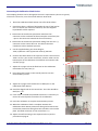
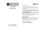
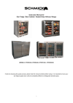
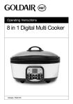
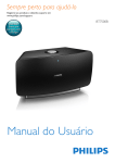
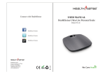
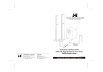
AS600 Calibration Device
USER MANUAL
Cerulean
Rockingham Drive, Linford Wood East, Milton Keynes MK14 6LY, England
Telephone: +44 (0) 1908 233 833 Fax: +44 (0) 1908 235 333
REVISION CONTROL
Revision
Date
Changes made
Author
V1.1
Oct 2012
New manual
JC
V1.2
Dec 2012
Updated address
JC
V1.3
Mar 2014
Rebranded
BSW
V1.4
Jan. 2015
Update
BSW
Manual Scope
User Manuals are provided to give information on how to configure the instrument, calibrate, load and run
samples, and obtain results from the instrument.
Further Assistance
Cerulean can provide training courses on more in-depth technical knowledge, fault finding, diagnostics, and
maintenance and on the instrument. For these options, please contact your regional Cerulean Sales or Service
Manager.
Cerulean also offer a comprehensive installation, spares, repairs, breakdown service, annual maintenance and
contract service. For these options, please contact your regional Cerulean Sales or Service Manager.
For further technical support of the instrument contact [email protected], or your regional
Cerulean office.
Commissioning
It is recommended that the customer carry out a risk assessment on the Air Sampler Calibration Check device
before first use.
Specification
For the specification of the Air Sampler Calibration Check Device please refer to the datasheet available from your
regional Cerulean Sales Manager, Cerulean office, or via the Cerulean Web Site
www.cerulean.com
Page 2 of 9
Air Sampler Calibration Check Device User Manual Stock Code 99932 v1.4 Jan. 2015
CONTENTS
Revision Control............................................................................................................................................................2
Contents .......................................................................................................................................................................3
Safety ............................................................................................................................................................................4
Warnings ...................................................................................................................................................................4
Cautions ....................................................................................................................................................................4
Introduction ..................................................................................................................................................................5
Start Up .........................................................................................................................................................................6
User Interface ...........................................................................................................................................................6
Status ........................................................................................................................................................................6
Calibration Check ..........................................................................................................................................................6
Flow Rate Setting ......................................................................................................................................................6
Connecting the Calibration Check Device .................................................................................................................7
User Maintenance - Requirements ..............................................................................................................................8
Before Sampling Maintenance..................................................................................................................................8
Contacting Cerulean .....................................................................................................................................................9
Air Sampler Calibration Check Device User Manual Stock Code 99932 v1.4 Jan. 2015
Page 3 of 9
SAFETY
While every effort is made to ensure that this product can be operated safely, it is important that reasonable
precautions are taken. In particular, only Cerulean trained personnel should operate this equipment.
Warnings — avoid injury to personnel
Take care when moving this Air Sampler Calibration Check Device.
The Air Sampler Calibration Check Device contains fluid, take care not to spill the fluid.
Cautions — avoid damage to equipment
It is recommended that when adjusting the airflow the unit is left for 5 minutes for the
airflow to stabilise.
European Community (EC) Directive Statement
When this equipment is installed in accordance with the instructions, it will conform to the protection
requirements of the appropriate European regulations. At the time of manufacture the equipment complied with
all the appropriate regulations. Cerulean is not responsible for any interference caused by other cables and
connectors that are not specified, or by any changes or modifications to the equipment. This is not a declaration
of conformity. A copy of the Declaration of Conformity is available from Cerulean on request.
When this product has reached the end of its life it must be disposed of in accordance with local
regulations. Please contact your local agent for further information.
Copyright © Cerulean 2015
No part of this publication may be reproduced, stored in a retrieval system or transmitted, in any form, or by any
means, electronic, mechanical, photocopying, recording or otherwise, without the prior written permission of
Cerulean. The information in this publication is furnished for information purposes only, is subject to change
without notice and should not be construed as a commitment by Cerulean. All information in this document was
believed to be correct at the time of printing but Cerulean assumes no responsibility or liability for any errors or
inaccuracies.
Page 4 of 9
Air Sampler Calibration Check Device User Manual Stock Code 99932 v1.4 Jan. 2015
INTRODUCTION
The Air Sampler Calibration Check Device is designed to check the calibration of the Air Sampler AS600.
At the heart of the Air Sampler is a flowmeter that uses a differential pressure orifice plate. As air flows through
the orifice plate, it creates a pressure differential between the two faces of the plate. The difference in pressure is
dependent upon the flow rate, and thus accurate measurement of this pressure differential determines the flow
rate.
The pressure differential is detected by two pressure transducers located in the instrument box of the Air
Sampler. They are attached to the orifice plate by two translucent pneumatic tubes.
The Air Sampler Calibration Check Device operates by applying the same pressure to one of the pressure
transducers (the other being left open to atmosphere) and the manometer in the calibration check device.
Readings are taken from the Air Sampler and the Calibration Check Device. The gauge of the manometer is
converted to a flow rate so that it can be easily compared to the Air Sampler. If the readings of the Air Sampler
and the Calibration Check Device are less that 2%, the accuracy of the Air Sampler is confirmed to be within
tolerance.
The manometer within the Calibration Check Device is calibrated against a UKAS standard precision pressure
gauge before shipment. It should not need recalibrating but Cerulean are able to offer a calibration service if
required for regulatory purposes.
Air Sampler Calibration Check Device User Manual Stock Code 99932 v1.4 Jan. 2015
Page 5 of 9
START UP
For further details on how to operate the Air Sampler, please refer to the User Manual.
The Air Sampler is designed to be mobile and can be moved to any location easily on the built-in wheels. It is
necessary to ensure that the wheel brakes are applied to prevent the unit moving when sampling.
User Interface
The Air Sampler is fitted with a control panel which includes a display (1), a green button (2), a red button (3) and
a variable controller dial (4).
5
1
4
3
2
Control panel
The display is used to set the airflow (5), set the desired sample duration, and as a time counter.
Status
During sampling the display shows a counter clock which indicated the sampling duration. The sampling period
can be interrupted at any time by pressing the red button. If the sampling period is interrupted, it is
recommended that a new filter be installed and a new sampling period initiated.
CALIBRATION CHECK
Before using the Calibration Check Device it is necessary to reduce the airflow on the Air Sampler to 0 l/min.
Flow Rate Setting
When the unit has been connected to power and the warm-up routine has been carried out (approximately 20
seconds) the unit can be set according to the user’s requirements.
1. Open the display cover.
2. Using the Flow Speed dial (1), reduce the flow speed (2) to 0 l/min. The fan should now be stopped.
2
1
Control panel
3. Press the red button to stop the device.
Page 6 of 9
Air Sampler Calibration Check Device User Manual Stock Code 99932 v1.4 Jan. 2015
Connecting the Calibration Check Device
The sampling duration can be changed to the user’s requirements (4 hours is typical):
If the unit is turned on, turn the unit off and wait 30 seconds.
1. Place the Calibration Check Device onto a flat level surface.
2. Check that there is sufficient fluid within the unit (if the level at
rest is at 0 l/min the volume is sufficient). Use the supplied
liquid bottle to fill if required.
3. Disconnect the translucent pneumatic tube from the +
connector on the underside of the Air Sampler control box (the
+ port is the connector towards the front of the box).
4. Disconnect the translucent pneumatic tubing from the rear (-)
connector on the control box too. This allows the other
transducer to be at ambient pressure.
5. Cut the supplied tubing into three lengths:
Tube (1) 600 mm. Tube (2) 370 mm Tube (3) 180 mm
1
6. Connect the three tubes to the T-piece as shown. Then connect
Tube 1 to the + port on the control box, connect Tube 2 to the
bottom port on the calibration check device and connect tube
3 to the syringe.
2
3
7. Adjust the syringe so that the fluid level on the Calibration
Check Device is at 0 l/min (1).
8. Press the green button on the control panel to start the
measurement process.
1
9. Adjust the syringe so the fluid level is at 500 l/min on the
Calibration Check Device.
10. Check the digital vale on the control box. The value should be
500 l/min + 2%
1
11. If the value is outside the specified tolerance it is necessary to
return the control panel to Cerulean for recalibration.
12. Press the red button to stop the measurement process.
13. When the calibration check is complete. Remove the
Calibration Check Device pneumatic tubing and reconnect the
translucent pneumatic tubing from the controller to the orifice
plate. (Forward connector on the control box is +).
14. Adjust the airflow setting to the required value as per the
procedure on page 6.
Air Sampler Calibration Check Device User Manual Stock Code 99932 v1.4 Jan. 2015
Page 7 of 9
USER MAINTENANCE - REQUIREMENTS
The only necessary maintenance required on the Calibration Check Device is to maintain the correct fluid level
within the manometer tube.
To add more fluid to the device, use the supplied manometer fluid and
add to the manometer via the supplied tubing.
When not in use, connect the tube as shown to prevent evaporation or
spillage of the fluid from the device.
Before Sampling Maintenance
Ensure that there is sufficient volume of fluid within the Calibration Check Device manometer for the
measurement. If, at rest, the fluid is at zero flow, the volume will be sufficient to measure 500 l/min.
Cerulean can offer a calibration service for checking the Calibration Check Device manometer. See the
Contacting Cerulean page for more details on how to arrange this service requirement.
Page 8 of 9
Air Sampler Calibration Check Device User Manual Stock Code 99932 v1.4 Jan. 2015
CONTACTING CERULEAN
Brazil
Cerulean
Molins Do Brasil Máquinas Automáticas Ltda
R. João Lunardelli, 810 CIC
CEP 81450-120 Curitiba
Paraná
Brazil
Phone: +55 41 3227 8300
Fax: +55 41 3227 8310
India
Cerulean
No 1 Jeevan Building Annex
West Park Road
Kumara Park East
Bangalore 560 001
India
Phone: +91 80 2237 2446
Fax: +91 80 2237 2394
P. R. China
Cerulean Shanghai Co. Ltd
Unit 2011 - 2012 Commerce Spirit
No. 1258 Yu Yuan Road
Shanghai 200050
P. R. China
Phone: +86 21 6125 3288
Fax: +86 21 6384 2262
United Kingdom
Cerulean
Rockingham Drive
Linford Wood East
Milton Keynes
MK14 6LY
United Kingdom
Phone: +44 1 908 233 833
Fax: +44 1 908 235 333
Singapore
Cerulean
Molins Far East Pte Ltd
No. 5 Pereira Road
#05-04 Asiawide Building
Singapore
Phone: +65 6289 3788 ext 108
Fax: +65 6289 5788
USA
Cerulean
1470 East Parham Road
Henrico
Virginia 23228
USA
Phone: +1 804 887 2525
Fax: +1 804 887 2526
Air Sampler Calibration Check Device User Manual Stock Code 99932 v1.4 Jan. 2015
Page 9 of 9