1
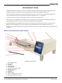
USER MANUAL
Laboratory Carton Tester
Cerulean
Rockingham Drive, Linford Wood East, Milton Keynes MK14 6LY, England
Telephone +44 (0) 1908 233 833 Fax: +44 (0) 1908 235 333
Revision Control
Revision
v1.0
v1.1
v1.3
v2.0
Date
Oct 2012
Dec 2012
Apr 2013
May 2013
Changes made
Author
New manual
JC
Updated address
JC
New format
BSW
Modified Sample Align- BSW
ment diagram
Manual Scope
User Manuals are provided to give information on how to configure the instrument, calibrate, load and run samples,
and obtain results from the instrument.
Further Assistance
Cerulean can provide training courses on more in-depth technical knowledge, fault finding, diagnostics, and maintenance and on the instrument. For these options, please contact your regional Cerulean Sales or Service Manager.
Cerulean also offer a comprehensive installation, spares, repairs, breakdown service, annual maintenance and contract service. For these options, please contact your regional Cerulean Sales or Service Manager.
For further technical support of the instrument contact [email protected], or your regional Cerulean
office.
Commissioning
It is recommended that the customer performs a risk assessment on the LCT before first use.
Specification
For the specification of the Newton Laboratory Carton Tester (LCT) please refer to the datasheet available from your
regional Cerulean Sales Manager, Cerulean office, or via the Cerulean Web Site
www.cerulean.com
Copyright © Cerulean 2013
No part of this publication may be reproduced, stored in a retrieval system or transmitted, in any form, or by any
means, electronic, mechanical, photocopying, recording or otherwise, without the prior written permission of Cerulean. The information in this publication is furnished for information purposes only, is subject to change without
notice and should not be construed as a commitment by Cerulean. All information in this document was believed to
be correct at the time of printing but Cerulean assumes no responsibility or liability for any errors or inaccuracies.
Page 2 of 40
LCT User Manual Stock Code 99936 v2.0 May 2013
CONTENTS
Contents
Safety
Introduction
Parts of the Laboratory Carton Tester
Installation
Software Installation
Installation
Start Up
Adjusting the Pressure Plate Height
Calibration
Zero Cal
Range Cal
Specification Setup
Operation
Pre-Sampling Checks
Test Setup
Box Forming / Crease Strength
Friction Testing
Data Analysis
Operator Mode
Stand-Alone Operation
Calibration Check
Calibration Procedure
Parameter Change
Run
Display Info
Display More Info
Data Collection
Advanced Functions
Application Setup
Engineering
Diagnostics
User Maintenance- Requirements
Weekly Maintenance
Annual Maintenance
Contacting Cerulean
LCT User Manual Stock Code 99936 v2.0 May 2013
3
4
5
5
6
8
8
9
9
11
11
12
14
16
16
16
17
20
23
29
30
30
31
32
34
34
35
36
37
37
38
38
39
39
39
40
Page 3 of 40
SAFE T Y
While every effort is made to ensure that this product can be operated safely, it is important that reasonable precautions are taken. In particular, only Cerulean trained personnel should operate this equipment.
Warnings - Warnings must be strictly obeyed: Failure to do so may cause injury to
personnel and damage to equipment.
Warning: The instrument weights 25 kg so should be lifted by two people when moving.
Warning: Disconnect voltage supplies before performing any maintenance procedures.
Cautions - Cautions must be strictly obeyed: Failure to do so may result in damage
to the equipment or incorrect results.
The unit is to be installed on a firm flat surface away from draughts and vibration.
Only hold the unit by the base as damage could occur if lifted by the pressure plate.
When using the friction tester, keep the device out of direct sunlight as it could affect the
results due to the optical sensor detection device.
Page 4 of 40
LCT User Manual Stock Code 99936 v2.0 May 2013
IN T R ODUC T ION
The Newton Laboratory Carton Tester (LCT) combines crease strength, box forming force, spring back force
and friction tests in one instrument. This eliminates the need for three separate instruments.
The LCT uniquely measures the torque required to bend a crease or form a box providing an instantaneous
curve showing the torque for every degree of rotation (displayed on PC – not supplied).
The device can be used either in stand-alone mode or it can be connected to a PC.
Data is stored in one database on an attached PC (not included) where results can be analysed and aid in setting up packing machinery to ensure cartons are manufactured to specification.
An optional addition to the Newton Carton Tester is the friction tester which allows the user to measure the
angle at which the slippage occurs. The tangent of this angle equals the static coefficient of friction (μ).
The device has a pressure plate which measures the force exerted on to it by the carton as the carton is bent by
the device.
Parts of the Laboratory Carton Tester
Laboratory Carton Tester
1.
2.
3.
4.
5.
6.
7.
8.
9.
10.
11.
12.
Quick release clamp
Clamp plate
Lift plate
Pressure plate
Adjustable feet
Pressure plate height adjust
Keypad (4 buttons)
On/Off Switch
Guide Bar
Display (LCD)
Power, interface and 1.3 A fuse
Small clamp plate and screws
LCT User Manual Stock Code 99936 v2.0 May 2013
Page 5 of 40
IN ST ALLAT ION
The unit must only be lifted by the base plate; any unnecessary force onto the pressure plate
could damage the force cells beyond repair.
1.
Place the instrument onto a solid, vibration free surface. The Newton Carton Tester is a sensitive unit and
will record any vibrations.
2.
Adjust the feet (1) of the legs on the instrument so that the instrument is completely horizontal. Check
using the built-in level gauge (2).
Adjustable Foot
3.
Connect the output from the 24 V transformer to the socket on the rear panel (1).
4.
If connection to an external PC is required, connect the USB lead to the USB socket (2) on the rear panel
and connect the other end of the USB cable to a USB socket on the PC.
5.
If an external PC is to be used, switch on the PC and install the PC software See "Software Installation" on
page 8.
6.
Switch on the LCT using the switch on the front panel.
Page 6 of 40
LCT User Manual Stock Code 99936 v2.0 May 2013
7.
The unit will initialise and the display will show the device name and software version.
8.
If the PC is not connected and the instrument is set to Minimum mode, the unit will go into the Stand-Alone
mode after a few seconds and show the home screen See "Stand-Alone Operation" on page 30.
9.
If the PC is not connected and the instrument is set to Extended mode, the unit will go into the Stand-Alone
mode after a few seconds and show the home screen See "Stand-Alone Operation" on page 30.
10. If the PC is connected, the USB detected screen will be shown See "Calibration" on page 11.
11. It will be necessary to perform a calibration check before using the instrument after unpacking to ensure
that the calibration of the instrument has not been affected during transportation/moving of the unit.
LCT User Manual Stock Code 99936 v2.0 May 2013
Page 7 of 40
SOFT WAR E IN ST ALLAT ION
To utilise the full functionality of the LCT, connect the LCT to a laptop or PC.
For specification requirements, please refer to the data sheet.
Installation
The LCT is supplied with a memory stick that contains all the necessary software and drivers.
1.
Insert the DVD into the PC that will be used with the LCT .
2.
Double-click setup.exe
3.
Follow the onscreen instructions to install the PC user interface.
4.
When complete, connect the LCT to the PC via the supplied USB lead.
5.
Switch on the LCT device.
Windows will detect new hardware.
The installation is now complete.
The software can be found in the Start menu under the name Cerulean Newton CT.
Note For Windows XP: If during the install, you are prompted to download .Net
Framework, accept and follow the onscreen instructions to download the software. This operation will require an Internet connection.
Page 8 of 40
LCT User Manual Stock Code 99936 v2.0 May 2013
ST AR T UP
The Newton Laboratory Carton Tester has been designed to be easy to operate. The parameter settings (angle and
hold duration) are stored in the internal memory so if the unit is turned off it will store the settings for use at a later
date.
Adjusting the Pressure Plate Height
Before using the instrument it is necessary to set the pressure plate height.
Parts of the Folding Mechanism
1.
2.
3.
4.
Lift Plate
Pressure plate
Height adjuster locking mechanism
Height adjuster
To set the height:
1.
Make sure that the instrument is switched on.
2.
On the Engineering screen, select Set zero.
3.
Measure the thickness of the card that is to be tested (e.g. 6 mm).
4.
Unlock the height adjuster locking mechanisms (3).
5.
Use the height adjusters (4) to set the position of the pressure plate to 1/3 to 1/2 (e.g. 2 mm to 3 mm) of
the card thickness below the Lift Plate. Measure the difference in height between the pressure plate and the
lift plate with the digital height gauge.
6.
Check that the height of the pressure plate is the same at both ends.
7.
Lock the height adjuster locking mechanisms (3).
LCT User Manual Stock Code 99936 v2.0 May 2013
Page 9 of 40
Page 10 of 40
LCT User Manual Stock Code 99936 v2.0 May 2013
C ALIBR AT ION
It is always recommended to check the calibration of the Newton Laboratory Carton Tester if the unit has been
moved.
When the PC user interface initially starts, the screen will display the Calibration tab. If, when the pressure plate is
empty, the display does not show 0.0000 ± 0.0002, then a Tare is required.
Zero Cal
1.
Select the Calibration tab.
2.
Select Zero Cal.
3.
Make sure that the pressure plate is empty and select OK.
4.
The display should show 0.0000 ±0.0002. If the display does not show this value, check there is no vibration to the LCT, ensure that the pressure plate is truly empty and repeat the tare procedure.
Note: Because of the sensitivity of the instrument, it is normal for the reading
to flicker as a result of vibration and drafts.
LCT User Manual Stock Code 99936 v2.0 May 2013
Page 11 of 40
Range Cal
1.
Select the Calibration tab.
2.
Before performing a calibration, it is important to ensure that the tare is correct. The display should show
0.0000 ± 0.000 If it doesn't, zero the calibration again.
3.
Select Range Cal.
4.
Place the supplied 500 g weight onto the LCT. Make sure that the weight is located into the centre hole of
the pressure plate.
5.
Select OK to continue.
Page 12 of 40
LCT User Manual Stock Code 99936 v2.0 May 2013
6.
The display should now show a value of 0.5000 ± 0.0002
Note: Because of the sensitivity of the instrument, it is normal for the reading
to flicker as a result of vibration and drafts.
7.
Remove the weight.
LCT User Manual Stock Code 99936 v2.0 May 2013
Page 13 of 40
SP E C IFIC AT ION SE T UP
The Specification Setup screen enables the user to create carton types and add specification limits to specific creases
and friction limits. This allows pass/fail criteria to be applied to suppliers for future evaluation.
Specification Setup tab
Create a New Carton Type
1.
In the Carton Type area of the screen, select New.
2.
Using the Carton Type menu, enter a name for the carton type or select an existing carton type.
3.
Using the Units menu, select the required units.
Torque - Will display results for Torque in N/m.
Torque per meter - Defines the measurement depending upon the length of the crease. Results are displayed
in N/m per m. This allows a user to obtain results that are independent of the crease length to allow results
taken from different cartons to be compared.
4.
If a drawing or photograph has been created for the new carton type, select File and select the required file
from the location where the file has been stored.
Note: To show the drawing or photograph of the carton, select Display.
Note: Depending on the file type, a new viewer may need to be installed.
5.
If a Friction test is to be performed on the selected carton type, enter Min and Max Friction values (if
known).
6.
When the parameters have been entered for the new carton type, select Save to add the new carton type
to the database.
Delete a Carton Type
1.
Using the Carton Type menu, select the carton type that is to be deleted.
2.
In the Carton Type area, select Delete.
Create a Crease Specification
1.
In the Crease Specification area either select a crease name from the menu or enter a new name.
Page 14 of 40
LCT User Manual Stock Code 99936 v2.0 May 2013
Note: Do not use names for carton types that have been previously deleted,
unless the specification is the same as the original.
2.
If the units have been set to Torque per metre, enter the crease length.
3.
Enter Peak Torque values, Peak Torque angle values and Spring Back Force.
Note: Unless the Peak Torque, Peak Torque Angle and Spring Back limits are
known, they can be entered after a test has been done and the results have
been analysed.
4.
To enter a new crease specification, select New and repeat the previous steps.
5.
When all of the Crease Specifications have been entered select Save to add the Crease Specifications to the
database.
Delete a Crease Specification
1.
Using the Crease Specification menu select the crease specification that is to de deleted.
2.
In the Crease Specification area select Delete.
LCT User Manual Stock Code 99936 v2.0 May 2013
Page 15 of 40
OP E R AT ION
The Newton Laboratory Carton Tester can be used to measure the following:
n
n
n
n
Box forming force
Crease strength
Spring back force
Static Coefficient of friction
Box forming and crease strength are performed in a similar way by using different clamping methods. The spring
back force test is performed after the box forming or crease strength test.
The friction test requires an additional part (optional extra) and is used to test the friction properties of material.
Pre-Sampling Checks
1.
Make sure that when the pressure plate is empty the display shows a value of 0.0000. If the zero value is
not correct it will affect the results obtained from the LCT. Follow the Zero Cal procedure to Tare the pressure plate.
2.
Make sure that the pressure plate is adjusted according to the samples being measured. Failure to do so
could cause damage to the force cells located within the LCT.
Test Setup
The Test Setup screen allows users to enter details of the sample that is to be tested, display a drawing of the sample, download data from the LCT print data and run a test.
The controls on the Test Setup screen are as follows:
Test Setup tab
1.
Tabs – Select to display different functions of the user interface.
2.
Print Data – Allows printing of a range of test results.
Page 16 of 40
LCT User Manual Stock Code 99936 v2.0 May 2013
3.
Instrument Data – Indicates the number of results stored within the internal memory of the LCT when
used as a stand-alone device. These can be exported to the PC database or deleted from the LCT.
4.
Connect – Select to enable communication between the PC and LCT.
5.
Indicator – Green indicates that the PC is communicating with the LCT. Red indicates no communication
to the PC.
6.
Help – Select to display the on-line help.
7.
Display Drawing - Select to display a drawing or picture of the carton.
8.
Test – Specifies the test to be performed, Max. Angle and Relax Time at the target angle.
9.
Run Test – Select to start the test that has been specified.
10. Identifier – Allows the user to enter the details of the sample being tested.
Box Forming / Crease Strength
1.
Enter the details of the test into the identifying fields. To create new selectable parameters see the Specification Setup section on page 14
2.
If a spring back force is required, enter a value for the Relax Time (typically 2 Seconds).
3.
Set the height of the pressure plate as described on page 9
4.
Place the sample onto the LCT and set the guide bar (1) at the rear of the machine to align the crease of the
sample between the pressure plate and the lift plate.
LCT User Manual Stock Code 99936 v2.0 May 2013
Page 17 of 40
1- Carton
3 - Pressure Plate
2 - Crease
4 - Lift Plate
5.
Select the appropriate clamp bar to suit the carton size.
6.
Place the selected clamp bar onto/into the sample and clamp the bar into place using the carton clamps (2)
or thumbscrews .
7.
Select Run Test on the user interface.
The LCT will begin the test. The lift plate will start to lift the sample causing the sample to bend along the
crease formation.
During the test, the user interface will display the Live View tab and the torque curve will be displayed.
Page 18 of 40
LCT User Manual Stock Code 99936 v2.0 May 2013
At the end of the lift sequence and if a relax time has been specified, the relax time will also be displayed
after the red line on the graph.
LCT User Manual Stock Code 99936 v2.0 May 2013
Page 19 of 40
Friction Testing
The friction tester is an optional extra for the LCT that measures the friction between two card samples. Usually
outer surface to outer surface.
When using the friction tester, keep the device out of direct sunlight as it could affect the
results due to the optical sensor detection device.
1.
Remove the clamp bar from the LCT.
2.
Locate the two dowel pins (1) on the friction tester into the holes on the LCT (2).
3.
Tighten the thumb screw (3) to secure the friction tester to the lift plate.
4.
Connect the plug (4) from the friction tester to the LCT. Make sure the alignment is correct to prevent damage to the pins.
5.
Place the first sample on the friction tester so that the outer surface is facing up and secure in place with the
spring-loaded retainer (5).
Page 20 of 40
LCT User Manual Stock Code 99936 v2.0 May 2013
6.
Place the second sample on top of the first sample so that the outer surface is facing down.
7.
Place the friction sledge onto the back of the second sample. Ensure that the tongue is facing the friction
sensor and that it is pushed fully back.
8.
Select the Friction tab on the PC user interface.
9.
Enter the identifier details for the sample.
LCT User Manual Stock Code 99936 v2.0 May 2013
Page 21 of 40
Note: The status indicator shows the status of the friction tester. Red = Friction device not connected. Yellow = Sled not in position. Green = Ready to test.
10. Select Run Test.
The lift plate will lift until the friction sledge slides along the sample. When the test has finished, the lift plate
will return to the home position and the user interface will display the results for the test.
Page 22 of 40
LCT User Manual Stock Code 99936 v2.0 May 2013
Data Analysis
Using the Data Analysis screen it is possible to review previous test results and import test data that has been measured on another LCT.
1.
Select the Data Analysis tab.
Crease Performance Curve - via MS Excel
1.
In the Data Analysis screen, select Crease Performance Curve.
The Crease Performance Curve form will be displayed in an Excel tab.
2.
Select the Carton type.
3.
Select the Crease type.
4.
Select any other filter options required.
5.
Select Get Tests.
The selected tests will be displayed.
6.
Enable the appropriate check boxes in the Plot column for the results that are to be viewed.
7.
Select Plot Curves.
The selected results will be displayed in a graph format.
LCT User Manual Stock Code 99936 v2.0 May 2013
Page 23 of 40
Note: To display the value of a point on a curve, hover the cursor on a point on
the graph. To display test information, click on a curve.
Spring Back Performance Curve - via MS Excel
1.
In the Data Analysis screen, select Spring Back Performance Curve.
The Spring Back Performance Curve form will be displayed in an Excel tab.
2.
Select the Carton type.
3.
Select the Crease type.
4.
Select any other filter options required.
5.
Select Get Tests.
The selected tests will be displayed.
6.
Enable the appropriate check boxes in the Plot column for the results that are to be viewed.
7.
Select Plot Curves.
The selected results will be displayed in a graph format.
Page 24 of 40
LCT User Manual Stock Code 99936 v2.0 May 2013
Peak Torque - via MS Excel
1.
In the Data Analysis screen, select Peak Torque.
The Peak Torque form will be displayed in an Excel tab.
2.
Select the Carton type.
3.
Select the Crease type.
4.
Select any other filter options required.
5.
Select Get Data.
Results will be displayed in a graph format.
Friction - via MS Excel
1.
In the Data Analysis screen, select Friction.
The Friction form will be displayed in an Excel tab.
2.
Select the Carton type.
3.
Select the Crease type.
4.
Select any other filter options required.
LCT User Manual Stock Code 99936 v2.0 May 2013
Page 25 of 40
5.
Select Get Data.
Results will be displayed in a graph format.
Peak Torque Angle - via MS Excel
1.
In the Data Analysis screen, select Peak Torque Angle.
The Friction form will be displayed in an Excel tab.
2.
Select the Carton type.
3.
Select the Crease type.
4.
Select any other filter options required.
5.
Select Get Tests.
Results will be displayed in a graph format.
Page 26 of 40
LCT User Manual Stock Code 99936 v2.0 May 2013
Spring Back Force - via MS Excel
1.
In the Data Analysis screen, select Spring Back Force.
The Spring Back Force form will be displayed in an Excel tab.
2.
Select the Carton type.
3.
Select the Crease type.
4.
Select any other filter options required.
5.
Select Get Data.
Results will be displayed in a graph format.
Supplier Performance - via MS Excel
1.
In the Data Analysis screen, select Supplier Performance.
The Supplier Performance form will be displayed in an Excel tab.
2.
Select Supplier.
3.
Select Get Data.
4.
Results will be displayed below.
LCT User Manual Stock Code 99936 v2.0 May 2013
Page 27 of 40
Import Data
Import data as follows:
1. In the Data Analysis screen, select Import Data.
A Browse dialog box will be displayed.
2.
Browse to the required folder.
3.
Select Open.
When the Data has been imported a summary screen will be displayed.
4.
Select OK.
Page 28 of 40
LCT User Manual Stock Code 99936 v2.0 May 2013
OP E R AT OR M ODE
The Operator mode provides a restricted interface that allows the user to select a Carton type a Crease ID and display
a drawing of the selected carton. When the carton type and the crease have been selected a test can be run.
Select the Operator mode
1.
To select the Operator mode, simultaneously press the Alt key and the X key.
A confirmation dialog box will be displayed.
2.
Select OK.
The Operator Mode screen will be displayed.
Exit from the Operator mode
1.
To exit from the Operator mode, simultaneously press the Alt key and the X key.
2.
Enter the password and select OK.
LCT User Manual Stock Code 99936 v2.0 May 2013
Page 29 of 40
ST AN D-ALON E OP E R AT ION
The LCT can also be used as a stand-alone item without using an attached PC.
Calibration Check
1.
Switch the unit on and wait for the start-up screen to clear.
2.
Make sure there is nothing on the pressure plate.
3.
Check the display reads zero.
4.
Place the supplied 500 g weight onto the LCT. Ensure that the weight is located into the centre hole of the
pressure plate.
5.
The display should show 0.500 ± 0.0002
6.
If the result is incorrect, refer to the Calibration Procedure See "Calibration Procedure" on page 31.
Page 30 of 40
LCT User Manual Stock Code 99936 v2.0 May 2013
Calibration Procedure
If the calibration check indicates that the calibration is not correct, follow the procedure below to recalibrate the
instrument.
Note: Full Range Calibration can only be performed if the unit has been set to
operate in the Extended mode.
See "Application Setup" on page 37
1.
With the instrument turned on select the Cal button.
2.
Select 1 (Zero Cal.) to tare the instrument.
3.
Ensure that the pressure plate is empty and press and hold Run until the unit beeps. The instrument will
perform a tare function.
4.
Select Backto exit.
5.
Select 2 (Range Cal.) to perform a Range Calibration
6.
The display will show the following screen.
LCT User Manual Stock Code 99936 v2.0 May 2013
Page 31 of 40
7.
Place the 500 g weight standard onto the pressure plate by locating it in the central hole.
8.
The display will show the Torque value.
9.
Select and hold Run until the unit beeps to start the calibration function.
10. The display will show the new torque value and the Scaling factor (SF) for the new calibration.
11. Select and hold Accept until the unit beeps to accept the new calibration.
12. Select Back to return to the previous screen and then select Back to return to the home screen ready for
use.
Parameter Change
The two parameters which can be changed when the unit is used as a stand-alone device are:
Page 32 of 40
LCT User Manual Stock Code 99936 v2.0 May 2013
l
l
Angle of crease (from 0 o to 115 o)
Relax time period (from 0 seconds to 15 seconds)
To change these parameters:
1.
From the home screen press the Cal button.
2.
Press the 3 button to enter the Set & misc functions.
3.
Press the 1 button to enter the settings screen
4.
The cursor will flash on the parameter that can be changed.
5.
Use the Inc button to increase the value, or Dec to decrease the value.
6.
NxtP moves the cursor to the next parameter to allow a change of the value.
7.
When the parameters have been set to the required values, press the Done button to exit. The display will
return to the home screen.
LCT User Manual Stock Code 99936 v2.0 May 2013
Page 33 of 40
Run
1.
With the unit switched on and calibrated and the sample clamped in position, select the Run button.
2.
Select Run.
The sample will be measures and the result will be displayed.
3.
Select Next to return to the home screen.
Note: After 250 tests have been performed, a message will be displayed that
asks the user to either transfer the test results to a PC and clear the units
built-in memory or overwrite previously saved test results.
Note: Test results can be transferred at any time using the Test Setup tab See
"Test Setup" on page 16.
Note: Test results should be downloaded before changing either the carton or
the crease type.
Display Info
1.
With the instrument switched on, select the Cal button.
2.
Select 3 to show Set & misc
Page 34 of 40
LCT User Manual Stock Code 99936 v2.0 May 2013
3.
Select 2 to show Info.
4.
Select View to show the tests.
Note: If the memory is empty, the View function is not available.
5.
Use the arrow keys to select the required test .
6.
Select Back twice to display the home screen
Display More Info
Note: The More Info screen contains information that can be used for diagnostic purposes.
1.
With the instrument switched on, select the Cal button.
2.
Select 3 to show the Set & misc screen.
LCT User Manual Stock Code 99936 v2.0 May 2013
Page 35 of 40
3.
Select 2 to show Info.
4.
Select More to show the more info screen.
5.
Select Home to show the Home screen.
Data Collection
Data can be transferred from the LCT to the PC by selecting Collect Data on the Test Setup screen.
After data has been transferred from the LCT to the PC and you have checked that the data has been transferred successfully, select Erase Data to erase the data from the LCT.
Page 36 of 40
LCT User Manual Stock Code 99936 v2.0 May 2013
ADVAN C E D FUN C T ION S
Application Setup
Application Setup
File Locations
The File Locations area allows the user to change the path to the MS Excel files and the database.
Settings in this area should only be changed by Cerulean trained engineers.
Change Password
The Default password is "Cerulean"
The Change Password button allows the user to change the password that is used to exit from the Operator mode.
For more information see See "Operator Mode" on page 29.
Instrument Mode
It is possible to restrict the functions available to the user when the LCT is used in a stand-alone mode.
The Instrument Mode menu allows the LCT to be set to either the Minimum mode or the Extended mode when it is
used in stand-alone mode.
l The Minimum mode prevents the user from performing a Range Calibration and restricts the user to performing Zero Calibration, send Table Down and Run tests.
l The Extended mode allows the user to use all functions.
Reset Configuration File
This is password protected and restores the file path names to their default settings.
To reset the file locations back to their original settings select Reset config file.
Field Names
The Field names area allows the user to define which fields are shown on the Test Setup screen.
To display a field enable the appropriate check box.
The last three field names can be redefined by the user.
LCT User Manual Stock Code 99936 v2.0 May 2013
Page 37 of 40
Engineering
This tab displays information about the LCT.
Engineering tab
1.
Machine ID – This is associated to the serial number of the instrument connected to the PC.
2.
Next Test No – Shows the test number of the next test that will take place.
3.
Scale Factor – Internal calibration reference value.
4.
Factory Tare – The value of the tare at manufacture.
5.
Current Tare – The current tare value.
6.
Tare Drift - If this is over 20% different from the factory tare, the force cells could be damaged.
7.
V Sys – Voltage input from the power source.
8.
Overload Limit - Shows the maximum force that the instrument will accept before showing an error. This
protects the instrument from overload.
9.
Instrument Version - Displays the version number of the firmware that is installed on the instrument
LCT.
10. Application Version – Displays the version number of the PC software.
Diagnostics
The buttons at the bottom of the screen allow the Lift Plate (Table ) to be manually controlled for diagnostic purposes.
Table Up – allows manual control of the table.
Table Down - allows manual control of the table.
Set Zero – resets the lift table to check the function of the zero switch.
Resend Data – Not used.
Page 38 of 40
LCT User Manual Stock Code 99936 v2.0 May 2013
USE R M AIN T E N AN C E - R E QUIR E M E N T S
Maintenance should only be performed by Cerulean trained engineers.
Weekly Maintenance
1.
Clean the LCT with a soft cloth. Do not use solvents to clean; polishing spray should be adequate to clean
the device.
2.
Perform a Range Calibration check regularly at least once a week. Recalibrate if necessary.
Note: The instrument performs an auto tare check every time it is switched
on. The pressure plate must be empty at this time.
Annual Maintenance
The LCT is designed to give years of maintenance free use. Damage can be caused by using the LCT in a way not outlined in this manual. The force cells are designed to measure a vertical load applied to the pressure plate. Twisting
and excessive force can damage the force cells.
Cerulean can offer a repair service on the LCT . Contact [email protected] for more details.
LCT User Manual Stock Code 99936 v2.0 May 2013
Page 39 of 40
C ON T AC T IN G C E R ULE AN
Brazil
Cerulean
Molins Do Brasil Máquinas Automáticas
Ltda
R. João Lunardelli, 810 CIC
CEP 81450-120 Curitiba
Paraná
Brazil
Phone: +55 41 3227 8300
Fax: +55 41 3227 8310
PR China
Cerulean Shanghai Co. Ltd
Unit 2011 - 2012 Commerce Spirit
No. 1258 Yu Yuan Road
Shanghai 200050
P. R. China
Phone: +86 21 6125 3288
Fax: +86 21 6384 2262
Germany
Cerulean GmbH
Spitaler Strasse 32
20095 Hamburg
Germany
Phone: +49 40 328 7385-10
Fax: +49 40 328 7385-22
India
Cerulean
No 1 Jeevan Building Annex
West Park Road
Kumara Park East
Bangalore 560 001
India
Phone: +91 80 2237 2446
Fax: +91 80 2237 2394
United Kingdom
Cerulean
Rockingham Drive
Linford Wood East
Milton Keynes
MK14 6LY
United Kingdom
Phone: +44 1 908 233 833
Fax: +44 1 908 235 333
USA
Cerulean
1470 East Parham Road
Henrico
Virginia 23228
USA
Phone: +1 804 887 2525
Fax: +1 804 887 2526
Singapore
Cerulean
Molins Far East Pte Ltd
No. 5 Pereira Road
#05-04 Asiawide Building
Singapore
Phone: +65 6289 3788 ext 108
Fax: +65 6289 5788
Page 40 of 40
LCT User Manual Stock Code 99936 v2.0 May 2013