1
Application Note
V850 Standby Modes
V850ES/SG2
V850ES/SJ2
Document No. U18825EE1V0AN00
Date Published June 2007
© NEC Electronics Corporation June 2007
Printed in Germany
NOTES FOR CMOS DEVICES
1
VOLTAGE APPLICATION WAVEFORM AT INPUT PIN
Waveform distortion due to input noise or a reflected wave may cause malfunction. If the input of the
CMOS device stays in the area between VIL (MAX) and VIH (MIN) due to noise, etc., the device may
malfunction. Take care to prevent chattering noise from entering the device when the input level is fixed,
and also in the transition period when the input level passes through the area between VIL (MAX) and
VIH (MIN).
2
HANDLING OF UNUSED INPUT PINS
Unconnected CMOS device inputs can be cause of malfunction. If an input pin is unconnected, it is
possible that an internal input level may be generated due to noise, etc., causing malfunction. CMOS
devices behave differently than Bipolar or NMOS devices. Input levels of CMOS devices must be fixed
high or low by using pull-up or pull-down circuitry. Each unused pin should be connected to VDD or GND
via a resistor if there is a possibility that it will be an output pin. All handling related to unused pins must
be judged separately for each device and according to related specifications governing the device.
3
PRECAUTION AGAINST ESD
A strong electric field, when exposed to a MOS device, can cause destruction of the gate oxide and
ultimately degrade the device operation. Steps must be taken to stop generation of static electricity as
much as possible, and quickly dissipate it when it has occurred. Environmental control must be
adequate. When it is dry, a humidifier should be used. It is recommended to avoid using insulators that
easily build up static electricity. Semiconductor devices must be stored and transported in an anti-static
container, static shielding bag or conductive material. All test and measurement tools including work
benches and floors should be grounded. The operator should be grounded using a wrist strap.
Semiconductor devices must not be touched with bare hands. Similar precautions need to be taken for
PW boards with mounted semiconductor devices.
4
STATUS BEFORE INITIALIZATION
Power-on does not necessarily define the initial status of a MOS device. Immediately after the power
source is turned ON, devices with reset functions have not yet been initialized. Hence, power-on does
not guarantee output pin levels, I/O settings or contents of registers. A device is not initialized until the
reset signal is received. A reset operation must be executed immediately after power-on for devices
with reset functions.
5
INPUT OF SIGNAL DURING POWER OFF STATE
Do not input signals or an I/O pull-up power supply while the device is not powered. The current
injection that results from input of such a signal or I/O pull-up power supply may cause malfunction and
the abnormal current that passes in the device at this time may cause degradation of internal elements.
Input of signals during the power off state must be judged separately for each device and according to
related specifications governing the device.
All other product, brand, or trade names used in this publication are the trademarks
or registered trademarks of their respective trademark owners.
Product specifications are subject to change without notice. To ensure that you have the latest
product data, please contact your local NEC Electronics sales office.
2
Application Note U18825EE1V0AN00
DISCLAIMER
The related documents in this customer notification may include preliminary versions. However, preliminary versions may not have been marked as such.
The information in this customer notification is current as of its date of publication. The information is subject to
change without notice. For actual design-in, refer to the latest publications of NEC’s data sheets or data books, etc.,
for the most up-to-date specifications of NEC PRODUCT(S). Not all PRODUCT(S) and/or types are available in
every country. Please check with an NEC sales representative for availability and additional information.
No part of this customer notification may be copied or reproduced in any form or by any means without prior written
consent of NEC. NEC assumes no responsibility for any errors that may appear in this customer
notification. NEC does not assume any liability for infringement of patents, copyrights or other intellectual property
rights of third parties by or arising from the use of NEC PRODUCT(S) listed in this customer
notification or any other liability arising from the use of such PRODUCT(S).
No license, express, implied or otherwise, is granted under any patents, copyrights or other intellectual
property rights of NEC or others. Descriptions of circuits, software and other related information in this
customer notification are provided for illustrative purposes of PRODUCT(S) operation and/or application examples
only. The incorporation of these circuits, software and information in the design of customer’s
equipment shall be done under the full responsibility of customer. NEC assumes no responsibility for any losses
incurred by customers or third parties arising from the use of these circuits, software and information.
While wherever feasible, NEC endeavors to enhance the quality, reliability and safe operation of
PRODUCT(S) the customer agree and acknowledge that the possibility of defects and/or erroneous thereof cannot
be eliminated entirely. To minimize risks of damage to property or injury (including death) to persons arising from
defects and/or errors in PRODUCT(S) the customer must incorporate sufficient safety measures in their design,
such as redundancy, fire-containment and anti-failure features.
The customer agrees to indemnify NEC against and hold NEC harmless from any and all consequences of any and
all claims, suits, actions or demands asserted against NEC made by a third party for damages caused by one or
more of the items listed in the enclosed table of content of this customer notification for PRODUCT(S) supplied
after the date of publication.
Applicable Law:
The law of the Federal Republic of Germany applies to all information provided by NEC to the Customer under this
Operating Precaution document without the possibility of recourse to the Conflicts Law or the law of 5th July 1989
relating to the UN Convention on Contracts for the International Sale of Goods (the Vienna CISG agreement).
Düsseldorf is the court of jurisdiction for all legal disputes arising directly or indirectly from this information. NEC is
also entitled to make a claim against the Customer at his general court of jurisdiction.
If the supplied goods/information are subject to German, European and/or North American export controls, the
Customer shall comply with the relevant export control regulations in the event that the goods are exported and/or
re-exported. If deliveries are exported without payment of duty at the request of the
Customer, the Customer accepts liability for any subsequent customs administration claims with respect to NEC.
Notes: 1.
“NEC” as used in this statement means NEC Electronics Corporation and also includes its direct or
indirect owned or controlled subsidiaries.
2.
“PRODUCT(S)” means ‘NEC semiconductor products’ (NEC semiconductor products means any
semiconductor product developed or manufactured by or for NEC) and/or ‘TOOLS’ (TOOLS means
‘hardware and/or software development tools’ for NEC semiconductor products’
developed, manufactured and supplied by ‘NEC’ and/or ‘hardware and/or software development tools’
supplied by NEC but developed and/or manufactured by independent 3rd Party vendors worldwide as
their own product or on contract from NEC)
Application Note U18825EE1V0AN00
3
For further information,
please contact:
NEC Electronics Corporation
1753, Shimonumabe, Nakahara-ku,
Kawasaki, Kanagawa 211-8668,
Japan
Tel: 044-435-5111
http://www.necel.com/
[America]
[Europe]
[Asia & Oceania]
NEC Electronics America, Inc.
2880 Scott Blvd.
Santa Clara, CA 95050-2554, U.S.A.
Tel: 408-588-6000
800-366-9782
http://www.am.necel.com/
NEC Electronics (Europe) GmbH
Arcadiastrasse 10
40472 Düsseldorf, Germany
Tel: 0211-65030
http://www.eu.necel.com/
NEC Electronics (China) Co., Ltd
7th Floor, Quantum Plaza, No. 27 ZhiChunLu Haidian
District, Beijing 100083, P.R.China
TEL: 010-8235-1155
http://www.cn.necel.com/
Hanover Office
Podbielski Strasse 166 B
30177 Hanover
Tel: 0 511 33 40 2-0
NEC Electronics Shanghai Ltd.
Room 2509-2510, Bank of China Tower,
200 Yincheng Road Central,
Pudong New Area, Shanghai P.R. China P.C:200120
Tel: 021-5888-5400
http://www.cn.necel.com/
Munich Office
Werner-Eckert-Strasse 9
81829 München
Tel: 0 89 92 10 03-0
Stuttgart Office
Industriestrasse 3
70565 Stuttgart
Tel: 0 711 99 01 0-0
United Kingdom Branch
Cygnus House, Sunrise Parkway
Linford Wood, Milton Keynes
MK14 6NP, U.K.
Tel: 01908-691-133
Succursale Française
9, rue Paul Dautier, B.P. 52180
78142 Velizy-Villacoublay Cédex
France
Tel: 01-3067-5800
Sucursal en España
Juan Esplandiu, 15
28007 Madrid, Spain
Tel: 091-504-2787
NEC Electronics Hong Kong Ltd.
12/F., Cityplaza 4,
12 Taikoo Wan Road, Hong Kong
Tel: 2886-9318
http://www.hk.necel.com/
Seoul Branch
11F., Samik Lavied’or Bldg., 720-2,
Yeoksam-Dong, Kangnam-Ku,
Seoul, 135-080, Korea
Tel: 02-558-3737
NEC Electronics Taiwan Ltd.
7F, No. 363 Fu Shing North Road
Taipei, Taiwan, R. O. C.
Tel: 02-8175-9600
NEC Electronics Singapore Pte. Ltd.
238A Thomson Road,
#12-08 Novena Square,
Singapore 307684
Tel: 6253-8311
http://www.sg.necel.com/
Tyskland Filial
Täby Centrum
Entrance S (7th floor)
18322 Täby, Sweden
Tel: 08 638 72 00
Filiale Italiana
Via Fabio Filzi, 25/A
20124 Milano, Italy
Tel: 02-667541
Branch The Netherlands
Steijgerweg 6
5616 HS Eindhoven
The Netherlands
Tel: 040 265 40 10
G06.6-1A
4
Application Note U18825EE1V0AN00
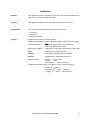
Introduction
Readers
This application note is intented for users who want to understand the functions of the and similar V850 derivatives.
Purpose
This application note presents the hardware application note of the
.
Organization
This system specification describes the following sections:
Legend
•
Overview
•
Operation
•
Software functions
Symbols and notation are used as follows:
Weight in data notation : Left is high-order column, right is low order column
Active low notation
: xxx (pin or signal name is over-scored) or
/xxx (slash before signal name)
Memory map address: : High order at high stage and low order at low stage
Note
: Explanation of (Note) in the text
Caution
: Information requiring particular attention
Remark
: Supplementary explanation to the text
Numeric notation
: Binary . . . XXXX or XXXB
Decimal . . . XXXX
Hexadecimal . . . XXXXH or 0x XXXX
Prefixes representing powers of 2 (address space, memory capacity)
K (kilo) : 210 = 1024
M (mega) : 220 = 10242 = 1,048,576
G (giga) : 230 = 10243 = 1,073,741,824
Application Note U18825EE1V0AN00
5
6
Application Note U18825EE1V0AN00
Table of Contents
Chapter 1
1.1
Chapter 2
2.1
Chapter 3
3.1
3.2
3.3
Overview . . . . . . . . . . . . . . . . . . . . . . . . . . . . . . . . . . . . . . . . . . . . . . . . . . . . . . 9
Standby modes - Overview . . . . . . . . . . . . . . . . . . . . . . . . . . . . . . . . . . . . . . . . . . . . . . . 9
Operation . . . . . . . . . . . . . . . . . . . . . . . . . . . . . . . . . . . . . . . . . . . . . . . . . . . . 11
Function of Standby Modes . . . . . . . . . . . . . . . . . . . . . . . . . . . . . . . . . . . . . . . . . . . . . 11
Software Functions . . . . . . . . . . . . . . . . . . . . . . . . . . . . . . . . . . . . . . . . . . . . 13
Demonstration Software . . . . . . . . . . . . . . . . . . . . . . . . . . . . . . . . . . . . . . . . . . . . . . . . 13
Software Structure . . . . . . . . . . . . . . . . . . . . . . . . . . . . . . . . . . . . . . . . . . . . . . . . . . . . . 13
Demonstration Software Usage . . . . . . . . . . . . . . . . . . . . . . . . . . . . . . . . . . . . . . . . . . 14
Appendix A Reference Documentation . . . . . . . . . . . . . . . . . . . . . . . . . . . . . . . . . . . . . . 17
Appendix B Revision History . . . . . . . . . . . . . . . . . . . . . . . . . . . . . . . . . . . . . . . . . . . . . . . 18
Application Note U18825EE1V0AN00
7
8
Application Note U18825EE1V0AN00
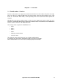
Chapter 1 Overview
1.1 Standby modes - Overview
Several standby modes are supported by V850 microcontrollers in order to reduce the power consumption of the device. In standby modes either the clock or power supply to some functional parts of the
device are switched off. Alternatively a slower operating clock can be selected to reduce power consumption.
Although the usage of the standby modes is similar for most V850 devices please check the user's
manual for the individual device before applying the method to other microcontrollers than V850ES/Sx2
which is used as reference in this application note.
The standby modes supported in V850ES/Sx2 are:
• HALT
• IDLE 1
• IDLE 2
• STOP
• Subclock Operation Mode
• Sub IDLE Mode
This application note shows the general use of V850 standby modes.
As examples the HALT, STOP and Subclock modes are shown in examples.
Other standby modes can be set easily by modifiying the given examples.
Application Note U18825EE1V0AN00
9
Chapter 1
10
Overview
Application Note U18825EE1V0AN00
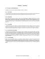
Chapter 2 Operation
2.1 Function of Standby Modes
The general function of the individual standby modes is as follows:
2.1.1 HALT Mode
In HALT Mode the clock supply to the CPU is stopped and therefore no instruction executen takes place
anymore. HALT mode is entered by executing a dedicated assembler instruction ("HALT").
2.1.2 IDLE Modes
IDLE Modes are entered by setting the Power Save Mode Register (PSMR) and Power Save Control
Register (PSC) accordingly. In Idle modes the clock supply to the CPU and to most peripherals is cut
thus reducing the power consumption of the microcontroller. In contrast to IDLE 1 Mode the clock supply to PLL and flash memory are cut additionally in IDLE2 Mode which reduces the power consumption
even more.
2.1.3 STOP Mode
In STOP Mode the main oscillator is stopped and therefore the clock supply to the CPU and most
peripherals is stopped thus reducing the power consumption to a minimum. STOP mode is entered by
setting the Power Save Mode Register (PSMR) and Power Save Control Register (PSC) accordingly.
2.1.4 Subclock Operation Mode
In Subclock Operation Mode the CPU operation clock is switched to the subclock oscillator and therefore the CPU operates instructions at 32.768kHz rather than at the clock frequency of the main oscillator or the PLL output frequency. As execution speed is reduced very much in this mode, the power
consumption is reduced too. In Subclock Operation Mode it is possible to switch off the main oscillator
by software. Subclock Operation Mode is entered by configuring the Processor Clock Control Register
(PCC) accoringly.
2.1.5 Sub-IDLE Mode
When the microcontroller operates in Subclock Operation Mode the power consumption can be
reduced further by entering Sub-IDLE-Mode. When the main clock is switched off in Subclock Operation Mode and then Sub-IDLE Mode is entered the power consumption can be reduced to a level as low
as STOP mode. When waking up from Sub-IDLE Mode the microcontroller enters Subclock Operation
Mode.
Application Note U18825EE1V0AN00
11
Chapter 2
12
Operation
Application Note U18825EE1V0AN00
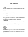
Chapter 3
Software Functions
3.1 Demonstration Software
The demonstration software shows the function of the following standby modes:
- HALT Mode
- STOP Mode
- Subclock Operation Mode
Other operation modes operate very similar to the above and can be implemented by simple modifications of the demonstration software.
3.2 Software Structure
The demonstration software contains the following parts:
• powersave_halt()
This routine is used for entering HALT mode. The HALT mode is entered using the "HALT" instruction
within this routine.
• powersave_stop_prepare()
routine preparing for entering STOP mode. STOP mode is entered by an assembler function
• _powersave_stop
This is an assembler routine which is called by powersave_stop_prepare(). It modifies the Power Save
Mode Register (PSMR) and the Power Save Control Register (PSC).
• _powersave_sub
This routine switches to subclock operation and switches off the main clock afterwards.
• _powersave_main
This routine is used to wake up from subclock mode. First the main clock is re-started and next operation is changed from subclock to main clock operation after the oscillation stabilization time has passed.
To make the demonstration software operate in a complete project some further functions are required.
Although they do not mainly demonstrate the function of the standby modes they are described shortly
below in order to help understand the function of the whole demonstration project.
The further parts of the demonstration software are:
• main()
Contains the basic system initialization, peripheral initialization and selection of the operation mode to
be demonstrated.
• init_ports()
Initialization of microcontroller ports to faciliate analyzation of the operation modes. If the code is run on
the V850ES/SG2 starter kit some data can be output on the 7-segment display and the keys of the
board can be used to wake up the microcontroller from the HALT or STOP mode.
• init_port_cm()
Initialization of the port cm at which the CLKOUT signal can be output to monitor the CPU operation frequency using an oscilloscope.
•
segout()
Application Note U18825EE1V0AN00
13
Chapter 3 Software Functions
Function delivering a code to output a count value for the 7-segment display output. This is used to
show that the microcontroller is active after wake up from the standby mode.
• intp0() and intp1()
Interrupt service routines. The interrupt signals for these routines are used to wakeup the microcontroller from the standby modes. The ISRs themselves are not used in this application.
• INTTP0CC0
Interrupt service routine used for counting in order to show that the device operates correctly after
wakeup from standby mode.
3.3 Demonstration Software Usage
The demonstration software uses #defines to select the standby mode to demonstrate. The user can
select between the following modes:
• mode_normal
• mode_stop
• mode_halt
• mode_subclock
3.3.1 mode_normal
This is the normal operation mode. Here no standby mode is entered. This mode can be used to check
the system operation under normal conditions in order to compare the behaviour with the function if a
standby mode is selected.
3.3.2 mode_stop
If this mode is selected the software will go into STOP mode after program start.
Before going into STOP mode the contents of the interrupt masks for all interrupt sources are backed
up. This method is used to demonstrate how to reduce the number of wakeup sources in the standby
mode. In general the standby mode can be released by any unmasked maskable interrupt (and RESET
and NMI). In the demonstration system also a timer interrupt is running. This timer interrupt should not
wake up the microcontroller from standby mode. Instead only the pin interrupts INTP0 and INTP1 (and
RESET) shall be allowed to wake up the microcontroller. So before entering the standby mode the other
interrupt sources are blocked. After the standby mode is released the original interrupt status is
restored.
The STOP mode is entered using an assembler function. To enter STOP mode first the standby mode
to be entered must be selected using the Power Save Mode Register (PSMR). Next the STOP mode is
entered using the Power Save Control Register (PSC).
After entering a standby mode a sequence of 5 NOP instructions must be entered in the code. This is
also shown in the example. The code execution will stop here. After the standby mode is cancelled (in
this case by executing the INTP0 or INTP1 pin interrupt) program execution will continue from here.
After the STOP mode is released the program execution continues normally. This can be seen from the
timer interrupt continuing to operate and counting up numbers on the 7-Segment display connected to
Port 9 of the V850ES/SG2 starterkit hardware.
3.3.3 mode_halt
If this mode is selected the software will go into HALT mode after program start.
In general the standby mode can be released by any unmasked maskable interrupt (and RESET and
NMI). In the demonstration system also a timer interrupt is running. This timer interrupt should not wake
14
Application Note U18825EE1V0AN00
Chapter 3 Software Functions
up the microcontroller from standby mode. Instead only the pin interrupts INTP0 and INTP1 (and
RESET) shall be allowed to wake up the microcontroller. So before entering the standby mode the other
interrupt sources are blocked. After the standby mode is released the original interrupt status is
restored.
The HALT mode is entered using the assembler instruction “HALT”. After entering a standby mode a
sequence of 5 NOP instructions must be entered in the code. This is also shown in the example. The
code execution will stop here. After the standby mode is cancelled (in this case by executing the INTP0
or INTP1 pin interrupt) program execution will continue from here.
After the HALT mode is released the program execution continues normally. This can be seen from the
timer interrupt continuing to operate and counting up numbers on the 7-Segment display connected to
Port 9 of the V850ES/SG2 starterkit hardware.
3.3.4 mode_subclock
If this mode is selected the software will enter Subclock mode using the assembler function
“_powersave_sub”. In this function the subclock crystal frequency of 32.768kHz is selected as the operation clock for the CPU. A crystal of 32.768kHz must be connected to the XT1 and XT2 pins of the
microcontroller.
Next after the CPU operation has switched to subclock operation the main clock is switched off. This will
reduce the power consumption to a very level. The CPU is now running in subclock mode and executes
its instruction at low speed. A port (P50) is set to detect this point using an oscilloscope.
Next the CPU operation is switched back to main clock operation. This is done in the assembler function “_powersave_main”. First the main clock is started. Here the oscillation stabilization time must pass
before the main clock signal can be used to drive the CPU. In contrast to the startup after a RESET or
STOP mode call where this is done automatically this must be done in a software loop when switching
on the CPU clock supply by software using the PCC register. After the main clock operates properly the
CPU is switched back to operation on main clock. A port (P50) is cleared to detect this point using an
oscilloscope.
Application Note U18825EE1V0AN00
15
Chapter 3 Software Functions
16
Application Note U18825EE1V0AN00
Appendix A
Reference Documentation
Item
Document No.
Document Title
1
U16603EJ
V850ES/SJ2 Hardware (User’s Manual)
2
U16541EJ
V850ES/SG2 Hardware (User’s Manual)
3
U15943EJ
V850ES Architecture (User’s Manual)
Application Note U18825EE1V0AN00
17
Appendix B
Revision History
Item
Date pulished
Document No.
Comment
1
June 2007
U18825EE1V0AN00
New List
18
Application Note U18825EE1V0AN00