1
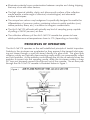
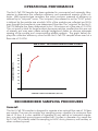
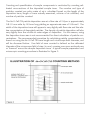
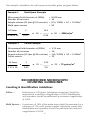
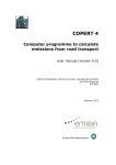
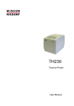
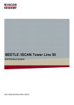
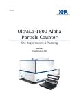
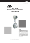
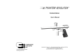
AIR-O-CELL® CSI
Bioaerosol Sampling Cassette
For the collection of viable and non-viable airborne particles
Laboratory
& User Manual
Air-O-Cell® CSI Sampling Cassette
The Air-O-Cell Collector for SEM Identification (CSI) is a unique sampling cassette
specifically designed for the rapid collection and quantitative and elemental analysis
of a wide range of airborne aerosols. With the Air-O-Cell CSI you can use optical
and scanning electron microscopy and x-ray analysis on the exact same air sample.
The Air-O-Cell CSI collects both viable and non-viable particulate such as mold
spores, pollen, insect parts, skin cell fragments, fibers (asbestos, fiberglass, cellulose, etc.) and inorganic particles.
Suggested & potential applications include, but are not limited to, the following:
APPLICATIONS
Indoor Air Quality: Mold spores, pollen, insect parts, dust mites, skin cell
fragments, plant fragments, dust, fibers, combustion
emissions, etc.
Home Inspection:
Mold contamination before or after real estate
transactions.
Flood Restoration:
Evaluation of mold spore contamination before, during,
and after remediation.
Allergy Testing:
Mold spores, pollen, insect parts, dust mites.
Clean Room Monitoring: Evaluation of low airborne dust and contaminants from
personnel (skin cells, clothing fibers, cosmetics, etc.)
Fiber Analysis:
Asbestos, fiberglass, cellulose, ceramics, etc.
Stack Emissions:
Fly ash, inorganic dust, etc.
Air-O-Cell® CSI ADVANTAGES
●The sample collected in the Air-O-Cell CSI cassette can be examined and
re-examined by both optical and electron microscopy in any order without
significant particle loss or complex sample preparation.
●Provides excellent detection limits over conventional filter sampling utilizing
25mm or 37mm diameter filter cassettes.
●Eliminates sample loss to cassette walls known to occur with filter samples
from vibration or static charge during sampling and shipment.
●Eliminates the need for direct handling or preparation of collection media or
microscope slides in the field.
2
●Eliminates potential cross-contamination between samples and during shipping
that may occur with other devices.
●The high chemical stability, clarity, and ultra-smooth surface of the collection
media enable a wide range of chemical, microbiological, and elemental
analysis techniques.
●The unique low carbon x-ray background is specifically designed to enable the
differentiation of common carbon containing indoor air quality particles (soot,
rubber particles, fibers, etc.) in addition to inorganic contaminants.
●The Air-O-Cell CSI will work with virtually any kind of sampling pump capable
of pulling a 15LPM (vacuum) air flow.
●The collection efficiency of the Air-O-Cell CSI cassette has proven to have
stable performance at temperatures down to 0°F (depending on humidity).
PRINCIPLES OF OPERATION
The Air-O-Cell CSI operates on the well established principle of inertial impaction.
Particles in the air stream are accelerated as they approach the tapered inlet opening and drawn through a small slit aimed directly at a glass slide. This glass slide
contains a sticky and optically clear sampling media which can permanently collect
and hold particles. As the particles come through the slit, the air velocity forces the
particles to impact into the sampling media, while the air stream makes a sharp
90° turn and proceeds around the slide and out of the cassette. The air flow path
through the Air-O-Cell CSI cassette is illustrated below in Figure 1.
3
OPERATIONAL PERFORMANCE
The Air-O-Cell CSI Sampler has been evaluated in commercial and university laboratories to determine the collection efficiency and operational aspects of the collector. With impactor-type samplers, the most common measure of efficiency is
defined by its “cut-point” curve. The cut-point (also referred to as the “D-50” point)
is defined by the particle size at which 50% of the particles are collected and 50%
pass through the sampler at a pre-determined flow rate. The ‘cut point’ for the Air-OCell CSI Sampler has been determined to be 1.56 microns at a flow rate of 15 LPM.
This cut point is ideal for fungal analysis because particles smaller than this are not
of interest, and may even create enough background debris to obscure adequate
viewing of the sample and compromising reliable analysis. The graph below displays the collection efficiency curve for the Air-O-Cell CSI sampler when used at a
flow rate of 15 LPM.
AIR-O-CELL® CSI COLLECTION EFFICIENCY CURVE
100 ---90 ----
COLLECTION EFFICIENCY (%)
80 ---70 ---60 ---50 ---40 ---30 ---20 ---10 ---1
2.5
5
7.5
10
AERODYNAMIC DIAMETER (microns)
RECOMMENDED SAMPLING PROCEDURES
General:
The Air-O-Cell CSI sampler is designed to operate at an optimal flow rate of 15 liters
per minute. The user can employ any sampling pump capable of a minimum flow
rate of 15 lpm. It is also capable of operating in any vertical or horizontal orientation, or in restricted access spaces smaller than 2 inches in diameter. As a result the
Air-O-Cell CSI is ideally suited for sampling in HVAC ducts, plenums, wall cavities, or
other confined spaces.
4
Sampling of Ambient Static Environments:
A rotameter calibrated to a primary standard, soap bubble tube/meter or a dry
bubble meter should be used to calibrate the sampling pump to a flow rate of 15
lpm. Some pumps only work with specific calibration devices. Please reference the
owner’s manual for your pump to verify if any special calibration methods should
be employed. Because the cassette does not produce significantly measurable back
pressure, the rotameter can optionally be connected directly to the pump (without
the Air-O-Cell CSI cassette in line) to calibrate the pump flow rate.
To begin sampling, remove the tape seals covering the inlet and outlet and placed
them on the side of the cassette. Then connect the Air-O-Cell CSI cassette to the
sampling pump using flexible tubing. Turn the sampling pump on for an appropriate
sample time ranging from 5 to 10 minutes and both seals replaced after sampling
is complete. Unlike other impaction or filter sampling devices, the Air-O-Cell CSI
cassette can be oriented in any vertical or horizontal direction, without concern for
sample loss of large particles or vibration. “Outdoor background” samples should
always be collected for comparison purposes.
Sampling in HVAC Systems:
The Air-O-Cell CSI cassette design allows for isokinetic sampling of aerosols in Heating, Ventilation and Air Conditioning (HVAC) Systems. Sampling can be conducted
at the supply diffuser or inside most conventional ducts. The inlet of the cassette
should always be facing into the flow stream. The inlet orifice has a cross-sectional
area of approximately 11 mm x 15 mm (165.0 mm2) tapering to a slit with dimensions of 1.055mm x 14.5 mm (15.30 mm2). Approximate face velocity of the AirO-Cell CSI cassette is listed in Table 1.
Table 1
Air Flow Velocity Guide At Orifice And Slit Face
Sample
Flow Rate
(lpm)
15
Velocity at inlet of
sample port
(fpm)
(mph)
299
3.4
Velocity at
sample slit
(fpm)
(mph)
4440
50.5
Recommended Sampling Time Intervals:
Although the Air-O-Cell CSI cassette can provide excellent detection limits over
conventional filter sampling utilizing 25mm or 37mm diameter filter cassettes,
it is also sensitive to overloading. In an appropriately loaded sample, the trace
should be barely visible and transparent, but not opaque or dense. If the sample
appears highly visible or opaque, additional shorter time interval samples should
be collected. The recommended sampling flow rate is 15 liters per minute (lpm).
Recommended sampling times (at 15 lpm) for different environmental sampling
conditions are given in Table 2.
5
Table 2
RECOMMENDED SAMPLING INTERVALS
Sampling Time
Environmental Dust Conditions
(minutes)@ 15 lpm
• Outdoor sampling on a clean windless day
10 min.
• “Clean” office environment or outdoors (no visible dust)
10 min.
• “Indoor” environment, high activity personnel5 min.
• “Indoor” environment, evidence of drywall renovation
or industrial dust
1 min.
• “Indoor” environment, visible dust emissions from point
sources present
0.5 min.
The Air-O-Cell CSI sampler is recommended to be operated in temperatures between 0°F and 120°F. At lower temperatures however, ice can accumulate inside
the cassette if the relative humidity is not extremely low. After collection of the
sample, the user should inspect the inside of the inlet for ice or condensation and
decrease sample times to avoid ice buildup.
OPTICAL EXAMINATION
Optical analysis of the collected sample should be performed by an experienced
Microbiologist, Aerobiologist, Mycologist or Environmental Microscopist.
Slide preparation for optical examination
The sealing band should be cut, and the glass cover slip (containing the sample
trace) removed and placed, deposition side up, onto a glass microscope slide. A
small drop of deionized or distilled water should be placed on the microscope slide
and between the CSI cover slip to act as an optical coupling agent. Preparing
the sample in this fashion will allow the CSI cover slip to be easily removed from
the glass microscope slide after optical analysis for SEM preparation and sample
analysis. (Note - Air-O-Cell CSI cassettes should only be opened in the laboratory).
One to two (1-2) drops of staining or mounting media (Lacto Phenol Cotton Blue is
recommended for mold spore analysis) should be placed on the center of CSI cover
slip directly on the deposition trace. A 22x22mm cover slip should then be slowly
placed on an angle over the drop of stain to evenly disperse the stain over the deposition area. Do not press down on the slide during or after staining! Excess staining
solution should be removed from around the edges of the cover slip with a tissue
wipe or cotton swab after 10 minutes has elapsed. This will ensure even staining of
the sample. It should be noted that the slide can also be mounted media side up.
6
Counting and quantification of sample components is conducted by counting calibrated cross-sections of the deposited sample trace. The number and type of
particles counted per cubic meter of air is calculated based on the length of the
deposition trace, length of trace actually examined, volume of air collected, and
number of particles counted.
The Air-O-Cell CSI particle deposition area at a flow rate of 15 lpm is approximately
0.8-1.0 mm wide by 14.5mm long yielding an approximate area of 14.5mm2. The
width of the deposition trace will appear to vary slightly with flow rate and the relative concentration of deposited particles. The density of particle deposition will also
vary slightly from the middle to outer edges of deposition. For this reason, using
the deposition trace area is not recommended for direct calculation of particle concentrations. The recommended procedure for calculating particle concentrations is
based on using the Air-O-Cell CSI trace length and microscope field diameter, and
will be discussed below. One field of view counted is defined as the calibrated
diameter of the microscope field of view (in mm) covering one cross-sectional pass
or “traverse” across the sample deposition trace. A typical sample preparation and
microscopic counting procedure is illustrated in Figure 2.
7
The calculation of particle concentration per cubic meter of air can be performed by
using the following equations.
First, determine the actual air volume collected in cubic meters (m3) by following
the calculation given in Equation 1.
EQUATION 1:
Air volume (m3) = (Sampling rate (liters per minute) / 1000)
x Number of minutes
Second, determine the length of sample trace counted based on the microscope
field of view and number of fields of view counted. Accurately calibrate and measure the diameter of the microscope field of view using a stage micrometer slide.
Remember, each microscope is different, and each different combination of ocular
and objective lens must be calibrated separately. Stated lens magnifications are
rarely precise. The microscopist should then record the number of complete traverses examined across the width of the deposition trace and use the formula given
in Equation 2 to calculate the actual length of the deposition trace examined.
EQUATION 2:
Trace Length Counted (mm2) = Microscope field
diameter (mm) x number of traverses
EQUATION 3:
Cts / m3 =
Trace length (14.5mm)
x
1
3
Total length of trace counted Air Volume (m )
(From Equation 2)
(From Equation 1)
8
x # of particle counts
Two example calculations for mold spores and pollen grains are given below:
Example 1
Mold Spore Example
Microscope field diameter at (900x)
Number of traverses
Sample volume (15 lpm @ 10 minutes)
Mold spore counts
14.5mm
1
x
0.240 x 10
14.5
0.36
Pollen Example
Microscope field diameter at (200x)
Number of traverses
Sample volume (15 lpm @ 30 minutes)
Pollen counts
14.5mm
1
x
1.11 x 10
0.240 mm
10
(15 / 1000) x 10 = 0.150m3
50
x 50 = 2000 ct/m3
x 50 =
0.15
Example 2
=
=
=
=
14.5
x 25 =
0.45
=
=
=
=
1.11 mm
10
(15 / 1000) x 30 = 0.450m3
25
x 25 = 72 grains/m3
5.0
RECOMMENDED MICROSCOPIC
COUNTING GUIDELINES
Counting & Identification Guidelines
Pollen — Entire trace or 100 grains (whichever comes first) should be
examined at a minimum magnification of 200X. Identification
and speciation should be performed at minimum magnification
of 400X.
Mold Spores — A minimum of 15% of the entire trace should be examined or a
minimum of 100 mold spores counted (whichever comes first).
Identification and speciation should be performed at minimum
magnification of 400X.
9
Fibers — The entire trace or 100 fibers, (whichever comes first) should be
examined at a minimum magnification of 200X.
Other Aerosols And Opaque Particles —
Skin cell fragments, combustion emissions, insect parts —
A minimum of 10% of the entire trace should be examined or a
minimum of 100 particles counted (whichever comes first).
SEM EXAMINATION
The Air-O-Cell CSI cassette can be prepared for and analyzed using Scanning Electron Microscopy (SEM). This procedure can be done on the same sample after
standard optical is performed or without optical examination. If optical examination
is not performed, it is not necessary to rinse the sample, however, heating of the
sample is still required beginning with step 3. Specific fields identified with the optical analysis can now be re-examined and further evaluated under the SEM.
Slide preparation for SEM examination
Note: The adhesive needs to be fully dried, heated, and cured prior to sputter coating and Scanning Electron Microscope analysis. This procedure is required to not
only prevent out-gassing into the electron microscope column, but also to prevent
micro-cracking in the adhesive substrate. Throughout the following steps, take precautions to ensure the sample is not exposed to airborne laboratory contaminants.
1. Following optical analysis, carefully remove the top glass coverslip from the
Air-O-Cell CSI coverslip by first applying a light rinse of deionized or distilled
water, and slowly removing the 22 x 22mm coverslip. This is best performed by applying finger pressure on an angle, or blunt forceps to avoid
breaking the cover slip. The stain residue should be lightly rinsed from
the sample with deionized or distilled water. A second rinse with ~50%
isopropyl alcohol and deionized or distilled water should be performed
immediately followed by a final rinse of deionized or distilled water.
2. Remove excess water droplets with a light spray of canned air or dusting spray.
3. Place the slide on a warming plate at approximately 125°F- 150° Fforapproximately 30
minutes to dry and cure the sample. Transferthe slide to anSEM specimen mount and
affix with carbon conductive paint, silver paint, or conductive carbon tabs.
4. Apply a bead of conductive carbon or silver paint from the bottom of the
specimen mount to at least 2 edges and top surfaces of the CSI cover slip.
This procedure is required to minimize charging in the sputter coater and
electron microscope.
10
5. Sputter coat using a gold target and argon as the carrier gas. The following
coating parameters are recommended:
• Working distance greater than 5 cm
• No more than 30mA of current
• Minimum vacuum pressure of 0.08 torr.
• Coat the slide in 3 increments of 15 seconds for a total of 45 seconds
to reduce heating of the sample.
Coating in steps will minimize heating of the sample and CSI adhesive.
SEM Analysis Accelerating Voltage –
Analyze the sample at an SEM accelerating voltage of 15-20kv.
Note: The lower accelerating voltage provides better image and X-ray resolution
of carbon and light element particles found in IAQ samples. It will also minimize
sample charging and minimize cracking of the CSI collection media.
All bioaerosol samplers are not created equal and will not
provide the same results. All Zefon products provide you
with assurance of validated, industry-proven performance
and the highest quality product.
Ordering Information
Field Equipment
Product Number
Description
CSI010
Air-O-Cell® CSI, 10/box
AOCIW10
Inner Wall Adapter, 10/box
AOCCAL
In-Line Calibration Adapter
5350 SW 1st Lane, Ocala, FL 34474 • www.zefon.com
Phone: 800-282-0073 • 352-854-8080 • Fax: 352-854-7480
11
5350 SW 1st Lane, Ocala, FL 34474 • www.zefon.com
Phone: 800-282-0073 • 352-854-8080 • Fax: Fax: 352-854-7480
© Copyright 2006 Zefon International, Inc.
LA03037 Rev 1