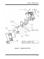
1
ESCORT® LC Pump Instruction Manual WARNING THIS MANUAL MUST BE CAREFULLY READ BY ALL INDIVIDUALS WHO HAVE OR WILL HAVE THE RESPONSIBILITY FOR USING OR SERVICING THE PRODUCT. Like any piece of complex equipment, the ESCORT LC Pump will perform as designed only if it is used and serviced in accordance with the manufacturer’s instructions. OTHERWISE, IT COULD FAIL TO PERFORM AS DESIGNED AND PERSONS WHO RELY ON THIS PRODUCT FOR THEIR SAFETY COULD SUSTAIN SEVERE PERSONAL INJURY OR DEATH. The warranties made by Zefon International Inc. with respect to the product are voided if the product is not used and serviced in accordance with the instructions in this manual. Please protect yourself and others by following them. We encourage our customers to write or call regarding this equipment prior to use or for any additional information relative to use or repairs. In the U.S., contact Zefon at 1-800-282-0073. To contact Zefon outside the U.S., dial +1 (352) 854-8080 or email at [email protected]. © Zefon International, Inc. 2011 - All Rights Reserved Manufactured by ZEFON INTERNATIONAL INCORPORATED 5350 SW 1ST LANE • OCALA, FL 34474 (L) Rev 3 814605 Warnings and Cautions WARNINGS 1. Do not charge the battery pack in areas that may contain a flammable mixture of combustible gases, vapors, or dust and air; otherwise, an explosion may occur because a source of ignition exists during charging. 2. Do not operate the pump in oxygen-enriched atmospheres (more than 21% oxygen) containing combustible gases, vapors, or other materials. Fire or explosion can result from operating in these atmospheres. Operate the pump with Zefon/MSA P/N 497702 or 10087242 BatteryPack only. Do not use other batteries or power sources. 3. 4. This pump is approved by UL for use in Class I, Groups A, B, C and D; Class II, Groups E, F, G; and Class III, specified in the National Electric Code (NEC). Do not use in hazardous areas (with respect to fire or explosion) other than those specified. Hazardous location classifications are further explained in the NEC Code. A copy can be obtained from the National Fire Protection Association, Batterymarch Park, Quincy, MA 02269. 5. Use only genuine Zefon replacement parts when performing maintenance procedures described in this manual; failure to do so may seriously impair pump performance. Repair or alteration beyond the scope of these maintenance instructions or by anyone other than authorized Zefon service personnel could cause the product to fail to perform as designed, and persons who rely on this product for their safety could sustain severe personal injury or death. FAILURE TO COMPLY WITH THE ABOVE WARNINGS CAN RESULT IN SERIOUS PERSONAL INJURY OR DEATH. W&C-1 Warnings and Cautions CAUTIONS 1. 2. 3. Do not use the pump with organic fluids in an impinger without an absorber trap; otherwise, the pump will be damaged. Use only a Zefon or MSA Omega™ () Charger to charge this pump. If, after thoroughly reading this manual, you are uncertain of the installation, operation, or maintenance procedures, call 1-800-282-0073 for assistance. W&C-2 Table of Contents Section 1 General Information ....................................... 1-1 Introduction..................................................................................1-1 Operating Specifications .........................................................1-1 Section 2 Theory of Operation ....................................... 2-1 Introduction..................................................................................2-1 Section 3 Operation ....................................................... 3-1 Charging the Battery Pack ...........................................................3-1 Operating Time.............................................................................3-1 Figure 3-1. Typical Operating Time Graph ...............................3-2 Personal/Area Sampling ..............................................................3-3 Figure 3-2. Front View with Cover Removed ...........................3-3 Operating the Pump .....................................................................3-4 Section 4 Routine Maintenance ..................................... 4-1 Periodic Maintenance ..................................................................4-1 Charging Spare or Idle Battery Packs .....................................4-1 Checking the Inlet Filter ..........................................................4-1 Filter Replacement ..................................................................4-1 Frit Replacement .....................................................................4-1 Battery Pack Replacement...........................................................4-2 Figure 4-1. Checking the Inlet Filter.......................................4-2 Figure 4-2. Replacing the Battery Pack .................................4-3 TOC - 1 Section 5 Maintenance .................................................. 5-1 Troubleshooting ...........................................................................5-1 Table 5-1. Troubleshooting Guidelines ...................................5-2 Pump & Drive Assembly Replacement .........................................5-4 Printed Circuit Control Board Replacement .................................5-4 Obtaining Replacement Parts ......................................................5-5 Table 5-2. Replacement Parts List .........................................5-5 Figure 5-1. Replacement Parts ..............................................5-7 TOC - 2 Section 1, General Information Section 1 General Information Introduction Congratulations on your purchase of the ESCORT LC Pump, an instrument designed for industrial hygiene filters, impinger, and charcoal tube sampling and backed by years of Zefon quality, dedication, and service. Operating Specifications Electrical Characteristics POWER SUPPLY 4.8-volt battery pack of four nickle-cadmium cells BATTERY PACK CAPACITY 1.8 ampere hour BATTERY PACK RECHARGING TIME 14-16 hours (overnight) with recommended chargers CHARGING TEMPERATURE 10 to 30º Centigrade (50 to 86º Fahrenheit) TYPICAL BATTERY PACK LIFE 300 or more charging cycles Operating and Physical Characteristics 5 to 25 inches of water load from 0.5 to 2.0 LPM, 5 to 20 inches of water load up to 2.5 LPM, and 5 to 10 inches of water load up to 3.0 LPM Varies with flow rate and sampling device loading. Minimum 10-hour operation at 2.5 LPM with OPERATING TIME 20-inch water load (see FIGURE 3-1). Pump automatically shuts off and lights the LOW BATT LOW BATTERY FUNCTION light when battery voltage drops below 4.1 volts. OPERATING TEMPERATURE 0 to 45º Centigrade (32 to 113º Fahrenheit) OPERATING RANGE 1-1 Section 1, General Information Operating Specifications DIMENSIONS WEIGHT CASE SERIAL NUMBER IDENTIFICATION 1-2 2 inches deep x 4 inches high x 3 7/8 inches wide (5.1 centimeters deep x 10.3 centimeters high x 9.8 centimeters wide) 18 oz. (510 grams) Case plastic is electrically conductive to reduce radio frequency interference; an optional leather case is available for pump protection during rough usage. Located on the side of the case under the battery pack (include number in correspondence to Zefon) Section 2, Theory of Operation Section 2 Theory of Operation Introduction The ESCORT LC Pump contains a diaphragm pump driven by an eccentric on a motor shaft. A rechargeable battery pack powers the motor. The flow rate is set by turning the flow control, which adjusts the motor speed. After this adjustment is made, internal circuitry controls the motor speed to minimize fluctuations in flow rate resulting from changes in sampling device loading and battery pack voltage. Each revolution of the motor produces one pump stroke, which causes the diaphragm to draw ambient air through the sampling device. Sample air flows through a replaceable filter that traps particulate matter at the pump inlet to prevent their entry into the pump. The pump has an integral pulsation dampener that minimizes pulsations in sample flow resulting from the pumping action. The sample air exhausts directly to the interior of the case and, from there, to the outside through holes in the case under the battery pack. 2-1 Section 3, Operation Section 3 Operation Charging the Battery Pack Use any of three Omega™ chargers (P/N 494716, 495965, or 801759) for charging the battery pack. Remove the charge jack plug and charge the battery pack for 14 to 16 hours. (Note that continuous charging for longer periods does not reduce battery life, provided the charging is performed at room temperature (50 to 86º F). The battery pack may also be charged when removed from the pump. Always replace the charge jack plug after charging and before using the pump. The plug prevents water entry into the jack. WARNING Do not charge the battery pack in areas that may contain a flammable mixture of combustible gases, vapors, or dust and air; otherwise, an explosion may occur because a source of ignition exists during charging. CAUTION Use only a ZEFON or MSA Omega™ () charger to charge this pump. Operating Time The maximum expected operating time for a pump with a fully charged battery pack depends on: 1. The selected flow rate. 2. The vacuum load imposed by the sampling device. 3. The temperature. 4. The age of the battery pack. 3-1 Section 3, Operation Figure 3-1. Typical Operating Time Graph See FIGURE 3-1 for approximate operating times. The shaded area shows operating loads and flow rates within the pump specifications. The example shown with dashed lines is for a pump set for 2.0 LPM with a sampling load of 15”; the expected maximum operating time would be 11.5 hours. This figure allows for the reduction of battery capacity which results from discharge cycles and low temperature operation. A new battery pack operated at room temperature will provide operating times of about two hours more than shown. Personal/Area Sampling The ESCORT LC Pump is designed for either personal or area sampling of ambient air. It automatically provides a constant volumetric flow rate of the sample air through external collection or sampling devices (filter discs, impingers, or charcoal tubes) to measure the concentration of airborne mists, dusts, particulates, gases, and vapors in the work-place. 3-2 Section 3, Operation CAUTION Always operate the ESCORT LC Pump with an external filter cassette or other sampling device. Continuous operation with an open inlet in a dirty atmosphere causes premature clogging of the inlet filter in the pump. Operating the Pump 1. Charge the battery pack (refer to “Charging the Battery Pack” in this section) or exchange a discharged pack with a charged spare. 2. Connect the desired sample device to the inlet fitting using flexible tubing. (The fitting accepts up to 5/16” ID tubing.) Figure 3-2. Front View with Cover Removed 3-3 Section 3, Operation 3. Open the switch cover. Then, press the ON/OFF switch. momentarily with a small screwdriver. The LED will light. 4. Adjust the flow rate control to the setting required for the sampling device being used. 5. At the end of the sampling period, open the switch cover and press the ON/OFF switch. 6. Charge the battery pack 14 to 16 hours by perfoming the procedure described under “Charging the Battery Pack”. NOTE 1: Calibrate the pump with a pump calibrator. For greatest accuracy, measure the pump flow rate using a primary flow standard with the sampling device or a substitute load equal to that of the sampling device attached to the pump inlet. Operate the pump several minutes at the selected flow rate with the sampling device attached to allow the temperature compensation circuitry to come to equilibrium before calibrating the flow rate. This equilibrium time is more important at higher flow rates (> 2 LPM) and higher loads (> 10 inches of water) due to motor warm-up. NOTE 2: OSHA (Volume VI-OSHA Technical Manual, March 26, 1990, OSHA 3058) recommends calibrating the pump flow both at the start of a sample period and at the end with either a primary or secondary calibration standard. This is most important in sampling situations where there is the possibility of extreme sampling device loading which may effect the sample flow rate. 3-4 Section 4, Routine Maintenance Section 4 Routine Maintenance Periodic Maintenance Charging Spare or Idle Battery Packs The nickel-cadmium cells in the battery pack lose their charge if not used for long periods. For this reason, do not store the pump without operating and charging it at least once a month. Checking the Inlet Filter The inlet fitting contains a dust filter (FIGURE 4-1) to protect the pump. If the filter becomes clogged, the sample flow may be blocked and he extra load placed on the motor will reduce the operating time. Therefore, check the filter regularly. The frequency of the checks should depend on the amount of pump usage and the concentration of particles allowed to enter the pump. An optional water filter is avaiable. It should be installed under the dust filter as shown in FIGURE 4-1. Filter Replacement 1. Remove the four screws holding the filter cover and O-ring. 2. Replace the filter with a new one. 3. Re-assemble the O-ring and cover. Frit Replacement (Replacement is rarely necessary if filter is properly maintained.) 1. Stab the frit center with a small screwdriver and lift it out. 4-1 Section 4, Routine Maintenance _______________________________________ *Teflon is a registered trademark of the Du Pont Company Figure 4-1. Checking the Inlet Filter 2. Press in a new frit. 3. Re-assemble the filter, O-ring, and cover. Battery Pack Replacement (FIGURE 4-2 illustrates the battery pack.) 4-2 Section 4, Routine Maintenance Figure 4-2. Replacing the Battery Pack 1. Remove the two screws securing the battery pack to the case. 2. Separate the pack from the case. Mark the battery pack to prevent its re-use. 3. Make sure that the O-ring is in place on the replacement pack. Then, slide the pack into the pump case while pressing the case front and back to make sure the case edges go inside the edges of the pack. 4. Press the battery pack into the pump case while replacing the two screws. NOTE: When the battery is replaced, the pump may turn ON and / or the LOW BATT LED may light. Press the ON/OFF switch to reset the pump to its normal OFF condition. 4-3 Section 5, Maintenance Section 5 Maintenance Troubleshooting TABLE 5-1, “Troubleshooting Guidelines,” lists the symptoms of the most commonly occurring problems; it also lists their probable cause(s) and the action required to correct each problem. Use the guidelines if you cannot calibrate the ESCORT LC Pump, or if the pump does not operate properly. WARNING Use only genuine ZEFON replacement parts when performing the maintenance procedures described in this manual. Failure to do so may seriously impair instrument performance. Repair or alteration beyond the scope of these maintenance instructions or by anyone other than a ZEFON-authorized service person could cause the product to fail to perform as designed, and persons who rely on this product for their safety could sustain severe personal injury or death. 5-1 Section 5, Maintenance Table 5-1. Troubleshooting Guidelines SYMPTOM Pump turns OFF prematurely and LOW BATT LED lighted PROBABLE CAUSE 1. Inlet filter clogged, causing high loading 2. Battery pack is degraded or not charged 1. Pump motor connector plugged into pc board improperly LED indicator turned ON and pump will not operate 2. Pump motor inoperative 3. PC board inoperative 5-2 CORRECTIVE ACTION 1. Replace filter according to “Checking the Inlet Filter” 2. Install new pack on pump by performing procedure described under “Battery Pack Replacement” or see “Charger” portion of this table 1. Check connector 2. Replace pump and motor drive assembly according to procedure under “Replacing the Pump and Drive Assembly” 3. Replace with new pc control board continued Section 5, Maintenance Table 5-1. Troubleshooting Guidelines (cont.) SYMPTOM -CHARGERLED Indicator on charger does not turn ON when connected to an electrical outlet and plug on charging cord is inserted in jack on battery pack Desired flow rate connot be obtained under heavy sampling device loads within regime of FIGURE 3-1 PROBABLE CAUSE CORRECTIVE ACTION 1. Power source inactive 1. Check and correct cause of power loss 2. Charger failure 2. Replace charger 3. Battery pack failure 3. Replace battery pack by performing procedure under “Replacing the Battery Pack” 1. Inlet filter partially clogged 2. Leak exists in sample flow system 1. Replace filter according to instructions under “Checking the Inlet Filter” 2. Check for leaking tube connection to the sampling device or the O-ring seal at the inlet filter cover 5-3 Section 5, Maintenance Pump & Drive Assembly Replacement 1. Remove two screws securing the battery pack to the case. 2. Remove the battery pack. 3. Remove the two screws securing the pump case. 4. Pull the motor electrical connector from the pc board. 5. Remove the two screws securing the pump mounting collar to the back of the case. 6. Lift out the pump and drive while removing the dampener conection from the fitting. Use soap solution (SNOOP*) to help slide the connection from the fitting. 7. Install the replacement pump and drive by reversing this procedure. NOTE: The short side of the motor collar must be face down. Tighten the upper motor collar screw before tightening the lower motor collar screw. Printed Circuit Control Board Replacement 1. Remove the two screws securing the battery pack. 2. Remove the battery pack. 3. Remove the two screws securing the pump case. 4. Pull the motor electrical connector from the pc board. 5. Remove and save the three screws, two washers and spacer securing the pc board to the pump face. 6. Install the replacement pc board by reversing this procedure. NOTE: Be sure the battery connector is mounted with the black wire towards the top of the case. _______________________________________ *SNOOP is a trademark of the Swagelok Company 5-4 Section 5, Maintenance Obtaining Replacement Parts The ESCORT LC Pump parts and part numbers are listed in TABLE 5-2. To obtain parts, service, or information in the U.S., call Zefon International at 1-800-282-0073. International customers can call +1 (352) 854-8080. Table 5-2. Replacement Parts List PART/COMPONENT PART NO. Kit, Pump Maintenance Parts • Belt Clips • Filter Cover • Screws (filter cover) • Charge Jack Caps • O-Rings (battery pack) 802922 • Screws (belt clip) • Screws (case) • Polyethylene Discs • O-Rings (filter cover) • Inlet Filters If pump is adapted for bag sampling (hole drilled in top left for an outlet) Fitting 655240 Tubing 602294 5-5 Section 5, Maintenance Table 5-2. Replacement Parts List (cont.) FIGURE 5-1 ITEM NO. PART NO. 1 Pump and Drive Assembly 2 Collar 800025 3 Printed Circuit-Board Assembly 814153 4 Screw 636493 5 O-Ring 636602 6 Screw 636414 7 Belt Clip 636293 8 Screw 636416 9 Screw 636415 10 Spacer 628852 11 Lock Washer 64095 12 Switch Cover Assembly (includes the screw) 802381 Screw 636418 FIGURE 4-1 FIGURE 4-2 not shown 5-6 PART/COMPONENT 813607 Filter Cover 497393 O-Ring 637009 Dust Filter (pkg of 5) 808935 Filter, Teflon (optional) 802897 Filter Frit 800303 Battery Pack (includes O-ring) 497702 Charge Jack Plug 802895 Instruction Manual 814605 Screwdriver 632655 Leather Case (optional) 811741 Battery Charger (120-volt) 494716 Battery Charger (230-volt) 495965 Battery Charger (5-unit) 801759 Section 5, Maintenance 5-7 Manufactured by ZEFON INTERNATIONAL INCORPORATED 5350 SW 1ST LANE • OCALA, FL 34474 • USA