1
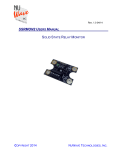
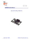
Rev.2.2 12/13
SSRMAN-1B SERIES USERS MANUAL
SSR INTELLIGENT BURST FIRING CONTROL
COPYRIGHT 2013
NUWAVE TECHNOLOGIES, INC.
SSRMAN-1B Users Manual
Page 2
TABLE OF CONTENTS
Ordering Codes ................................................................................................................................................. 2
Description ......................................................................................................................................................... 2
2.1
Features .................................................................................................................................................... 3
3.
Installation / Safety Information ......................................................................................................................... 3
3.1
Solid State Relay Installation .................................................................................................................... 3
3.2
Mounting Instructions ................................................................................................................................ 3
3.3
Electrical Connections .............................................................................................................................. 4
3.3.1
Internal Diagram ............................................................................................................................... 4
3.4
Limited Warranty....................................................................................................................................... 5
4.
Operation ........................................................................................................................................................... 5
4.1
Power Supply ............................................................................................................................................ 5
4.2
24V Power Fusing ..................................................................................................................................... 5
4.3
Command Input ........................................................................................................................................ 5
4.3.1
Input Fail-safe Protection ................................................................................................................. 5
4.4
Cycle Times .............................................................................................................................................. 5
4.5
Power Limit ............................................................................................................................................... 6
4.5.1
Power Limit Adjustment Procedure .................................................................................................. 6
4.6
Configuration Dipswitch ............................................................................................................................ 6
4.7
Control Output........................................................................................................................................... 7
4.8
Output LED ............................................................................................................................................... 7
4.9
Three Phase Operation............................................................................................................................. 7
4.9.1
Three Phase Operation – Cycle Times ............................................................................................ 8
4.10
Wiring Multiple Units ................................................................................................................................. 8
4.10.1
Connecting Power & Commands In Parallel .................................................................................... 8
5.
Electrical Specifications ..................................................................................................................................... 9
6.
Mechanical Dimensions ..................................................................................................................................... 9
7.
Contact Information ........................................................................................................................................... 9
8.
WIRING DIAGRAM (4-20mA, 0-5V, 0-10V Inputs) ......................................................................................... 10
9.
WIRING DIAGRAM (Potentiometer Input) ...................................................................................................... 10
10.
WIRING DIAGRAM (0-135 Ohm Input) ...................................................................................................... 11
11.
WIRING DIAGRAM 3 PHASE DELTA CONNECTION ............................................................................... 11
12.
WIRING DIAGRAM 3 PHASE WYE ........................................................................................................... 12
1.
2.
1. Ordering Codes
Part#
SSRMAN-1B
SSRMAN-1B-135
SSRMAN-1B-REV
SSRMAN-1B-PL
Description
SSR Mount Burst Firing Control
Module, Volts, mA Input, Pot
SSR Mount Burst Firing Control
Module, 0-135
Input, 24VAC
Power Only
Reverse Acting Output Option
Inputs
0-10V, 0-5V, 2-10V, 1-5V, 420mA, 0-20mA, Potentiometer
0-135
0-10V, 0-5V, 2-10V, 1-5V, 420mA, 0-20mA, Potentiometer
SSR Mount Burst Firing Control 0-10V, 0-5V, 2-10V, 1-5V, 4with power limit option
20mA, 0-20mA, Potentiometer
2. Description
The SSRMAN-1B is a burst firing control module designed for use with standard footprint
zero cross or random fire SSRs (Solid State Relays). The module mounts directly on the
SSR’s input screws. The module operates by varying duty cycle of SSR’s control input.
The power delivered to the load is proportional to the command input signal.
Copyright 2013
NUWAVE TECHNOLOGIES, INC.
SSRMAN-1B Users Manual
Page 3
2.1 Features
Command input accepts 4-20mA, 0-10V, 0-5V, 0-135 , Potentiometer
Configurable for 4 different cycle times
Drives multiple solid state relays (SSRs)
Small (1.75x1.40”) module mounts on the input terminals of an inexpensive SSR
Fits under finger-safe covers
LED output indicator
Adjustable Power Limit (-PL) Option
Single phase and three phase control
3. Installation / Safety Information
Responsibility for determining suitability for use in any application / equipment lies solely on
the purchaser, OEM and end user. Suitability for use in your application is determined by
applicable standards such as UL, cUL and CE and the completed system involving this
component should be tested to those standards.
WARNING: FIRE HAZARD!! Even quality electronic components
CAN FAIL KEEPING FULL POWER ON! Provide a SEPARATE (redundant) OVER
TEMPERATURE SHUTDOWN DEVICE to switch the power off if safe temperatures are
exceeded.
WARNING: HIGH VOLTAGE!! This control is installed on a Solid State
Relay with high voltage on it. This control must be installed in a GROUNDED enclosure by
a qualified electrician in accordance with applicable local and national codes including NEC
and other applicable codes. Provide a safety interlock on the door to remove power before
gaining access to the device.
3.1 Solid State Relay Installation
Make sure that the voltage and current ratings of the Solid State Relay
(SSR) are sized correctly for the load, otherwise a hazardous condition such as
over-heating, failure of the SSR, fire or explosion may result. Contact the SSR
manufacturer for more details.
The SSR must be mounted to a heat sink as per the SSR
manufacturers requirements, otherwise a hazardous condition such as overheating, failure of the SSR, fire or explosion may result. Contact the SSR
manufacturer for more details.
3.2 Mounting Instructions
Copyright 2013
NUWAVE TECHNOLOGIES, INC.
SSRMAN-1B Users Manual
Page 4
The SSRMAN mounts directly to the control input terminals of an
SSR using two #6-32 screws. Some relays have short input
screws and longer screws will required to reach through the
contacts on the SSRMAN.
Be sure to observe the correct polarity when mounting the module
(module should be positioned over the SSR). The module should
sit firmly on top of the SSR when the screws are tightened.
3.3 Electrical Connections
See the WIRING DIAGRAMS at the end of this
document. Make sure the module ordered is
the correct module for the application before
wiring.
Before wiring the module all Dip Switch
settings for the command input and special
features should be setup properly per the
Dipswitch Configuration Section.
The terminal blocks on the sides of the
SSRMAN for connecting 24V Power and the
command signal can accept 16-30 AWG wire.
3.3.1 Internal Diagram
Please reference the internal diagram below to be absolutely sure that the system wiring
will be compatible with the control module.
Copyright 2013
NUWAVE TECHNOLOGIES, INC.
SSRMAN-1B Users Manual
Page 5
3.4 Limited Warranty
NuWave Technologies, Inc. warrant this product to be free from defect in workmanship
and materials for a period of two (2) years from the date of purchase.
1. Should unit malfunction, return it to the factory. If defective it will be repaired or
replaced at no charge.
2. There are no user serviceable parts on this unit. This warranty is void if the unit shows
evidence of being tampered with or subjected to excessive heat, moisture, corrosion or
other misuse / misapplication.
3. Components which wear or damage with misuse are excluded, e.g. relays.
4. NuWave Technologies, Inc. shall not be responsible for any damage or losses however
caused, which may be experienced as a result of the installation or use of this product.
NuWave Technologies, Inc. liability for any breach of this agreement shall not exceed
the purchase price paid E. & O.E.
4. Operation
4.1 Power Supply
The SSRMAN-1B power requirement is 24V AC +/-15% 47-63Hz, 24VDC +30/-10%.
4.2 24V Power Fusing
Fusing may be accomplished by fusing each module separately or fusing groups of the
modules with either primary or secondary fusing. The current draw of each SSRMAN-1B
is 65mA max.
4.3 Command Input
The SSRMAN-1B can accept 4-20mA, 0-10V, 0-5V, and Potentiometer. The SSRMAN1B-135 can only accept a 0-135
Input, and must be used with 24VAC Power. All
command inputs are not isolated from the 24V power input; they share a common
ground. The type of command input can be configured via the dipswitch. The default
setting is 0-5V/potentiometer.
When wiring multiple SSRMAN-1B’s together, follow the guidelines in the Wiring Multiple
SSRMAN-1Bs section.
Any leg of the command input can tolerate shorts to the (0V) input. Connecting the 24V
power to the command input will cause damage to the unit.
When 4-20mA is selected via the dipswitch, a 249 Ohm shunt resistor is present at the
command input between the 0V and IN terminals. Be sure not to exceed 20mA DC on
the input as damage to the unit may result. If the command input is wired to a 0-20mA or
4-20mA output of another device, the 0V terminal must remain at the same potential as
the negative lead of the current output from the other device, otherwise damage to the
SSRMAN may result.
4.3.1 Input Fail-safe Protection
If the signal sent to the SSRMAN-1B’s command input should become electrically open the
control output will be forced to an off or less than 5% output power state.
4.4 Cycle Times
The SSRMAN-1B has 4 available cycle times of 200mS, 1S, 10S, and 100S.
Copyright 2013
NUWAVE TECHNOLOGIES, INC.
SSRMAN-1B Users Manual
Page 6
Generally the cycle time should be chosen based on the mass of the load to be
controlled; the larger the load mass, the longer the cycle time can be. Generally, it is
best to choose the longest cycle time that can be used without causing process ripple.
4.5 Power Limit
The Power Limit option can be ordered as SSRMAN-1B-PL. The Power Limit feature is
used to limit the average power delivered to the load. The power limit is adjustable via a
potentiometer located just below the input terminal block. The Power limit feature is only
available for use with 24VAC Power.
4.5.1 Power Limit Adjustment Procedure
The Power Limit is adjustable from 10% to 100% of the max load power (0-100% for 15Vor 4-20mA ranges). Setting the Power Limit potentiometer half way corresponds to a
power limit of approximately 55%. With the command input set to approximately 100%
(on startup) turn the pot fully CCW. Then just turn the pot CW until the desired output
power is achieved.
4.6 Configuration Dipswitch
0-135R
4-20mA
0-10V
CYT A
4-20mA
CYT B
The configuration dipswitch is used for setting up the command input, and the cycle time.
Using a pen point gently push the switch up for on and down for off according to the
setup outlined in the table below.
Command Input
0-5V (Default)
Potentiometer
0-10V
4-20mA
1-5V
Copyright 2013
1
OFF
OFF
OFF
OFF
OFF
2
OFF
OFF
OFF
ON
OFF
3
OFF
OFF
ON
OFF
OFF
5
OFF
OFF
OFF
ON
ON
NUWAVE TECHNOLOGIES, INC.
SSRMAN-1B Users Manual
Page 7
OFF
OFF
2-10V
ON
OFF
OFF
ON
0-135 *
*Module must be ordered as SSRMAN-1B-135 for 0-135 input support.
135 input support is only useable with 24VAC Power.
Cycle Time
200mS
1 Second
10 Seconds
100 Seconds
4
OFF
OFF
ON
ON
ON
OFF
6
OFF
ON
OFF
ON
4.7 Control Output
The SSRMAN-1B SSR output drive is a DC pulsed current limited drive signal of
10V/15mA (24VAC power) or 10V/9.5mA (24VDC power). This is more than enough
current for driving most 3-32V standard SSRs, however it is still important to review the
data sheet for the SSR you would like to use for compatibility with the SSRMAN-1B’s
output drive. The control output can tolerate a momentary direct short. The following
graph will allow you to verify the SSR’s compatibility with the SSRMAN-1B over wide
input voltage variations.
SSR DRIVE CURRENT (mADC)
30
25
+1
20
24
VA
C
-10
15
24V
DC
10
5
0
%
0%
(NO
MIN
AL)
(NO
MIN
AL) +
10
-10 %
%
10
5
15
SSR INPUT VOLTAGE DROP (VDC)
20
SSRMAN-1B Output Drive Current vs. SSR Input Voltage Drop
4.8 Output LED
The SSRMAN-1B’s RED output LED will turn on when the output is on. The output LED
is wired in series with the SSR’s input. If there is a poor connection on the SSR input
terminals or a problem with the SSR’s Input, the output LED will not become energized.
4.9 Three Phase Operation
One SSRMAN-1B can be used to control two poles of a three phase load using two
SSRs with their control inputs wired in parallel. The Module should be wired as shown in
the three phase wiring diagrams sections. The Control Output section should be reviewed
to make sure that the total input current requirements of the two SSRs can be achieved
with the SSRMAN-1B.
Copyright 2013
NUWAVE TECHNOLOGIES, INC.
SSRMAN-1B Users Manual
Page 8
4.9.1 Three Phase Operation – Cycle Times
When using the SSRMAN-1B to control three phase loads, the cycle time should be set
for at least one second and preferably 10 or 100 seconds. This will maximize the control
resolution and minimize any load imbalances.
4.10 Wiring Multiple Units
If more than one SSRMAN-1B is to be used from a non-isolated or common command
signals:
1. A common power transformer can be shared. If the input selected is 0-10V or 05V, the inputs should be wired in parallel.
2. If multiple units must be powered from one power transformer and 4-20mA input is
selected, one module should be set for 4-20mA and the remaining modules should
be set for 1-5V.
3. If the command is 4-20mA, and the command inputs are to be wired in series, a
separate power transformer for each module is required to isolate the inputs.
4.10.1 Connecting Power & Commands In Parallel
When multiple SSRMAN-1B power inputs and commands are wired in parallel, all of the
0V terminals must be connected together follows:
Power:
Command:
0V-----0V-----0V----->
0V-----0V-----0V----->
24V---24V---24V---->
IN------IN-----IN------>
No crossing of the power input feed or command signal is permitted. If for some reason
the power should become crossed, it will cause a direct short in the system. If properly
fused, the fuse will blow and the SSRMAN-1B will not be damaged. If the command
inputs are wired improperly, damage to SSRMAN-1B can result.
We do not guarantee operation of the SSRMAN-1B with any other manufacturer's SSR
control module. Using them in the same circuit may cause either module to be
damaged.
Copyright 2013
NUWAVE TECHNOLOGIES, INC.
SSRMAN-1B Users Manual
Page 9
5. Electrical Specifications
Command Inputs
Input Impedance
0-135 Excitation Current
Control Output
10V at 9.5mA (24VDC)
Output Resolution
Output Linearity
Power Limit Range
External Potentiometer Res.
Ambient Temperature Range
Power Supply
Power Consumption
Line Frequency Range
Terminal Block wire Gauge
Terminal Block Material
4-20mA, 0-10V, 0-5V, 0-135 , Pot, 0-135
10K (0-10V), 250 (4-20mA), 100K (0-5V)
13mA max
SSR Drive, nominally 10V at 15mA (24VAC)
0.5% for 4-20mA, 0-5V, pot and 0-10V. 1% for 0-135
1.5% for 4-20mA, 0-5V, pot and 0-10V. 5% for 0-135
10-100% of max load power.
10K -25K
0 to 60 °C
24VAC +15/-15%, 24VDC +30%/-10%
65mA (Power consumption 1.6W MAX)
(24VAC power) 47-63 Hz
16-30 AWG
Polyamide 6.6 UL 94 V-0, Black
6. Mechanical Dimensions
0-135R
4-20mA
0-10V
CYT A
4-20mA
CYT B
1.40"
1.75"
Max Height is 0.6”
7. Contact Information
NuWave Technologies, Inc
866-379-3597
www.nuwaveproducts.com
Copyright 2013
NUWAVE TECHNOLOGIES, INC.
SSRMAN-1B Users Manual
Page 10
8. WIRING DIAGRAM (4-20mA, 0-5V, 0-10V Inputs)
SSRMAN-1B WIRING DIAGRAM (4-20mA, 0-5V, 0-10V INPUT)
AC POWER
SOURCE
N
HEATER
L
FUSE
SSR
0-135R
4-20mA
0-10V
CYT A
4-20mA
CYT B
PROCESS
+
CONTROLLER
4-20mA,
0-5V,OR
0-10V
FUSE
24VAC/DC
CONTROL
TRANSFORMER
9. WIRING DIAGRAM (Potentiometer Input)
SSRMAN-1B WIRING DIAGRAM (POTENTIOMETER INPUT)
AC POWER
SOURCE
N
HEATER
L
FUSE
CCW
SSR
CW
0-135R
4-20mA
0-10V
CYT A
4-20mA
CYT B
W
POTENTIOMETER
FUSE
24VAC/DC
CONTROL
TRANSFORMER
Copyright 2013
NUWAVE TECHNOLOGIES, INC.
SSRMAN-1B Users Manual
Page 11
10. WIRING DIAGRAM (0-135 Ohm Input)
SSRMAN-1B WIRING DIAGRAM (0-135 Ohm Input)
N
AC POWER
SOURCE
HEATER
L
FUSE
0-135R
4-20mA
0-10V
CYT A
4-20mA
CYT B
SSR
0-135 Ohm
Thermostat
FUSE
24VAC/DC
CONTROL
TRANSFORMER
11. WIRING DIAGRAM 3 PHASE DELTA CONNECTION
3 PHASE DELTA CONNECTION
SSRMAN-1B LOAD WIRING DIAGRAM
FUSE
SSR
HEATER2
0-135R
4-20mA
0-10V
CYT A
4-20mA
CYT B
L1
COMMAND INPUTS:
WIRED IN PARALLEL FOR 0-10V
WIRED IN SERIES FOR 4-20MA
L2
HEATER1
HEATER3
FUSE
L3
FUSE
SSR
Copyright 2013
NUWAVE TECHNOLOGIES, INC.
SSRMAN-1B Users Manual
Page 12
12. WIRING DIAGRAM 3 PHASE WYE
3 PHASE WYE CONNECTION
SSRMAN-1B LOAD WIRING DIAGRAM
FUSE
SSR
HEATER2
0-135R
4-20mA
0-10V
CYT A
4-20mA
CYT B
L1
COMMAND INPUTS:
WIRED IN PARALLEL FOR 0-10V
WIRED IN SERIES FOR 4-20MA
L2
FUSE
HEATER3
HEATER2
L3
FUSE
SSR
Copyright 2013
NUWAVE TECHNOLOGIES, INC.