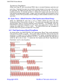
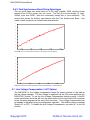
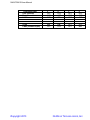
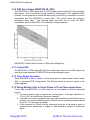
1
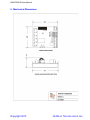
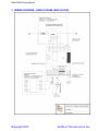
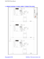
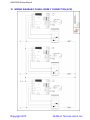
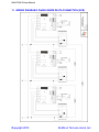
Rev.2.2 12/13
NWUPCM-1B SERIES USER MANUAL
SCR POWER CONTROL DRIVER BOARD
ZERO CROSS (BURST) FIRED
COPYRIGHT 2013
NUWAVE TECHNOLOGIES, INC.
NWUPCM-1B User Manual
TABLE OF CONTENTS
Ordering Codes ................................................................................................................................................. 2
Description ......................................................................................................................................................... 3
Installation / Safety Information ......................................................................................................................... 3
3.1
Mounting Instructions ................................................................................................................................ 4
3.2
Electrical Connections .............................................................................................................................. 4
3.3
SCR Output Snubbers and Transient Protection ..................................................................................... 4
3.3.1
dv/dt Problems ................................................................................................................................. 4
3.3.2
Snubber Design ............................................................................................................................... 4
3.3.3
Snubber Sizing ................................................................................................................................. 4
3.3.4
MOVs and TVSs .............................................................................................................................. 4
3.4
Limited Warranty ....................................................................................................................................... 4
4.
Operation ........................................................................................................................................................... 5
4.1
Power Supply ............................................................................................................................................ 5
4.2
24V Power Fusing .................................................................................................................................... 5
4.3
Command Input ........................................................................................................................................ 5
4.4
PWM Command Input .............................................................................................................................. 5
4.4.1
PWM Input ....................................................................................................................................... 5
4.4.2
Input Fail-safe Protection ................................................................................................................. 5
4.5
Cycle Times .............................................................................................................................................. 5
4.6
Cycle Times – 266mS Selection (Fast Synchronous Burst Firing) ........................................................... 7
4.6.1
Fast Synchronous Burst Firing Mode............................................................................................... 7
4.6.2
Fast Synchronous Burst Firing Advantages .................................................................................... 8
4.7
Line Voltage Compensation (-LVC Option) .............................................................................................. 8
4.7.1
Line Voltage Compensation Nominal Adjustment ........................................................................... 9
4.8
Power Limit ............................................................................................................................................... 9
4.8.1
Power Limit Adjustment Procedure .................................................................................................. 9
4.9
Configuration Dipswitch ............................................................................................................................ 9
4.10
SSR Drive Output (NWUPCM-1B- SSR) ................................................................................................ 11
4.11
Output LED ............................................................................................................................................. 11
4.12
Three Phase Operation .......................................................................................................................... 11
4.13
Wiring Multiple Units in Single Phase or Three Phase Applications ...................................................... 11
4.13.1
Connecting Power & Commands In Parallel .................................................................................. 12
5.
Electrical Specifications ................................................................................................................................... 12
6.
Mechanical Dimensions .................................................................................................................................. 13
7.
WIRING DIAGRAM - SINGLE PHASE (SSR OR SCR) .................................................................................. 14
8.
WIRING DIAGRAM 3 INSIDE DELTA CONNECTION (SSR) ........................................................................ 15
9.
WIRING DIAGRAM 3 PHASE 4 WIRE Y CONNECTION (SSR) .................................................................... 16
10.
WIRING DIAGRAM 3 PHASE 4 WIRE Y CONNECTION (SCR) ............................................................... 17
11.
WIRING DIAGRAM 3 PHASE INSIDE DELTA CONNECTION (SCR)....................................................... 18
12.
Contact Information ..................................................................................................................................... 19
1.
2.
3.
1. Ordering Codes
Ordering Codes
NWUPCM-1B-___
Power Control Module
Single Pole
Burst Fire
SCR or SSR
Part#
NWUPCM-1P-SSR
NWUPCM-1P-SCR
NWUPCM-1B-SSR
NWUPCM-1B-SCR
NWUPCM-1B-SSR-LVC
NWUPCM-1B-SCR-LVC
Copyright 2013
Description
Phase Angle Control Module SSR DRIVE (see NWUPCM-1P User Manual)
Phase Angle Control Module SCR GATE DRIVE (see NWUPCM-1P User Manual)
Burst Firing Control Module SSR DRIVE
Burst Firing Control Module SCR GATE DRIVE
Burst Firing Control Module SSR DRIVE
Burst Firing Control Module SCR GATE DRIVE
NUWAVE TECHNOLOGIES, INC.
NWUPCM-1B User Manual
2. Description
The NWUPCM-1 is a phase angle / burst fire control module designed for use with Solid
State Relays or high power back to back SCR modules. The power delivered to the load
is proportional to the command input signal.
Features:
Zero Cross Firing for low EMI
Fast Sychronous Burst Algorithm provides true linear power at fast cycle times
Small 3.0”x2.5”module mounts in a snap track or a dinrail
Command input accepts 4-20mA, 0-10V, 0-5V, Pot, PWM
Wide frequency operation (30 to 90Hz)
Adjustable Power % Limit
Drives multiple solid state relays
Drives SCR gates directly
Single phase and three phase control
3. Installation / Safety Information
Responsibility for determining suitability for use in any application / equipment lies solely on
the purchaser, OEM and end user. Suitability for use in your application is determined by
applicable standards such as UL, cUL and CE and the completed system involving this
component should be tested to those standards.
WARNING: FIRE HAZARD!! Even quality electronic components
CAN FAIL KEEPING FULL POWER ON! Provide a SEPARATE (redundant) OVER
TEMPERATURE SHUTDOWN DEVICE to switch the power off if safe temperatures are
exceeded.
WARNING: HIGH VOLTAGE!! This control module has high voltage on it.
This control must be installed in a GROUNDED enclosure by a qualified electrician in
accordance with applicable local and national codes including NEC and other applicable
codes. Provide a safety interlock on the door to remove power before gaining access to
the device.
The NWUPCM-1 contains fragile components that if damaged can cause
improper operation, failure or fire. While all units are inspected and tested at the factory,
damage can occur during shipping or installation. Before applying power, inspect each
module for damage paying specific attention to the pulse transformer drive coil. If there are
any abrasions or scratches on the coil wires, DO NOT APPLY POWER. The unit should be
sent back to the factory for repair.
Copyright 2013
NUWAVE TECHNOLOGIES, INC.
NWUPCM-1B User Manual
3.1 Mounting Instructions
The NWUPCM-1 mounts in a 3.0” snap track and can be installed on a dinrail.
3.2 Electrical Connections
See the WIRING DIAGRAMS at the end of this document. Make sure the module ordered
is the correct module for the application before wiring. Before wiring the module all Dip
Switch settings for the command input and special features should be setup properly per
the Dipswitch Configuration Section.
3.3 SCR Output Snubbers and Transient Protection
3.3.1 dv/dt Problems
When voltage transients occur on the mains supply or load of an SCR/TRIAC it can cause
the device to turn on unexpectedly due to the fast rate of rise of voltage (dv/dt). This can
result in false firing and half cycling of the load. An R-C snubber circuit will help to limit the
dv/dt seen by the device and will produce more reliable firing.
3.3.2 Snubber Design
Although most designers use an empirical approach to solving the aforementioned issues
with snubbers, a number of great articles have been published on the mathematical basis
for calculating snubber circuit values.
3.3.3 Snubber Sizing
When an SCR/TRIAC using an R-C snubber turns on, the capacitor is discharged through
the resistor into the device resulting in high peak currents. It is critically important when
sizing your snubber to make sure that the resistor value does not become so low that the
ratings of the SCR/TRIAC are exceeded when the capacitor is discharged.
3.3.4 MOVs and TVSs
Metal Oxide Varistors and Transient Voltage Suppressors are both used on TRIACS/SCRs
to “clamp” voltage spikes that can occur across the devices and damage them. Snubbers
are not a substitute for MOVs/TVSs and vice versa. Snubbers and MOVs/TVs should be
used together to get reliable performance and long life from the SCR/TRIAC application.
External MOVs must be installed across the SCRs to limit peak voltages accepted by the
NWUPCM to ~ 850VDC.
3.4 Limited Warranty
NuWave Technologies, Inc. warrant this product to be free from defect in workmanship
and materials for a period of two (2) years from the date of purchase.
1. Should unit malfunction, return it to the factory. If defective it will be repaired or
replaced at no charge.
2. There are no user serviceable parts on this unit. This warranty is void if the unit shows
evidence of being tampered with or subjected to excessive heat, moisture, corrosion or
other misuse / misapplication.
3. Components which wear or damage with misuse are excluded, e.g. relays.
Copyright 2013
NUWAVE TECHNOLOGIES, INC.
NWUPCM-1B User Manual
4. NuWave Technologies, Inc. shall not be responsible for any damage or losses however
caused, which may be experienced as a result of the installation or use of this product.
NuWave Technologies, Inc. liability for any breach of this agreement shall not exceed
the purchase price paid E. & O.E.
4. Operation
4.1 Power Supply
The NWUPCM-1 power supply requirement is 24V AC +/-10% 47-63Hz OR 24VDC+15/5%. The line synchronization for phase angle and certain modes of burst firing has an
input voltage range of 100 to 600VAC, 30 to 90Hz.
4.2 24V Power Fusing
Fusing may be accomplished by fusing each module separately or fusing groups of the
modules with either primary or secondary fusing. The current draw of each NWUPCM-1
is 100mA max.
4.3 Command Input
The NWUPCM-1 can accept 4-20mA, 0-10V, 0-5V, and Potentiometer and PWM inputs.
All analog command inputs are not isolated from the 24V power Input. The type of
command input can be configured via the dipswitch. The default setting is 05V/potentiometer.
The PWM digital command input (PLC Interface) is optically isolated from the power
supply.
When wiring multiple NWUPCM-1’s together, follow the guidelines in the Wiring Multiple
NWUPCM-1s section.
Any leg of the command input can tolerate shorts to the (0V) input. Connecting the 24V
power to the command input may cause damage to the unit.
4.4 PWM Command Input
The NWUPCM-1 PWM Command input is designed to accept a signal from a PLC or a
process/temperature controller’s SSR drive output. This logic signal is used to generate a
command setpoint.
4.4.1 PWM Input
The NWUPCM-1 accepts PWM signals from 500Hz-15KHz and logic voltages of 5VDC
(non isolated command input) or 24VDC (optically isolated PWM input). When using the
optically isolated PWM input, the PWM Dip Switch #6 must be set to “ON”. The PWM
input provides a low cost way to interface with a PLC or PC DAQ.
4.4.2 Input Fail-safe Protection
If the signal sent to the NWUPCM-1’s command input should become electrically open the
control output will be forced to an off state.
4.5 Cycle Times
The cycle time refers to the total time between an on and off cycle.
Copyright 2013
NUWAVE TECHNOLOGIES, INC.
NWUPCM-1B User Manual
The NWUPCM-1B has 4 available cycle times settable via the dipswitches.
The cycle times are specified below in # of cycles and can be correlated to their
respective times using the table below for both 50 and 60 Hz Line frequencies:
Dip
Switch 1
Dip
Switch 3
#of
cycles
*OFF
ON
OFF
ON
*OFF
OFF
ON
ON
~16
60
600
6000
Copyright 2013
Cycle
Time
(60Hz)
266mS
1S
10S
100S
Cycle
Time
(50Hz)
320mS
1.2S
12S
120S
Resolution
( % of FS)
~1%
1.66%
0.166%
0.0166%
NUWAVE TECHNOLOGIES, INC.
NWUPCM-1B User Manual
*Synchronous Firing Method
When burst firing AC with conventional PWM, there is a tradeoff between resolution and
cycle time. Generally the cycle time should be chosen based on the mass of the load to
be controlled; the larger the load mass, the longer the cycle time can be. For the best
possible resolution, its standard practice to choose the longest cycle time that can be
used without causing process ripple. Longer cycle times generally provide greater control
resolution, but the Fast Synchronous Burst setting provides excellent resolution at a fast
cycle time.
4.6 Cycle Times – 266mS Selection (Fast Synchronous Burst Firing)
When the NWUPCM-1B cycle time is set to 266mS (320mS @ 50Hz) the Fast
Synchronous Burst Firing mode is turned on. The cycle time becomes longer near zero
and full power levels to provide improved control resolution. For Example, since the
NWUPCM-1B generally modulates 16 AC cycles, the lower limit in power that will
maintain the cycle time is 1/16 or 6.25%. The NWUPCM-1B will use increased off
periods below 6.25% power and above 94.75% power.
4.6.1 Fast Synchronous Burst Firing Mode
As shown below, the NWUPCM-1B’s Fast Synchronous Burst Firing mode selectively
fires fractional numbers of cycles. Since pulse width modulation alone would limit the
resolution to 16 steps or 6.25% when modulating 16 AC cycles, a proprietary algorithm is
employed to provide improved resolution of 0.5-1%. In this firing mode, the cycle time is
varied as well as the on time. To select the Fast Synchronous Burst Firing Mode set
Diswitches 1 and 3 to the off position.
Copyright 2013
NUWAVE TECHNOLOGIES, INC.
NWUPCM-1B User Manual
4.6.2 Fast Synchronous Burst Firing Advantages
The two plots below are actual data for a 425 degF capable 10KW resistive heater
ramped from 0-100% power over two hours. The first plot shows straight 16 cycle,
266mS cycle time PWM. Note the nonlinearity humps due to poor resolution. The
second plot shows the linearity improvement with the Fast Synchronous Burst. Any
visible overall curvature is a normal heater characteristic.
450
400
350
300
250
200
150
100
50
17 3
:00
:0
17 5
:50
:0
18 2
:00
:0
18 4
:50
:0
19 1
:00
:0
hm
: n
i :s
Fast PWM of zero cross fired loads can result in poor linearity / resolution (above)
450
400
350
300
250
200
150
100
50
15 0
:00
:0
15 2
:50
:0
15 5
:00
:0
16 1
:50
:0
16 4
:00
:0
hm
: n
i :s
NuWave Fast Synchronous Burst algorithm results in excellent linearity / resolution (above)
4.7 Line Voltage Compensation (-LVC Option)
The NWUPCM-1‘s line voltage compensation keeps the power constant on the load as
the line voltage changes. The line voltage is measured via the 24V power applied to the
NWUPCM-1 module. To use the Line Voltage Compensation feature properly, a 24VAC
power transformer should be fed from the same mains as the load circuit to be controlled
as per the wiring diagrams at the end of this document. Line Voltage Compensation can
be enabled or disabled using the configuration dipswitch. The default setting is enabled
(Switch # 1 is OFF). To disable the Line Voltage Compensation, set switch # 1 to the ON
position.
Copyright 2013
NUWAVE TECHNOLOGIES, INC.
NWUPCM-1B User Manual
On the NWUPCM-1B, Line Voltage compensation can be ordered by adding –LVC to the
suffix of the part #. When line voltage compensation is specified, only the fast
synchronous burst cycle time is available (the dipswitch setting of cycle times is disabled).
With a 10% drop in line voltage, N WUPCM-1 load power drops less than 2%
(120V, 1KW, 14.4 O hm Load )
Withou t Line Voltage Compensation
N WUPCM-1 Line Voltage Compensation
120VAC
120VAC
108VAC
(-10%)
108VAC
(-10%)
MAINS VOLTAGE
1KW
MAINS VOLTAGE
1KW
P= E
R
LOAD POWER
LOAD POWER
0.81KW
(~-20%)
4.7.1 Line Voltage Compensation Nominal Adjustment
The nominal adjustment pot sets the nominal level of output for the current line voltage
being measured via the 24VAC input.
4.8 Power Limit
The Power Limit feature is used in conjunction with the Line Voltage Compensation
feature to limit the actual voltage delivered to the load. The Power Limit is adjustable via
a potentiometer located just below the input terminal block. For this feature to work
properly Line Voltage Compensation must be turned on and the power transformer for the
NWUPCM-1 must be connected to the same mains as the load power is connected to.
This feature can be used without Line Voltage Compensation and will simply clip the
command signal to a set level.
4.8.1 Power Limit Adjustment Procedure
The Power Limit is adjustable from 10% to 100% of the max power. Setting the Power
Limit potentiometer half way corresponds to a Power limit of approximately 55%. With the
command input set to approximately 100% (on startup) turn the pot fully CCW. Then just
turn the pot CW until the desired maximum output Power is achieved. For this feature to
work as a true max limit, it is important that the Line Voltage Compensation be enabled
(this is the OFF position of Switch # 1).
If the line voltage compensation is set to OFF or not present in the ordering code, the max
limit will act as a percentage of output limit and the absolute max limit will change with line
voltage.
4.9 Configuration Dipswitch
The configuration dipswitch is used for setting up the command input and Cycle Times.
Using a pen point gently push the switch up for on and down for off according to the setup
outlined in the table below.
Copyright 2013
NUWAVE TECHNOLOGIES, INC.
NWUPCM-1B User Manual
Command Input
0-5V (Default)
Potentiometer
0-10V
4-20mA
1-5V
2-10V
PWM (isolated input)
Copyright 2013
2
OFF
OFF
OFF
ON
ON
ON
OFF
4
OFF
OFF
ON
OFF
OFF
ON
OFF
5
OFF
OFF
OFF
ON
OFF
OFF
OFF
6
OFF
OFF
OFF
OFF
OFF
OFF
ON
NUWAVE TECHNOLOGIES, INC.
NWUPCM-1B User Manual
4.10 SSR Drive Output (NWUPCM-1B- SSR)
The NWUPCM-1’s SSR output drive is a DC-pulsed current limited 10V/15mA (nominal)
drive signal. This is more than enough current for driving most 3-32V standard SSRs,
however it is still important to review the data sheet for the SSR you would like to use for
compatibility with the NWUPCM-1’s output drive. The control output can tolerate a
momentary direct short. The following graph will allow you to verify the SSR’s
compatibility with the NWUPCM-1 over wide input voltage variations.
NWUPCM-1’s Output Drive Current vs. SSR Input Voltage Drop
4.11 Output LED
The NWUPCM-1’s RED output LED will turn on when the output is on the LED should can
used as a rough indication of SSR/SCR Drive and actual power output.
4.12 Three Phase Operation
Three NWUPCM-1s can be used to control three poles of a three phase load for inside
delta, or grounded WYE configurations. The Module should be wired as shown in the
wiring diagrams.
4.13 Wiring Multiple Units in Single Phase or Three Phase Applications
If more than one NWUPCM-1 is to be used from a non-isolated or common command
signals:
1. A common power supply or transformer can be shared. If the input selected is 010V or 0-5V, the inputs should be wired in parallel.
2. If multiple units must be powered from one power transformer and 4-20mA input is
selected, one module should be set for 4-20mA and the remaining modules should
be set for 1-5V and wired in parallel.
3. If the command is 4-20mA, and the command inputs are to be wired in series, a
separate power transformer or supply for each module is required to isolate the
inputs.
Copyright 2013
NUWAVE TECHNOLOGIES, INC.
NWUPCM-1B User Manual
4.13.1 Connecting Power & Commands In Parallel
When multiple NWUPCM-1 power inputs and commands are wired in parallel, all of the
0V terminals must be connected together follows:
Power:
Command:
0V-----0V-----0V----->
0V-----0V-----0V----->
24V---24V---24V---->
IN------IN-----IN------>
No crossing of the power input feed or command signal is permitted. If for some reason
the power should become crossed, it will cause a direct short in the system. If properly
fused, the fuse will blow and the NWUPCM-1 will not be damaged. If the command
inputs are wired improperly, damage to the NWUPCM-1 can result.
5. Electrical Specifications
Command Inputs
Input Impedance
SSR Control Output
Response Time
PWM Input Frequency
PWM Input Level
Output Linearity
External Potentiometer Res.
Line Voltage Comp. Range
Power Limit Range
Ambient Temperature Range
Power Supply
Line Frequency Range
Line Voltage Range
SCR Firing
SCR Gate Drive Characteristics
Copyright 2013
4-20mA, 0-10V, 0-5V, Pot, PWM
10K (0-10V), 250 (4-20mA), 100K (0-5V)
SSR Drive, DC pulse, nominally 10V at 20mA
<50mS
500Hz-15KHz
5 VDC (non isolated) or 24VDC (isolated)
+/-2%
10K -25K
+15%/-15% up to 100% output
10-100% of max load power
0 to 50 °C
24VAC/DC +10/-10%, <100mA Current Draw.
30 to 90Hz
100-600VAC (External MOV must be installed across
SCRs to limit peak voltages to ~ 850VDC)
AC Zero Cross Fired
16KHz Burst for 2mS every half cycle. Initial pulse
peak current of 600mA, maintain pulses, 300mA,
~10uS pulse width per pulse, rise time of 100nS.
NUWAVE TECHNOLOGIES, INC.
NWUPCM-1B User Manual
6. Mechanical Dimensions
Copyright 2013
NUWAVE TECHNOLOGIES, INC.
NWUPCM-1B User Manual
7. WIRING DIAGRAM - SINGLE PHASE (SSR OR SCR)
Copyright 2013
NUWAVE TECHNOLOGIES, INC.
NWUPCM-1B User Manual
8. WIRING DIAGRAM 3 INSIDE DELTA CONNECTION (SSR)
Copyright 2013
NUWAVE TECHNOLOGIES, INC.
NWUPCM-1B User Manual
9. WIRING DIAGRAM 3 PHASE 4 WIRE Y CONNECTION (SSR)
Copyright 2013
NUWAVE TECHNOLOGIES, INC.
NWUPCM-1B User Manual
10. WIRING DIAGRAM 3 PHASE 4 WIRE Y CONNECTION (SCR)
Copyright 2013
NUWAVE TECHNOLOGIES, INC.
NWUPCM-1B User Manual
11. WIRING DIAGRAM 3 PHASE INSIDE DELTA CONNECTION (SCR)
Copyright 2013
NUWAVE TECHNOLOGIES, INC.
NWUPCM-1B User Manual
12. Contact Information
NuWave Technologies, Inc
866-379-3597
www.nuwaveproducts.com
Copyright 2013
NUWAVE TECHNOLOGIES, INC.