1
Ver. Ex.1.1
Confidential
2003/7/8
24MH
Tact switch
3.2.1 Power circuit
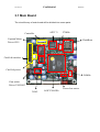
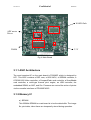
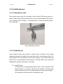
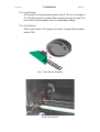
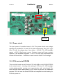
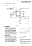
The input power of controller board is 18V. The power circuit uses voltage
regulators to provide15V, 5V and 3.3V for other components. The 13.5V is got
from 15V after the voltage drop of two diodes – 1N4148 . The LED backlight
require a 13.6V--19mA power source. Constant current will keep constant
lightness. The adjustable regulator – LD1117 can fulfil this requirement and
another NPN transistor – 2N3904 are used to switch ON/OFF the backlight.
3.2.2 CPU and serial EPROM
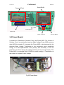
This controller board uses a 80-series CPU with 4KB on-chip FLASH EPROM
to do central control -- including initial setting of LCD driver IC, LED backlight
control, button-pushed sensing and communication with main board. The
serial EPROM stores setting data of LCD which is got from the calibration
process. CPU will read the serial EPROM and complete the initial setting for
LCD after power on.