1
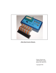
Viper 1, and Extended BASIC, User's Manual
Preliminary Edition
ALTERNATIVE ENGINEERING CORPORATION
P. O. Box 128
GARDINER, MAINE 04345
VIPER is a Registered A.E. Trademark 1981
Bally Computer and Arcade is a Bally Trademark
Viper 1, and Extended BASIC, User's Manual - Preliminary Edition
Version 1.1 - Released Oct 15, 2000
This document has been retyped and converted to PDF format courtesy of the Bally Alley newsletter. For other reprints and more
information visit: http://www.ballyalley.com Corrections? Suggestions? Email Adam Trionfo at: [email protected]
The Viper 1 is more than a 16K memory add-on.
The Viper 1 has been totally designed to help the user get the most out of his/her Bally
Computer/Arcade.
The Viper 1 features are listed as follows:
1.
Programmable Write Protect/Write Enable Front Panel Switch.
2.
Automatic Write Enable/Write Protect Circuit.
3
8K/24K Front Panel RAM Addressing Switch.
4.
Built-in Power Supplies + or -5 + or -12.
5.
Illuminated on/off Switch and Front Panel DC LED Power Indicator.
6.
Viper Keyboard Power Interface.
7.
Switched AC Outlet.
8.
Viper to Bally Interfaced Card, Plus 50 pin Bus Cable.
9.
Heavy Duty Custom-made Aluminum Cabinet.
Viper 1, and Extended BASIC, User's Manual - Page 1 of 13
PROGRAMMABLE WRITE PROTECT/WRITE ENABLE CIRCUIT:
The Programmable Write Protect Circuit enables the user to protect the entire 16K of
memory from being accidentally erased if your program causes the computer to crash. This
saves time in not having to reload the extended memory because it will not have been erased
(Power failure or holding the reset button down for too long will cause a loss of memory). With
this feature, you can remove the Bally BASIC cartridge, play some games, then stick Bally
BASIC back in and continue programming where you left off, without having to reload extended
BASIC because the data will remain intact. To use, set the Auto Write/Programmable Write
switch in the Programmable position, then enter &(192)=0, this command will allow you to enter
data to the RAM. To protect it (convert RAM to ROM) simply enter &(64)=0. Now the RAM is
protected from being accidentally or otherwise changed or lost.
Example: Set the 8K/24K switch in 24K position.
Program
Comments
&(192)=0
Write enable.
%(24576)=32767
Poke 32767 into first extended memory address.
Print %(24576)
Test to see if it has been written to our 32767.
Now that the number is in our first extended memory address, turn off the
Write Enable.
&(64)=0
Write Protect the RAM.
%(24576)=0
Try to change the value in the memory to zero.
Print %(24576)
Verify that it did not change to 0 but is still 32767.
Viper 1, and Extended BASIC, User's Manual - Page 2 of 13
This quick program will help to familiarize you with this feature and also verify the
proper operation of the Viper System.
LOADING EXTENDED BASIC FROM TAPE:
The auto write protect switch position is primarily designed to implement the use of Jay
Fenton's excellent Extended BASIC, which is included free with every Viper 1. The language
occupies the first 8K of RAM Space. This will leave you approximately 8K of programming
RAM minus approximately 1K of RAM for the BASIC to use as stack and scratch pad. Since
the language is loaded from tape, it is possible that not every tape recorder will load properly due
to poor tape head alignment on the low-end priced recorders. It is strongly recommended that a
quality tape recorder be used when loading the language to insure proper operation. A checksum
program is included to verify if your load was 100% correct or not. Once you have verified a
perfect load you then must make a copy of it onto your regular tape recorder so you will have a
compatible copy for your regular recorder.
To use:
Set the 8K/24K switch to 24K, then with your regular Bally BASIC, load the tape as if it
were any program : input/go.
The tape will take approximately 7-8 minutes to load, at the end of the load it will print
out (load done, throw write switch to Auto Write Protect Position), then press the go key to jump
to the Extended BASIC. If the load was at least partially successful, the screen should clear, and
then print in the new small character font "Extended Basic 1.0"
If the Extended BASIC comes up, the next thing you should do is enter the checksum
program to verify that all of the 8K has loaded correctly so as to avoid any crashes while using it
(checksum program is at end of this manual). After running the checksum program, if you
discover any errors, reload the entire language. If you get a perfect load, you should make a
copy of the language on your tape recorder.
COPY EXTENDED BASIC FROM MEMORY TO TAPE:
To make a copy of Extended BASIC, simply rewind the tape with Extended BASIC on it
to the beginning. Then press : input (you should be running Extended BASIC when you do this).
Viper 1, and Extended BASIC, User's Manual - Page 3 of 13
Load program until you see it print Run statement. Run is the last word you will see appear on
the screen, then stop the tape.
Press the go key on the key Pad, then type in Go to 100. Now before hitting the go key,
take out the Extended BASIC tape and put in your own tape (your own tape must be at least a
C-30 or it will not hold the entire program). Set your recorder to Record and wait 4-5 seconds,
then hit the Go key. The program will then list itself and the 8K language to your tape recorder
(you will see garbage printed at the bottom of the screen; this is actually the program loading out
to your tape). When the copy to tape is completed, it will clear the screen and print the word
DONE! You should now have a copy of Extend BASIC made for your own recorder and should
have no further compatibility problems when reloading the language from tape.
Viper 1, and Extended BASIC, User's Manual - Page 4 of 13
AUTO WRITE SWITCH:
The reason you must use the Auto Write Switch position with the Extended BASIC
running is because 1/2 of the RAM is being used to store the new BASIC language and the other
half is being used by you to write programs in. Because of this, you must be able to write to the
upper 8K of memory, but still protect the lower 8K. If the lower 8K was ever written into, you'd
destroy the memory containing the Extended BASIC. The Auto Write Circuit is designed to
check to see what area of memory you are in, and then automatically turn on and off the Write
Protect/Write Enable Circuit. Whenever the memory address is using Extended BASIC, it will
protect it from accidentally being written over. Then when the address is above the limits of the
language, it allows you to write it to memory so you can write programs in Extended BASIC.
Viper 1, and Extended BASIC, User's Manual - Page 5 of 13
VIPER INTERNAL DUAL SWITCHPAKS FOR MEMORY ADDRESSING AND BUS
CONTROLS
Switchpak #2
#1 and #2 switches are the extended memory addressing control lines. Switches #1 and
#2 should never be on at the same time. Unless you are using the System 5 with its
extended memory addressing capabilities switch, #1 switch should always be off and
switch #2 should always be on.
Switch #3 is used to modify the addressing values of Switchpak #1 by 4K increments.
Switch #4 is a signal called System-Enable. The Viper must disable this signal in order
to use the Bally bus to communicate with the Z-80 microprocessor inside.
Switch #5 is called Buzzoff. This signal must also be used to control the Viper to Bally
bus signals.
Switch #6 is the Cassette enable signal. This is used to enable or disable the cassette
cartridge slot when using the Viper 1.
Switch #7 is the 7 meg. clock signal from the Bally bus. This clock is used to control the
Viper RAM operation timing.
Switch #8 is used for changing the clock to the RAM from external (the Bally clock) to
the internal Crystal Y1. Y1 is optional and is not included with the system.
Viper 1, and Extended BASIC, User's Manual - Page 6 of 13
VIPER KEYBOARD INTERFACE
Built onto the system 1 interface card is a serial to parallel ASCII keyboard interface for
the Viper keyboard. This keyboard has 61 keys and is ASCII encoded. The Viper keyboard jack
is on the back panel of the Viper cabinet and is marked "keyboard."
VIPER TO BALLY INTERFACE CARD
The Viper to Bally Interface card is an integral part of the Viper 1 system. This board
contains the power supplies for the RAM Card and the Viper Keyboard. The 50 pin bus cable
from the Bally is connected to this board at one end, and at the other end is the Viper 44 pin bus
connector. All power supplies +5, -5, +12, -12, are generated on this board and include input
and output filtering. Serial to parallel conversion for the Viper Keyboard is also performed on
this board.
Viper 1, and Extended BASIC, User's Manual - Page 7 of 13
SWITCHED AC OUTLET
The switched AC outlet is to be used for the Bally wall transformer only. Simply plug
your Bally wall transformer into the AC outlet on the rear of the Viper. Then set the on/off
switch on the back of the Bally to on and leave it there from now on. The Viper front panel
illuminated on/off switch will turn on the Bally when you power up the Viper. It may be
necessary for you to press the reset button on the Bally after you power up the system. When
you turn off the Viper, you will also be turning off the Bally because the outlet on the back is
switched on and off with the Viper power switch, hence the name "switched outlet."
Viper 1, and Extended BASIC, User's Manual - Page 8 of 13
CHECKSUM PROGRAM
This program is used to verify that the entire language has been successfully loaded from
tape to your Viper memory. This program calculates the sum of each byte in 128 byte blocks.
Once you have loaded the language you should verify that the checksum values match the listing
below. If any of the values don't match the listed values, then there is a mistake in the language.
You should reload the entire language from tape and try the checksum program again.
Once you have a perfect copy it is strongly recommended that you immediately make an extra
copy or two for your future use.
CHECKSUM PROGRAM LISTING
10
20
30
40
50
60
70
80
90
For a=24576 to 32767 step 127
C=0
For B=a to a+127
%(20002)=% (B)
%(20003)=0
C=C+%(20002)
Next B
Print "Checksum for Block starting at ",a," is "C
Next a
LISTING:
13299
12679
14161
9282
15383
14974
16565
13702
14948
14160
16079
17987
16912
15182
10634
16824
15272
14026
16020
17526
16361
11948
16291
15225
16006
15724
14333
16196
15385
16429
15613
15847
16392
14853
16662
15056
13379
15645
15091
16558
17565
17628
16185
14211
11936
20768
13965
14487
13744
11831
13409
13150
15524
14784
16099
14543
3943
6962
0
0
0
0
0
Note: There is a handwritten note here that says, "These values are not valid. Use side II of Ext.
BAS for new checksum values."
Viper 1, and Extended BASIC, User's Manual - Page 9 of 13
COPY CARTRIDGE PROGRAM
10
: INPUT ; FOR I = 24576 TO 28672; %(I) = KP; NEXT I
50
: RETURN ; PRINT "1-SWITCH TO AUTO WRITE,"
52
PRINT "2-REMOVE BASIC CARTRIDGE,"
54
PRINT "3-THROW SWITCH TO 8K"
58
PRINT "PRESS RESET TO PLAY!"
60
STOP
100
CLEAR ; : PRINT; LIST; PRINT "RUN"; FOR I = 1 TO 2000;
NEXT I; C+=-46; N+=0
110
FOR I = 8192 TO 12288; TV=%(I); NEXT I : RETURN
150
: RETURN; DEFAULT; CLEAR; PRINT "DONE"
Viper 1, and Extended BASIC, User's Manual - Page 10 of 13
TROUBLES:
The Viper must be plugged into a three prong grounded outlet for proper operation.
If the language did not load properly, check the followings:
The Write Protect switch should be in the programmable position while the tape is
loading. After the load is done you then throw the switch to the Auto Write position.
If the tape never returned with the final statements (load done/switch to auto write, hit
go) then it was a bad tape load. Try the volume and set the tone all the way treble. If the tape
won't load after several attempts, then you must try a higher quality tape recorder. All tapes that
we include will have been tested for proper operation.
The Viper memory is made with 16K Dynamic Rams. This type of memory requires
constant refreshing to prevent it from losing its contents. Because of this, it is not recommended
to hold down the reset button on the Bally for more than a brief second or two in order to prevent
erasing of the memory. Whenever this reset button is pressed, it will stop the refreshing signals
to the memory.
Any persons adding length to the original Viper bus cable will be in violation of FCC
rules and regulations. By lengthening the cable you will increase the radiated noise factor of the
unit and may cause excess interference to nearby electronic equipment.
Viper 1, and Extended BASIC, User's Manual - Page 11 of 13
INSTALLATION
Power all units off.
Installation of the Viper 1 system to the Bally Computer/Arcade.
Knock out the plastic cover in the center of the rear of the machine. The piece is between
the two joysticks on the left and the two on the right.
Using a screwdriver, slip it in the opening and pry outwards the plastic knockout. This
should snap out and expose the Bally 50 pin bus connector.
To insert the Viper bus cable you will have to hold down the Bally cardboard insert that
will be just below the bus opening. Then plug in the 50 pin Viper bus cable. Do not
twist the cable when installing it. The cable should go straight up and into the Bally bus
opening.
GLOSSARY OF COMPUTER TERMS
Write Protect
Prevents the RAM from being erased.
Write Enable
Enables the RAM to store information.
RAM
Read and write memory.
ROM
Read only memory.
16K
16 thousand bytes of memory, 1 character per byte.
Byte
A byte is the name used to describe RAM. There are 8 data bits to 1 byte.
Viper 1, and Extended BASIC, User's Manual - Page 12 of 13
THE LIMITED WARRANTY APPLIES TO THE VIPER 1 AND THE FREE EXTENDED
BASIC ON TAPE
Alternative Engineering Corporation, P.O. Box 128, Gardiner, Maine, 04345 hereby
warrants to the original purchaser only, that this product will be free from defects in materials
and workmanship, under normal use for a period of 90 days from the date of purchase.
The Warrantor shall have no liability or responsibility to purchaser or any other person or
entity with respect to any liability, loss or damage caused or alleged to be caused directly or
indirectly by this product, including but not limited to any interruption of service, loss of
business and anticipatory profits or consequential damages resulting from the use or operation of
this product.
If during this 90-day period a defect in this product should occur, the product may be
returned to Alternative Engineering Corporation or to an authorized dealer and Alternative
Engineering Corporation will repair this product without charge.
When requesting performance under the terms of this warranty, the original purchase
date must be established by the customer by means of a bill of sale, invoice, or other acceptable
documentation.
This warranty gives you specific legal rights, and you may also have other rights which
vary from state to state.
Some states do not allow the exclusion or limitation of incidental or consequential
damages so the above limitations or exclusions may not apply to you.
Viper 1, and Extended BASIC, User's Manual - Page 13 of 13