1
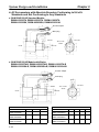
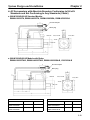
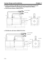
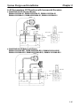
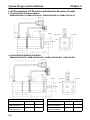
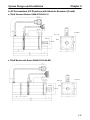
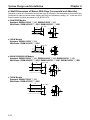
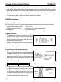
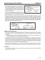
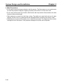
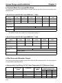
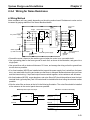
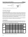
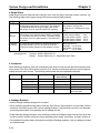
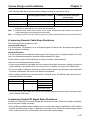
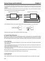
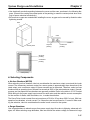
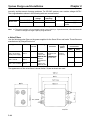
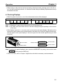
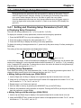
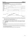
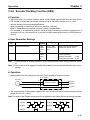
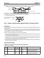
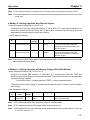
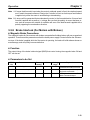
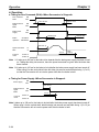
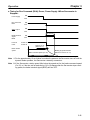
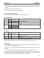
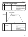
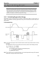
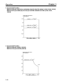
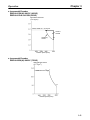
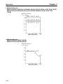
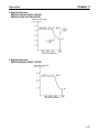
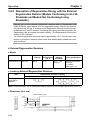
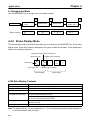
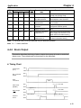
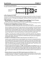
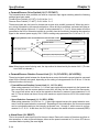
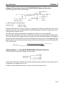
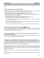
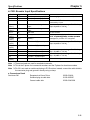
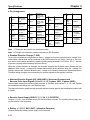
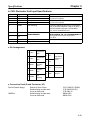
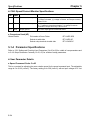
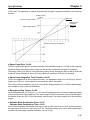
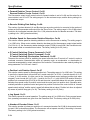
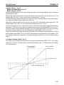
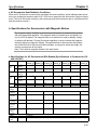
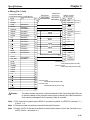
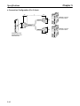
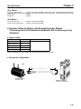
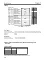
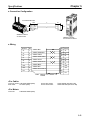
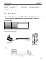
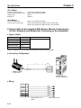
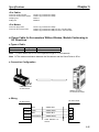
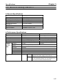
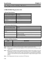
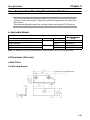
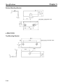
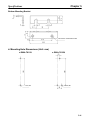
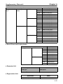
Chapter 5
Specifications
D Sensor ON Input/Input Ground (5/6: SEN/SENGND) (Absolute Encoders)
The SEN signal input circuit is shown below.
Servo Driver Side
+5 V
High: Approx. 1 mA
0V
Equivalent to 7406
0V
• A PNP transistor is recommended.
• Signal Levels
High: 4 V min.
Low: 0.7 V max.
When the SEN signal turns ON (low to high), 5 V is supplied to the absolute encoder. When power is not
supplied to the motor (Run command input OFF) and the SEN signal is turned OFF (high to low), the 5 V
to the absolute encoder is cut off.
The SEN signal is ignored while power is supplied to the motor even if it is turned OFF.
Power cannot be supplied to the motor even if the Run command is received unless the SEN signal is
ON. Power will also not be supplied to the motor between the time that the SEN signal turns ON and the
encoder achieves normal operation even if the Run command is received. Do not turn ON the SEN signal for at least 3 s after turning on the power supply. Refer to the chart below to turn the SEN signal ON,
OFF, and ON again.
SEN signal
1.3 s min.
15 ms min.
D Backup Battery +/– Input (28/29: BAT/BATGND) (Absolute Encoders)
The backup battery connection diagram is shown below.
Backup battery
2.8 to 4.5 V
These are the connection terminals for the battery that backs up the absolute encoder when power is
not supplied. The voltage is 2.8 to 4.5 V.
A battery is not provided with the motor or drives. The user must provide one.
5-15