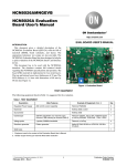
1
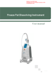
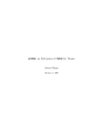
Error and Maintenance This chapter explains the items to check when problems occur, error diagnosis using the alarm LED display and measures, error diagnosis based on the operating condition and measures, and periodic maintenance. 11-1 Error Processing.........................................................11-2 Preliminary Checks When a Problem Occurs............................... 11-2 Precautions When a Problem Occurs........................................... 11-3 Replacing the Servomotor and Servo Drive.................................. 11-4 11-2 Warning List ................................................................11-5 11-3 Alarm List ....................................................................11-6 11-4 Troubleshooting .......................................................11-11 Error Diagnosis Using the Alarm Displays .................................. 11-11 Error Diagnosis Using the Operation Status ............................... 11-18 11-5 Periodic Maintenance...............................................11-22 Servomotor Limit......................................................................... 11-22 Servo Drive Limit......................................................................... 11-23 Replacing the Absolute Encoder Battery .................................... 11-24 11 Accurax G5 AC SERVOMOTOR AND SERVO DRIVE USER'S MANUAL 11-1 Error Processing 11-1 Error Processing Preliminary Checks When a Problem Occurs This section explains the preliminary checks and analytical softwares required to determine the cause of a problem if one occurs. Checking the Power Supply Voltage Check the voltage at the power supply input terminals. Main circuit power supply input terminal (L1, L2, L3) R88D-KTxL (50 to 400 W) : Single-phase 100 to 115 VAC (85 to 127 V) 50/60 Hz R88D-KTxH (100 W to 1.5 kW) : Single-phase 200 to 240 VAC (170 to 264 V) 50/60 Hz (750 W to 1.5 kW) : 3-phase 200 to 240 VAC (170 to 264 V) 50/60 Hz (2 to 15 kW) : 3-phase 200 to 230 VAC (170 to 253 V) 50/60 Hz R88D-KTxF (750 W to 15 kW) : 3-phase 380 to 480 VAC (323 to 528 V) 50/60 Hz Control circuit power supply input terminal (L1C, L2C) R88D-KTxL (50 to 400 W) : Single-phase 100 to 115 VAC (85 to 127 V) 50/60 Hz R88D-KTxH (100 W to 1.5 kW) : Single-phase 200 to 240 VAC (170 to 264 V) 50/60 Hz (2 to 15 kW) : Single-phase 200 to 230 VAC (170 to 253 V) 50/60 Hz R88D-KTxF (750 W to 15 kW) : 24 VDC (21.6 to 26.4 V) If the voltage is out of this range, there is a risk of operation failure, so be sure that the power supply is correct. Check the voltage of the sequence input power supply. (+24 VIN terminal (CN1 pin 7)) Within the range of 11 to 25 VDC. If the voltage is out of this range, there is a risk of operation failure. Be sure that the power supply is correct. Checking Whether an Alarm Has Occurred Make an analysis using the 7-segment LED display area in the front of the driver and using the Operation keys. When an alarm has occurred Check the alarm display that is displayed (xx) and make an analysis based on the alarm that is indicated. 11 Error and Maintenance When an alarm has not occurred Make an analysis according to the error conditions. In either case, refer to "11-4 Troubleshooting" (P.11-11) for details. 11-2 Accurax G5 AC SERVOMOTOR AND SERVO DRIVE USER'S MANUAL 11-1 Error Processing Precautions When a Problem Occurs When checking and verifying I/O after a problem has occurred, the driver may suddenly start to operate or suddenly stop, so always take the following precautions. You should assure that anything not described in this manual is not possible with this product. Precautions Disconnect the wire before checking for cable breakage. Even if you test conduction with the cable connected, test results may not be accurate due to conduction via bypassing circuit. If the encoder signal is lost, the motor may run away, or an error may occur. Be sure to disconnect the motor from the mechanical system before checking the encoder signal. When measuring the encoder output, perform the measurement based on the SENGND (CN1 pin 13). When an oscilloscope is used for measurement, it will not be affected by noise if measurements are performed using the differential between CH1 and CH2. When performing tests, first check that there are no persons in the vicinity of the equipment, and that the equipment will not be damaged even if the motor runs away. Before performing the tests, verify that you can immediately stop the machine using an immediate stop even if it runs away. 11 Error and Maintenance Accurax G5 AC SERVOMOTOR AND SERVO DRIVE USER'S MANUAL 11-3 11-1 Error Processing Replacing the Servomotor and Servo Drive Use the following procedure to replace the Servomotor or Servo Drive. Replacing the Servomotor 1. Replace the motor. 2. Perform origin adjustment (for position control). When the motor is replaced, the motor's origin position (phase Z) may deviate, so origin adjustment must be performed. Refer to the Position Controller's manual for details on performing origin adjustment. 3. Set up the absolute encoder. If a motor with an absolute encoder is used, the absolute value data in the absolute encoder will be cleared when the motor is replaced, so setup is again required. The multi-rotation data will be different from before it was replaced, so reset the initial Motion Control Unit parameters. For details, refer to "Absolute Encoder Setup"(P.9-5). Replacing the Servo Drive 1. Copy the parameters. Use the Operation keys on the driver to write down all the contents of parameter settings. 2. Replace the driver. 3. Set the parameters. Use the Operation keys on the driver to set all the parameters. 4. Set up the absolute encoder. If a motor with an absolute encoder is used, the absolute value data in the absolute encoder will be cleared when the driver is replaced, so setup is again required. The multi-rotation data will be different from before it was replaced, so reset the initial Motion Control Unit parameters. For details, refer to "Absolute Encoder Setup"(P.9-5). Error and Maintenance 11 11-4 Accurax G5 AC SERVOMOTOR AND SERVO DRIVE USER'S MANUAL 11-2 Warning List 11-2 Warning List This is a function to output a warning signal before the protective function operates to notify the overload and other statuses in advance. Set the warning output type to Warning Output Selection 1 (Pn440) and Waning Output Selection 2 (Pn441). Precautions for Correct Use Each warning automatically returns to the status before it occurred once the system recovers from the error. However, for the time set in the Warning Latch Hold Time Selection (Pn627), the warning status will be held. To clear the warning during the latch hold time, do so by performing the same procedures as alarm clear. Warning List Warning number Latch*1 Warning name Warning occurrence Warning Output Selection Warning Mask condition (Pn440, Pn441) *2 Setting (Pn638) A0 Overload warning The load ratio is 85% or 1 more of the protection level. bit 7 A1 Excessive regeneration warning The regeneration load ratio is 85% or more of the protection level. 2 bit 5 Always Battery voltage is 3.2 V fixed with or less. no time limit 3 bit 0 Battery warning A2 A3 A4 Fan warning Encoder communications warning The fan stop status continues for 1 s. 4 bit 6 The number of continuous occurrences of encoder communications error exceeded the specified value. 5 bit 4 The encoder detects the overheating warning. 6 bit 3 A5 Encoder overheating warning A6 Vibration detection warning 7 bit 9 Limit detection warning Always The limit of the capacitor fixed with or the fan is below the no time limit specified value. 8 bit 2 External scale error warning The external scale detected a warning. 9 bit 8 The number of occurrences of external scale communications error exceeded the specified value. 10 bit 10 A8 A9 External scale communications warning *1. The "" fields can be set to 1 to 10 s in the Warning Latch Hold Time Selection (Pn627) or to the notime limit setting. However, the battery warning is fixed with no time limit. *2. Select the type of warning to be output in warning output 1 (WARN1) and warning output 2 (WARN2) in the Warning Output Selection 1 (Pn440) and Warning Output Selection 2 (Pn441).If you set this to 0, all warning types will be output.Do not set it to a value other than above. *3. Each warning detection can be masked using the Warning Mask Setting (Pn638).The table shows the corresponding bits. The warning detection is masked when the bit = 1. Accurax G5 AC SERVOMOTOR AND SERVO DRIVE USER'S MANUAL 11-5 Error and Maintenance A7 11 Vibration is detected. 11-3 Alarm List 11-3 Alarm List If the driver detects an error, the alarm output (ALM) will turn ON, the power drive circuit in the driver will turn OFF, and the alarm code will be displayed. Precautions for Correct Use Refer to "Error Diagnosis Using the Alarm Displays"(P.11-11) for appropriate alarm measures. Release the alarm using one of the following methods. Remove the cause of the alarm first. · Input the alarm reset input (RESET) signal. · Turn OFF the power supply, then turn it ON again. · Execute the alarm reset on the Parameter Unit. However, some alarms can only be reset by turning the power supply OFF then ON again. Refer to the next item "Alarm List". If you release an alarm while the operation command (RUN) is turned ON, the Servo Drive will start operation as soon as the alarm is released, which is dangerous. Be sure to turn OFF the RUN before clearing the alarm. If the RUN is always ON, first check safety sufficiently before clearing the alarm. When an alarm occurs, the servodrive latches the status of the servodrive just before the alarm occurence. Those latched values can be read with the software tool for diagnostics. Refer to the CX-Drive for details. The stop mode in case of an alarm may vary depending on the „Immediate stop“ attribute in each alarm. Error and Maintenance 11 11-6 Accurax G5 AC SERVOMOTOR AND SERVO DRIVE USER'S MANUAL 11-3 Alarm List Alarm List Error number Attribute Error detection function Main Sub 11 0 12 0 Detection details and probable cause History Can be Immediate cleared stop *1 Control power supply undervoltage The DC voltage of the main circuit fell below the specified value while the operation command (RUN) input was ON. Overvoltage The DC voltage in the main circuit is abnormally high. 0 Main power supply undervoltage (Insufficient voltage between P and N) The DC voltage of the main circuit is low. 1 Main power supply undervoltage (AC cut-off detection) A location was detected where the main circuit AC power supply is cut off. 0 Overcurrent Overcurrent flowed to the IGBT. 1 IPM error Motor power line ground fault or short circuit. Driver overheat The temperature of the driver radiator exceeded the specified value. Overload Operation was performed with torque significantly exceeding the rating for several seconds to several tens of seconds. The regenerative energy exceeds the processing capacity of the Regeneration Resistor. Regeneration Tr error An error was detected in a driver regeneration drive Tr. 0 Encoder communications disconnection error The encoder wiring is disconnected. 1 Encoder communications error An encoder communications error was detected. 23 0 Encoder communications data error Communications cannot be performed between the encoder and the driver. Error counter overflow 24 0 The error counter accumulated pulse exceeds the set value for the Error Counter Overflow Level (Pn014). During full closing control, difference between position of load from external scale and position of motor due to encoder was larger than the pulse number set by Excessive Hybrid Error Setting (Pn332). Overspeed The motor rotation speed exceeded the set value of the Overspeed Level set (Pn513). Overspeed 2 The motor rotation speed exceeded the set value of the Overspeed Level set 2 (Pn615). Command pulse A command pulse frequency error was detected. Pulse regeneration error The pulse regeneration output frequency exceeded the limit. 13 14 15 0 16 0 Regeneration overload 0 18 1 21 25 0 0 26 1 27 0 28 0 Accurax G5 AC SERVOMOTOR AND SERVO DRIVE USER'S MANUAL 11-7 Error and Maintenance Excessive hybrid error 11 11-3 Alarm List Error number Attribute Error detection function Main Sub 29 0 30 0 History Error counter overflow Safety input error Safety input signal turned OFF. 0 Interface input duplicate allocation error 1 A duplicate setting for the interface input signals was detected. 1 Interface input duplicate allocation error 2 2 Interface input function number error 1 3 Interface input function number error 2 4 Interface output function number error 1 An undefined number was detected in the interface output signal allocations. 5 Interface output function number error 2 6 Counter reset allocation error The counter reset function was allocated to something other than input signal SI7. 7 Command pulse prohibition input allocation error The command pulse prohibition input function was allocated to something other than input signal SI10. Overrun limit error The motor exceeded the allowable operating range set in the Overrun Limit Setting (Pn514) with respect to the position command input. Data in the Parameter Save area was corrupted when the power supply was turned ON and data was read from the EEPROM. The checksum for the data read from the EEPROM when the power supply was turned ON does not match. Drive prohibition input error The forward drive prohibition and reverse drive prohibition inputs are both turned OFF. Excessive analog input 1 A current exceeding the Speed Command/Torque Command Input Overflow Level Setting (Pn424, Pn427 or Pn430) was applied to the analog command input (pin 14). The voltage supplied to the absolute encoder is lower than the specified value. The multi-rotation counter of the absolute encoder exceeds the specified value. The motor rotation speed exceeds the specified value when only the battery power supply of the absolute encoder is used. Error and Maintenance 34 0 36 0 to 2 37 0 to 2 38 0 0 39 1 2 Parameter error Parameters destruction Excessive analog input 2 40 0 41 0 42 0 An undefined number was detected in the interface input signal allocations. Excessive analog input 3 Absolute encoder system down error ABS Absolute encoder counter 11-8 Can be Immediate cleared stop *1 Error counter value based on the encoder pulse reference exceeded 229 (536,870,912). 33 11 Detection details and probable cause overflow error ABS Absolute encoder overspeed error ABS Accurax G5 AC SERVOMOTOR AND SERVO DRIVE USER'S MANUAL 11-3 Alarm List Error number Attribute Error detection function Main Sub 43 0 44 Detection details and probable cause History Encoder initialization error protection An encoder initialization error was detected. Absolute encoder 1rotation counter error A 1-turn counter error was detected. Can be Immediate cleared stop *1 A multi-rotation counter error or phase-AB signal error was detected. Absolute encoder status error ABS The rotation of the absolute encoder is higher than the specified value. Encoder phase-Z error A serial incremental encoder phase Z pulse irregularity was detected. Encoder CS signal error A logic error was detected in the CS signal for serial incremental encoder. 0 External scale connection error An error was detected in external scale connection. 1 External scale An error was detected in external communications data error scale communications data. 1 External scale status error 0 An external scale error code was detected. External scale status error 1 2 External scale status error 2 3 External scale status error 3 4 External scale status error 4 5 External scale status error 5 0 ABS 45 0 Absolute encoder multirotation counter error ABS 47 0 48 0 49 0 50 0 51 0 55 1 87 95 0 0 An error was detected in the external scale phase A connection. Phase-B connection error An error was detected in the external scale phase B connection. Phase-Z connection error An error was detected in the external scale phase Z connection. Forced alarm input error The forced alarm input signal was input. Motor non-conformity The combination of the Servomotor and Servo Drive is not appropriate. The encoder was not connected when the power supply was turned ON. *1. An immediate stop means an error causing an immediate stop when the Pn510 "Stop Selection for Alarm Generation" is set to 4 to 7. For details, refer to "Stop Selection for Alarm Generation"(P.8-50). Accurax G5 AC SERVOMOTOR AND SERVO DRIVE USER'S MANUAL 11-9 11 Error and Maintenance 2 Phase-A connection error 11-3 Alarm List Extended Alarms Error No. Error detection function Detection details and probable cause Main Sub 46 0 Absolute Error Absolute encoder status is abnormal 51 6 External Scale Error External scale status is abnormal 0 U-Phase Phase Current Detection Error U-Phase Current Detection Value is abnormal when objecting servo off to servo on 1 W-Phase Phase Current Detection Error W-Phase Current Detection Value is abnormal when objecting servo off to servo on 2 Current Detection Syste Error Setting value of Current Detection Systemu is abnormal 0 AI2 Input Error Analog Input Voltage 2 value is abnormal +11 V over is lasting 200 ms 1 AI3Input Error Analog Input Voltage 3 value is abnormal +11 V over is lasting 200 ms 72 0 Thermal Error Hardware is abnormal 73 0 VDC Detection System Error Hardware is abnormal 0 Internal RAM Error Microcomputer is abnormal 1 Internal ROM Error Internal ROM is abnormal 77 0 Stacke Error Lack of Stack Area 78 0 Encoder EEPROM Error Encoder EEPROM Check is abnormal 96 0 LSI Initialization Error Falut of MNM1223 initialization 97 0 Setting Error Encoder type and control mode are unmatching 99 0 Hardware Error Power curcuit detects the something hardware error 99 1 Encoder Setting Error Encoder Setting is not correct 70 71 76 Error and Maintenance 11 11-10 Accurax G5 AC SERVOMOTOR AND SERVO DRIVE USER'S MANUAL 11-4 Troubleshooting 11-4 Troubleshooting If an error occurs in the machine, determine the error conditions from the alarm displays and operation status, identify the cause of the error, and take appropriate measures. Error Diagnosis Using the Alarm Displays Alarm display 11 Error conditions Power supply undervoltage Status when error occurs Occurs when the servo is turned ON. Occurs when the power supply is turned ON. Cause · Increase the power supply capacity. · Change the power supply. · Turn ON the power supply. · Power supply capacity is insufficient. · Increase the power supply capacity. · Phase loss · Connect the phases (L1, L2, L3) of the power supply voltage correctly. · For single-phase, connect to L1 and L3 correctly. · The main circuit power supply is damaged. · Control PCB error. · Replace the driver. · Main circuit power supply voltage is out of allowable range. · Change the main circuit power supply voltage to within allowable range. · Load inertia is too large. · Calculate the regenerative energy and connect an External Regeneration Resistor with the required regeneration absorption capacity. · Extend the deceleration time. Overvoltage · Main circuit power supply voltage is out of allowable range. · Change the main circuit power supply voltage to within allowable range. · Gravitational torque is too large. · Add a counterbalance to the machine to lower gravitational torque. · Reduce the descent speed. · Calculate the regenerative energy and connect an External Regeneration Resistor with the required regeneration absorption capacity. Occurs during descent (vertical axis). Accurax G5 AC SERVOMOTOR AND SERVO DRIVE USER'S MANUAL 11-11 11 Error and Maintenance · The power supply voltage is low. · Momentary power interruption occurred. · Power supply capacity is insufficient. · The power supply voltage is reduced because the main power supply is OFF. · The main power supply is not input. Occurs when the motor is decelerating. 12 Measures 11-4 Troubleshooting Alarm display 13 Error conditions Status when error occurs Cause Measures Occurs when the servo is turned ON. · The power supply voltage is low. · Momentary power interruption occurred. · Power supply capacity is insufficient. · The power supply voltage is reduced because the main power supply is OFF. · The main power supply is not input. · Check the power supply capacity. · Change the power supply. · Turn ON the power supply. · Extend the Momentary Hold Time (Pn509). Main circuit power supply undervoltage · Correctly connect the phases of the power supply voltage. · Phase loss · Correctly connect the single-phase. Occurs when the power supply is turned ON. · The main circuit power supply is damaged. · Control PCB damage. · Replace the driver. · Control PCB error · Replace the driver. · The motor power line is short-circuited or ground-faulted between phases. · Repair the short-circuited or ground-faulted power line. · Measure the insulation resistance at the motor and, if there is a short circuit, replace the motor. · Phase U, phase V, phase W, and the ground are wired incorrectly. · Wire correctly. · Motor winding is burned out. · Measure the winding resistance, and if the winding is burned out, replace the motor. · The relay for the dynamic brake has been deposited. · Do not frequently input the operation command (RUN) input. · Do not operate the system by turning the servo ON and OFF. · Motor non-conformity · Use a motor that is appropriate for use with the driver. · The pulse input timing is too soon. · Wait at least 100 ms before inputting pulses after turning ON the operation command (RUN). · The resistor in the driver is abnormally overheating. · Reduce the ambient temperature of the driver to 55C or lower. · If the relay does not click when the power supply is turned ON, replace the driver. 11 Error and Maintenance 14 11-12 Overcurrent Occurs when the servo is turned ON. Accurax G5 AC SERVOMOTOR AND SERVO DRIVE USER'S MANUAL 11-4 Troubleshooting Alarm display 15 Error conditions Driver overheat Status when error occurs Occurs during operation. Occurs when the servo is turned ON. 16 · The ambient temperature is too high. · The load is too large. Measures · Lower the ambient temperature. · Increase the capacity of the driver and motor. · Reduce the load. · Extend the acceleration/ deceleration times. · There is an error in the · Wire the motor power motor wiring (the wiring or cable correctly. the connections are faulty). · The electromagnetic brake is ON. · Turn OFF the brake. · The Servo Drive is faulty. · Replace the driver. · The effective torque · Review the load conditions exceeds the rated torque. and operating conditions. · The initial torque exceeds · Review the motor the maximum torque. capacity. Overload Occurs during operation. Occurs when the motor is decelerating. · Unusual noise or vibration is caused by faulty gain adjustment. · Adjust the gain correctly. · The Servo Drive is faulty. · Replace the driver. · Load inertia is too large. · Calculate the regenerative energy and connect an External Regeneration Resistor with the required regeneration absorption capacity. · Extend the deceleration time. · The deceleration time is too short. · The motor rotation speed is too high. · Reduce the motor rotation speed. · Extend the deceleration time. · Calculate the regenerative energy and connect an External Regeneration Resistor with the required regeneration absorption capacity. · The operating limit of the · Set Pn016 to 2. External Regeneration For details, refer to Resistor is limited to 10% duty. "Parameters Details". Regeneration overload · Gravitational torque is too large. Occurs during descent (vertical axis). · Add a counterbalance to the machine to lower gravitational torque. · Reduce the descent speed. · Calculate the regenerative energy and connect an External Regeneration Resistor with the required regeneration absorption capacity. · The operating limit of the · Set Pn016 to 2. External Regeneration For details, refer to Resistor is limited to 10% duty. "Parameters Details". Accurax G5 AC SERVOMOTOR AND SERVO DRIVE USER'S MANUAL 11-13 11 Error and Maintenance 18 Cause 11-4 Troubleshooting Alarm display 21 Error conditions Encoder communications error Status when error occurs Occurs during operation. Cause Measures · The encoder is disconnected. · Connector contacts are faulty. · Fix the locations that are disconnected. · Wire correctly. · The encoder is wired incorrectly. · Wire correctly. · The encoder is damaged. · Replace the motor. 23 Encoder communications data error Occurs when the power supply is turned ON. Or, occurs during operation. · The driver is faulty. · Replace the driver. · The motor is mechanically held. · If the motor shaft is held, release it. · The encoder signal line is wired incorrectly. · Wire correctly. · Noise on the encoder wiring causes incorrect operation. · Take measures against noise on the encoder wiring. · The encoder power supply voltage has dropped (especially when the cable is long.) · Provide the required encoder power supply voltage (5 VDC 5%). · The motor power line or the encoder wiring is incorrect. · Wire correctly. Occurs when the motor does not rotate even when · The motor is command pulses are mechanically held. input. Occurs during high-speed rotation. 11 24 Error counter overflow · Control PCB error · Replace the driver. · The motor power line or the encoder wiring is incorrect. · Wire correctly. · Gain adjustment is insufficient. · Adjust the gain. Error and Maintenance Occurs when a long string · The acceleration/ of command pulses is deceleration is too rapid. given. 25 11-14 Excessive hybrid deviation error · If the motor shaft is held, release it. · Release the electromagnetic brake. · Extend the acceleration/ deceleration times. · The load is too large. · Reduce the load. · Select a suitable motor. Occurs during operation. · The set value for the Error Counter Overflow Level (Pn014) is exceeded. · Increase the set value of Pn014. · Reduce the rotation speed. · Reduce the load. · Extend the acceleration/ deceleration times. Occurs for full closing control. · There is deviation between the load position according to the external scale and the motor position according to the encoder. · Check the motor and load connection. · Check the external scale and driver connection. · Check the external scale load position and encoder motor position settings. Accurax G5 AC SERVOMOTOR AND SERVO DRIVE USER'S MANUAL 11-4 Troubleshooting Alarm display Error conditions Status when error occurs Cause · The speed command input is too large. 26 Overspeed · The setting for the Electronic Gear Ratio Numerator (Pn009, Pn500 to Pn502) is Occurs during high-speed not appropriate. rotation. · The maximum rotation speed is exceeded due to overshooting. Occurs when torque limit switching function is used. 27 28 Command pulse error Pulse regeneration error Occurs when control signal is input or command is input. Occurs during operation. Measures · Set the command pulse frequency to 500 Kpps max. · Set the electronic gear ratio numerator so that the command pulse frequency is 500 Kpps max. · Adjust the gain. · Reduce the maximum command speed. · Wire correctly. · The set value for the Overspeed Detection Level setting (Pn513) is exceeded. · If torque limit switching function is used, correctly set the allowable operating speed for Pn014. · The command pulse input frequency exceeded the limit. · Check the command pulse input. · Increase the set value of Pn532. · The setting for the Electronic Gear Ratio Numerator (Pn009, Pn500 to Pn502) is not appropriate. · Set the electronic gear ratio numerator so that the command pulse frequency is 500 Kpps max. · The pulse regeneration output frequency exceeded the limit. · Check the set value of Pn011 and Pn503. · Set Pn533 to 0 to disable the function. · Check that the motor rotates according to the position command. · Check on the torque monitor that the output torque is not saturated. · Adjust the gain. · Increase the setting for Pn013 or Pn524 to the maximum. · Wire the encoder correctly. 29 Error counter overflow Occurs during operation. · The error counter value for the encoder pulse reference exceeded 229 (536,870,912). 30 Safety input error Occurs during operation. · Safety input signal turned OFF. · Check the statuses of safety inputs 1 and 2. · There is a duplicate setting in the I/O signal function allocation. · Specify the undefined number with the I/O signal function allocation. · Set the function allocation correctly. · There is a mistake in the counter function allocation. · Allocate to SI7. · There is a mistake in the command pulse prohibition input function allocation. · Allocate to SI10. 33 Interface I/O allocation Occurs when the power error supply is turned ON. Accurax G5 AC SERVOMOTOR AND SERVO DRIVE USER'S MANUAL 11-15 11 Error and Maintenance · The encoder is wired incorrectly. 11-4 Troubleshooting Alarm display Error conditions Status when error occurs Measures · The Overrun Limit Setting (Pn514) was exceeded during operation. · Adjust the gain. · Increase the set value of Pn514. · Set Pn514 to 0 to disable the function. · There are data errors in the parameters that were read. · Reset all parameters. · The driver is faulty. · Replace the driver. Occurs when the power supply is turned ON. · The parameters that were read are corrupt. · Replace the driver. 38 Drive prohibition input error Occurs when the servo is turned ON. Or, occurs during operation. · The forward drive prohibition (POT) input and reverse drive prohibition (NOT) input were both OFF at the same time. · Wire correctly. · Replace the limit sensor. · Check whether the power supply for control is input correctly. · Check whether the setting for Drive Prohibition Input Selection (Pn504) is correct. 39 Excessive analog input 1 Occurs during operation. · The voltage input to pin 14 is too high. · Reduce the input voltage. · Change the value for Pn424, Pn427, and Pn430. 40 Absolute encoder system down error Occurs when the power supply is turned ON. Occurs during operation. · The voltage supplied to the absolute encoder is low. · Set up the absolute encoder. · Connect the battery power supply. Occurs during operation. · The multi-rotation counter of the absolute encoder exceeds the specified value. · Properly set the Operation Switch when Using Absolute Encoder (Pn015). Occurs when the power supply is turned ON. · The motor rotation speed · Reduce the motor exceeds the specified rotation speed and value when the battery supply power. power supply is turned ON. · Check the wiring. · The wiring is incorrect. 34 36 37 Overrun limit error Occurs during operation. Parameter error Occurs when the power supply is turned ON. Parameters destruction ABS 41 Absolute encoder counter overflow error ABS 42 Absolute encoder overspeed error ABS 11 Error and Maintenance Cause 44 Absolute encoder 1-turn Occurs when the power counter error ABS supply is turned ON. · The encoder is faulty. · Replace the Servomotor. 45 Absolute encoder multiOccurs when the power rotation counter error supply is turned ON. · The encoder is faulty. · Replace the Servomotor. 47 Absolute encoder status error ABS · The motor was moving when the power supply was turned ON. · Do not let the motor move when the power supply is turned ON. 48 Encoder phase-Z error Occurs during operation. · A phase Z pulse from the encoder was not detected regularly. · Replace the motor. 49 Encoder PS signal error Occurs during operation. · A logic error was · Replace the motor. detected in the PS signal from the encoder. ABS 11-16 Occurs when the power supply is turned ON. Accurax G5 AC SERVOMOTOR AND SERVO DRIVE USER'S MANUAL 11-4 Troubleshooting Alarm display 50 51 Error conditions External scale communications error External scale status error Status when error occurs Cause Measures · The disconnection detection function was activated because communications between the external scale and driver were interrupted. · Wire correctly. · Fix the locations that are disconnected. · There was a communications error in data from external scale. · Provide the required external scale power supply voltage. · Wire correctly. · Connect the shield to FG. Occurs during operation. · An external scale error code was detected. · Check the external scale specifications. · From the front panel, clear the external scale error, then turn the power supply OFF, then ON again. · Check the connection. Occurs during operation. 55 Phases-A, B and Z connection error Occurs during operation. · A disconnection or other error was detected in external scale phase A, phase B, or phase Z connection. 87 Forced alarm input error Occurs during operation. · The forced alarm input signal was input. · Turn OFF the EMGSTOP signal. · The motor and driver combination is incorrect. · Use a correct combination. · The encoder wiring is disconnected. · Wire the encoder wiring. · Fix the locations that are disconnected. 95 Motor non-conformity Occurs when the power supply is turned ON. 11 Error and Maintenance Accurax G5 AC SERVOMOTOR AND SERVO DRIVE USER'S MANUAL 11-17 11-4 Troubleshooting Error Diagnosis Using the Operation Status Symptom Probable cause Items to check Measures The PWR LED The power supply cable is indicator does not wired incorrectly. light when the power supply is turned ON. Check whether the power supply input is within the allowed power supply voltage range. Supply the correct power supply voltage. Check whether the power supply input is wired correctly. Wire correctly. The motor does not rotate even if commands are input from the controller. (Continued on next page) In MONITOR mode, check whether the RUN signal is ON or OFF. The operation command (RUN) is OFF. The forward drive prohibition In MONITOR mode, check whether (POT) and reverse drive the POT signal and NOT signal are prohibition (NOT) are OFF. ON or OFF. The CONTROL mode is not Check the CONTROL mode correct. Selection (Pn001). The error counter reset (ECRST) is ON. In MONITOR mode, check whether the ECRST signal is ON or OFF. The COMMAND PULSE mode (Pn007) selection is incorrect. Check the controller's command pulse type and the Servo Drive's command pulse type. The zero speed designation In MONITOR mode, check whether (VZERO) is OFF. the VZERO signal is ON or OFF. · Turn ON the operation command (RUN). · Wire correctly. · Turn ON the POT and NOT signals. · If the POT and NOT inputs are not used, set them to be disabled. Set the CONTROL mode to match the command type. · Turn OFF the ECRST signal. · Wire correctly. Set the Servo Drive's pulse type to match the controller's command pulse type. · Turn ON the VZERO signal. · Wire correctly. The internally set speeds are not set. Check the set value of Pn304 to Pn311. Set the desired speeds. 11 The No. 1 Torque Limit (Pn013) or No. 2 Torque Limit (Pn522) is set to 0. Check the set value of Pn013 and Pn522. Return the set value to the default setting. The motor power cable is wired incorrectly. Check the wiring. Wire correctly. Error and Maintenance The encoder cable is wired incorrectly. The control I/O connector (CN1) is wired incorrectly. Check the command pulse's wiring. Wire correctly. Check the command pulse type. Set the Servo Drive's pulse type to match the controller's command pulse type. Check the command pulse's voltage. Connect a resistor that matches the voltage. The power supply is not ON. Check whether the power supply is Turn ON the power supply. ON and check the PWR LED indicator. Check the voltage across the power Wire the power supply's ON supply terminals. circuit correctly. The speed command is disabled. 11-18 Check if the speed command method is correct. · Set the external analog command correctly. · Set the internal speed correctly. Accurax G5 AC SERVOMOTOR AND SERVO DRIVE USER'S MANUAL 11-4 Troubleshooting Symptom The motor does not rotate even if commands are input from the controller. (Continued from previous page) Probable cause Items to check The torque command is disabled. Check if the torque command input method is correct. The CW input and CCW input are ON at the same time. Check the command pulse's wiring. Servo Drive is faulty. Measures Set the torque command correctly. · Input the pulse signal either to the CW input or CCW input. · Always turn OFF the terminal that is not input to. Replace the Servo Drive. The motor operates The motor power cable is Check the wiring of the motor power Wire correctly. momentarily, but wired incorrectly. cable's phases U, V, and W. then it does not The encoder cable is wired incorrectly. Check the encoder cable's wiring. Wire correctly. operate after that. Set the correct command pulse input. The motor rotates The command pulse input is Check the command pulse type. without a incorrect. Check the command pulse's voltage. Connect a resistor that command. matches the voltage. Replace the Servo Drive. The motor rotates in The CW input and CCW the reverse direction input connections are from the command. reversed. Check the controller's command pulse type and the Servo Drive's command pulse type. Connect the CW pulse signal to the CW input and the CCW pulse signal to the CCW input. Motor rotation is unstable. The motor power cable or encoder cable is wired incorrectly. Check the wiring of the motor power Wire correctly. cable's phases U, V, and W and check the encoder cable's wiring. The coupling system between the motor shaft and the mechanical system has eccentricity or loose screws, or the load torque is fluctuating due to engagement between pulleys or gears. Check the mechanical system's coupling section. Servo Drive is faulty. Review and adjust the machine. Try rotating the motor without a load. (Disconnect it from the mechanical system.) The load's moment of inertia Try rotating the motor without a load. · Reduce the load. exceeds the Servo Drive's (Disconnect it from the mechanical · Replace the Servomotor allowable value. system.) and Servo Drive with higher capacity models. The pulse signal line's connections are loose. Wire correctly. Check the controller's command pulse type and the Servo Drive's command pulse type. Set the Servo Drive's pulse type to match the controller's command pulse type. The gain is wrong. Perform manual tuning. The CN1 input signal is chattering. Check the operation command (RUN), Wire correctly so that there is error counter reset (ECRST), zero speed no chattering. designation (VZERO), internally set speed selection 1 (VSEL1) and internally set speed selection 2 (VSEL2). The ambient temperature is Check that the ambient temperature Lower the ambient temperature too high. around the motor is 40C or less. around the motor to 40C or less. (Use a fan or air conditioner.) Ventilation is obstructed. Check to see whether anything is blocking ventilation. The motor is overloaded. Try rotating the motor without a load. · Reduce the load. (Disconnect it from the mechanical · Replace the Servomotor system.) and Servo Drive with higher capacity models. The motor is vibrating. Accurax G5 AC SERVOMOTOR AND SERVO DRIVE USER'S MANUAL Improve ventilation. 11-19 11 Error and Maintenance The motor is overheating. Check the pulse signal line's wiring at the controller and Servo Drive. 11-4 Troubleshooting Symptom Probable cause Items to check Measures The motor holding Power is supplied to the brake is holding brake. ineffective. Check whether power is supplied to Configure a circuit that cuts the holding brake. power supply to the holding brake when the motor stops and the load is held by the holding brake. The motor does not The load inertia is too large. stop or is hard to stop even if the operation command (RUN) is The stop circuit failed. turned OFF while the motor is rotating. Check the following: Review the load conditions, and ·Is the load too large? replace the Servomotor and Servo ·Is the motor rotation speed too high? Drive with appropriate models. Replace the driver. The motor is There are problems with the producing unusual machine's installation. noises or the machine is vibrating. (Continued on next page) There is a problem with the bearings. Check whether the Servomotor's mounting screws are loose. Retighten the mounting screws. Check whether the axes are misaligned in the coupling. Align the coupling. The gain is wrong. Check whether the coupling is unbalanced. Adjust the coupling's balance. Check for noise or vibration around the bearings. Contact your OMRON dealer or sales office. Perform manual tuning. The Speed Feedback Filter Check the set value of Pn??. Time Constant (Pn??) is wrong. Return the set to 0 (default set) or increase the set value. Noise is entering the control I/O Check that it is a twisted-pair wire or Use control I/O signal cable signal cable because the cable twisted-pair shielded cable with core that meets specifications. does not meet specifications. wires that are at least 0.08 mm2. Error and Maintenance 11 Noise is entering the control I/O Check the length of the control I/O signal cable because the cable is signal cable. longer than the specified length. Shorten the control I/O signal cable to 3 m or less. Noise is entering the cable Check that it is a twisted-pair because the encoder cable shielded cable with core wires that does not meet specifications. are at least 0.12 mm2. Use encoder cable that meets specifications. Noise is entering the encoder Check the length of the encoder cable because the cable is cable. longer than the specified length. Shorten the encoder cable to less than 50 m. Noise is entering the signal lines Check the encoder cable for because the encoder cable is damage. stuck or the sheath is damaged. Correct the encoder cable's pathway. Too much noise is entering the encoder cable. Check whether the encoder cable is Install the encoder cable bound together with or too close to where it won't be subjected to high-current lines. surges. The FG's potential is fluctuating due to devices near the Servomotor, such as welding machines. Check for ground problems (loss of ground or incomplete ground) at equipment such as welding machines near the Servomotor. Ground the equipment properly and prevent currents from flowing to the encoder FG. Errors are being caused by There are problems with mechanical Reduce the mechanical excessive vibration or shock vibration or motor installation (such vibration or correct the on the encoder. as the precision of the mounting Servomotor's installation. surface, attachment, or axial offset). 11-20 Accurax G5 AC SERVOMOTOR AND SERVO DRIVE USER'S MANUAL 11-4 Troubleshooting Symptom Probable cause Items to check The motor is The machine and the motor Check whether the machine is producing unusual are resonating. resonating. noises or the machine is vibrating. (Continued from previous page) Measures · Readjust the torque command filter time constant. · If there is resonance, set the Notch Filter 1 Frequency (Pn201), Notch Filter 1 Width (Pn202), and Notch Filter 1 Depth (Pn203). Vibration is Inductive noise is occurring. Check whether the driver control Shorten the control signal occurring at the signal lines are too long. lines. same frequency as Check whether the control signal · Separate control signal the power supply. lines and power supply lines are not lines from power supply bound together. lines. · Use a low-impedance power supply for control signals. The position is misaligned. (Position misalignment occurs without an alarm being output.) There is an error in the Check whether the coupling of the coupling of the mechanical mechanical system and the system and the Servomotor. Servomotor is misaligned. Correct the coupling between the mechanical system and the Servomotor. Noise is entering the error counter reset (ECRST). Check whether the control signal Separate the control signal lines and power supply lines are not lines from the power lines or bound together. take other measures against noise. The gain is wrong. The load inertia is large. Inspect the following. · Is the load too large? · Is the motor rotation speed too high? Perform manual tuning. · Adjust the gain. · Review the load conditions, and replace the Servomotor and Servo Drive with appropriate models. 11 Error and Maintenance Accurax G5 AC SERVOMOTOR AND SERVO DRIVE USER'S MANUAL 11-21 11-5 Periodic Maintenance 11-5 Periodic Maintenance Caution After replacing the unit, transfer to the new unit all data needed to resume operation, before restarting the operation. Equipment damage may result. Never repair the product by disassembling it. Electric shock or injury may result. Servomotors and Servo Drives contain many components and will operate properly only when each of the individual components is operating properly. Some of the electrical and mechanical components require maintenance depending on application conditions. Periodic inspection and replacement are necessary to ensure proper long-term operation of Servomotors and Servo Drives. (Quotes from The Recommendation for Periodic Maintenance of a General-purpose Inverter published by JEMA.) The periodic maintenance cycle depends on the installation environment and application conditions of the Servomotors and Servo Drives. Recommended maintenance times are listed below for Servomotors and Servo Drives. Use these for reference in periodic maintenance. Servomotor Limit The lifetime for the different motor parts is listed below. Bearings: 20,000 hours Oil seal: 5,000 hours Encoder: 30,000 hours These values presume an ambient motor operating temperature of 40C, within the allowable axial load, rated operation (rated torque and rated rotation speed), and proper installation as described in this manual. The oil seal can be replaced. Error and Maintenance 11 The radial load during operation (rotation) on timing pulleys and other components contacting belts is twice or more the still load. Consult with the belt and pulley manufacturers and adjust designs and system settings so that the motor allowable axial load is not exceeded even during operation. If a motor is used under a shaft load exceeding the allowable limit, the motor shaft can break, and the bearings can burn out. 11-22 Accurax G5 AC SERVOMOTOR AND SERVO DRIVE USER'S MANUAL 11-5 Periodic Maintenance Servo Drive Limit The lifetime for the different drive parts is listed below. Aluminum electrolytic capacitors: 28,000 hours (at an ambient driver operating temperature of 55C, constant output of rated torque, constant output of rated rotation speed, and installation as described in this manual) Axial-flow fan: 10,000 to 30,000 hours (The limit depends on the operating conditions.) Inrush current prevention relay: Approx. 20,000 operations (The limit depends on the operation conditions.) When using the driver in continuous operation, use fans or air conditioners to maintain an ambient temperature below 40C. We recommend that ambient temperature and the power supply ON time be reduced as much as possible to lengthen the service life of the driver. The limit of aluminum electrolytic capacitors is greatly affected by the ambient operating temperature. Generally, an increase of 10C in the operating ambient temperature will reduce capacitor limit by 50%. Following equation shows an example for 25°C: . Lifetime 25C = Lifetime 55C 2 55 – 25----------------10 = 224000 hours The aluminum electrolytic capacitors deteriorate even when the Servo Drive is stored with no power supplied. If the driver is not used for a long time, we recommend a periodic inspection and replacement schedule of 5 years. If the Servomotor or Servo Drive is not to be used for a long time, or if they are to be used under conditions worse than those described above, a periodic inspection schedule of 5 years is recommended. Upon request, OMRON will examine the Servo Drive and Servomotor and determine if a replacement is required. 11 Error and Maintenance Accurax G5 AC SERVOMOTOR AND SERVO DRIVE USER'S MANUAL 11-23 11-5 Periodic Maintenance Replacing the Absolute Encoder Battery ABS Replace the absolute encoder backup battery if it has been used for more than 3 years or if an absolute encoder system down error (alarm display No. 40) has occurred. Replacement Battery Model and Specifications Item Specifications Name Absolute Encoder Backup Battery Unit Model R88A-BAT01G Battery model ER6V (Toshiba) Battery voltage 3.6 V Current capacity 2,000 mA/h Mounting the Backup Battery Mounting the Battery for the First Time Connect the absolute encoder battery to the motor, then set up the absolute encoder.Refer to "Absolute Encoder Setup"(P.9-5). Once the absolute encoder battery is attached, it is recommended that the control power supply be turned ON and OFF once a day to refresh the battery. If you neglect to refresh the battery, battery errors will occur due to voltage delay in the battery. Replacing the Battery If a battery warning occurs, the absolute encoder power supply must be replaced. Replace the battery with the control power supply of the driver ON. If the battery is replaced with the control power supply of the driver OFF, data held in the encoder will be lost. Once the absolute encoder battery has been replaced, clear the battery warning by alarm clear from the front panel. Refer to "Alarm Clear"(P.9-26) for information on clearing alarms. 11 Error and Maintenance Note. If the absolute encoder is cleared using the front panel or the absolute values are cleared using communications, all error and multi-rotation data will be lost and the absolute encoder must be set up. Refer to "Absolute Encoder Setup"(P.9-5). 11-24 Accurax G5 AC SERVOMOTOR AND SERVO DRIVE USER'S MANUAL 11-5 Periodic Maintenance Battery Mounting Method 1. Prepare the replacement battery (R88A-BAT01G). R88A-BAT01G 2. Remove the battery box cover. Raise the tabs and remove the cover. 3. Put the battery into the battery box. 11 Plug in the connector. Error and Maintenance Insert the battery. 4. Close the cover to the battery box. Close the battery box cover by making sure the connector wires are not pinched. Accurax G5 AC SERVOMOTOR AND SERVO DRIVE USER'S MANUAL 11-25