1
Section 2
Overview
LED Indicators
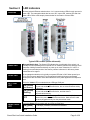
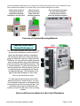
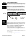
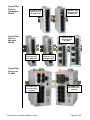
All these industrial Ethernet switches have 1 or 2 communication LEDs for each port and a
power LED. The managed models also have an “OK” output LED, a status LED and dual
power LEDs. Refer to the sample pictures below for the location of these LEDs.
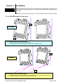
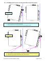
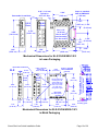
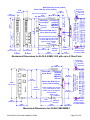
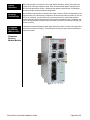
Typical LED Location (varies with model)
Status LED
Managed Models Only: The Status LED indicates the overall health of the switch. It is
normally ON solid indicating that no internal CPU or software problems are detected. It will
flash when loading firmware and briefly on power up or reset. Otherwise, if it is OFF or
flashing for an extended period of time then a problem is detected. In this case, please
contact Sixnet for support.
Power LED
On unmanaged models there is typically one power LED that is ON if either power input
(P1 or P2) has power applied to it. On the managed models (and some unmanaged
models) there are two Power LEDs that indicate if there is power applied to the respective
input.
ACT / LNK
LED
This is the Yellow LED on models with two LEDs per RJ45 port.
Indicates that there is a proper Ethernet connection (Link) between
ON (yellow) the port and another Ethernet device, but no communications activity
(not flashing)
is detected.
Indicates that there is a proper Ethernet connection (Link) between
ON (yellow) the
port and another Ethernet device, and that there is
(flashing)
communications activity.
OFF
Speed 10/100
LED
Indicates that there is not a proper Ethernet connection (Link)
between the port and another Ethernet device. Make sure the cable
has been plugged securely into the ports at both ends.
This is the Green LED on models with two LEDs per RJ45 port.
ON (green)
A 100 Mbps (100BaseT) connection is detected.
OFF
A 10 Mbps (10BaseT) connection is detected.
Sixnet Slim Line Switch Installation Guide
Page 6 of 30